CTB PigTek Rondomat 3S User manual

REVISED SEPTEMBER 2018 STU0001
F4420125

August 2018
© CTB, Inc. All Rights Reserved.
PigTek Limited Warranty & Disclaimer of Liability
LIMITED WARRANTY (“Warranty”)
PigTek Americas, a division of CTB, Inc. warrants new Products manufactured purchased from PigTek to be free from defects in
material or workmanship under normal usage and conditions, for One (1) year from the date of installation by the original purchaser
PigTek provides for an extension of the aforementioned Warranty period (“Extended Warranty Period”) with respect to certain Product
parts (“Component Part”) as set forth in the table below. If such a defect is determined by PigTek to exist within the warranty period,
the exclusive remedy will be to repair or replace the Product or Component Part at the sole discretion of PigTek, at no charge to the
Purchaser. Labor costs associated with the removal and/or installation of replacement and/or repaired Product or Component Part, as
well as freight costs, are not covered by this Limited Warranty. This Warranty is not transferable, and applies only to the Purchaser.
Component Part
Extended Warranty
Period
Fiberglass Housings
Lifetime
Cast Aluminum Blades
Lifetime
Rotating Centerless Augers (except where used in applications involving high moisture feed
stuffs exceeding 17%)
10 Years
Steel Auger Tubes
10 Years
Stainless Steel Feeders
5 Years
Hopper Bins
5 Years
Fan Plastic Shutter and Polyethylene Cones
3 Year
Motors and Bearings
2 Years
Chore-Time Control
2 Years
THIS WARRANTY CONSTITUTES CHORE-TIME’S ENTIRE AND SOLE WARRANTY AND PIGTEK EXPRESSLY
DISCLAIMS ANY AND ALL OTHER WARRANTIES, INCLUDING, BUT NOT LIMITED TO, EXPRESS AND IMPLIED
WARRANTIES, INCLUDING, WITHOUT LIMITATION, WARRANTIES AS TO MERCHANTABILITY OR FITNESS
FOR PARTICULAR PURPOSES. PigTek shall not be liable for any direct, indirect, incidental, consequential or special
damages which any Purchaser may suffer or claim to suffer as a result of any defect in the Product or Component Part.
Consequential or Special Damages as used herein include, but are not limited to, lost or damaged products or goods, costs of
transportation, lost sales, lost orders, lost income, increased overhead, labor and incidental costs, and operational inefficiencies.
Some jurisdictions prohibit limitations on implied warranties and/or the exclusion or limitation of such damages, so these limitations
and exclusions may not apply to you. This Limited Warranty gives the Purchaser specific legal rights. You may also have other rights
based upon your specific jurisdiction.
The following circumstances may render this Warranty void:
Modifications made to the Product or Component Part not specifically delineated in the Product or Component Part manual.
Product or Component Part not installed, tested, and/or operated in accordance with the instructions published by the PigTek.
All components of the Product are not original equipment supplied by PigTek.
Product was not purchased from a PigTek authorized distributor or certified representative.
Product was not installed by a PigTek authorized distributor or representative, or a licensed electrician.
Product or Component Part experienced malfunction or failure resulting from misuse, abuse, mismanagement, negligence,
alteration, accident, or lack of proper maintenance, or from lightning strikes, electrical power surges or interruption of electricity.
Product or Component Part experienced corrosion, material deterioration and/or equipment malfunction caused by or consistent
with the application of chemicals, minerals, sediments or other foreign elements.
Product or Component Part was used for any purpose other than for the care of poultry and livestock.
This Limited Warranty may only be modified in writing by an officer of PigTek. PigTek will have no obligation or responsibility for
any representations or warranties made by or on behalf of any distributor, dealer, agent or certified representative.
DISCLAIMER OF LIABILITY
Compliance with federal, state and local rules which apply to the location, installation and use of the Product are the responsibility of
the Purchaser. Chore-Time will not be liable for any damages which result from non-compliance with such rules.
PigTek Americas, A division of CTB, Inc.
PO Box 2000, Milford, Indiana 46542-2000 USA
www.choretime.com

i
1. General introduction.........................................................................................1
1.1 PigTek Sales & Service Center ..............................................................1
1.2 How to use this manual............................................................................1
1.3 Safety instructions....................................................................................2
1.4 Intended use.............................................................................................3
2. Introduction.......................................................................................................4
2.1 Parts of the Rondomat 3S........................................................................4
2.2 Parts of the control unit ............................................................................5
3. Place and mount the Rondomat 3S.................................................................6
4. Using the Rondomat 3S ...................................................................................7
4.1 Control options.........................................................................................7
4.2 Configure the Rondomat 3S.....................................................................8
4.3 Daily management ...................................................................................9
4.4 Maintenance...........................................................................................10
4.5 Cleaning.................................................................................................11
5. Technical specification ..................................................................................12
6. Appendix: connection diagram .....................................................................13

1
This manual has been compiled with the utmost care. If, however, you should
discover an error, please inform PigTek.
For any questions and support, please contact the local PigTek Sales & Service
Center.
The following symbols are used in this manual:
Tips and suggestions.
Note providing recommendations and additional information.
Warning indicating damage to the product if you do not follow procedures
carefully.
Warning indicating danger to humans or animals.
Electrical shock hazard. Danger to humans and animals.
Example of a practical application of the described functionality.
Calculation example.
Describes the key combinations for arriving at a particular screen.
Decimals
The control computer and this manual use a decimal point in values. For example: a
weight is shown as 1.5 kg (not as 1,5 kg).

2
Before installing and commissioning the Rondomat 3S, read the safety instructions,
provisions and conditions carefully. This paragraph contains a number of general
safety instructions. The installation of the device and remedying of any malfunctions
should be performed by a certified electrical installer according to the applicable
norms. The guarantee does not apply if this product is installed in any other way than
is indicated by PigTek and if the product's motor has been opened and changes
have been made to the product.
Never install a damaged Rondomat 3S! Notify your supplier of any damages.
Disconnect power before installation.
Take precautions against electrostatic discharge (ESD) when working on the
Rondomat 3S. Ensure the workplace is clean and dry.
Use correct wires as shown in the connection diagrams.
Make all wiring connections and check them before applying power. Incorrect
connections can cause permanent damage.
Never place the Rondomat 3S in a place where the weather has direct
influence (not in the sun, not in places where the temperature can rise sharply
etc.).
Inspect the Rondomat 3S periodically for any damages. Notify your
installation technician immediately of any damages. A damaged Rondomat
3S is unsafe!
Do not touch any of the Rondomat 3S moving parts.
The Rondomat 3S must only be assembled and installed by personnel with
the relevant technical qualifications who have read and understood these
manual. The safety instructions must always be observed.

3
The Rondomat 3S has been built in accordance with the latest technology and the
recognized technical safety rules. However, its use may lead to the risk of physical or
lethal injury to the user or third parties and/or damage to the machine and other
property.
The Rondomat 3S must only be used if it is in a technically perfect condition and in
line with its intended use, duly observing all safety risks and in accordance with the
Operating Instructions! Immediately remedy any malfunctions which may affect
safety! The Rondomat 3S:
has been developed specifically for the feeding of piglets.
must be installed and connected in keeping with the Assembly Instructions. Only
then is its safe operation possible and only then will the system work without any
problems.
must be operated in keeping with the ambient conditions laid down, i.e. in a
temperature range of 50o - 104o F (10o–40°C).
must be operated only with acid-free water.
Any use deviating from or exceeding this is considered to be improper. The
manufacturer is not liable for any damage resulting from such non-intended use.
Observing the Operating Instructions, specifically the safety instructions, and the
inspection and maintenance specifications is also an integral part of the intended
use.
4
The Rondomat 3S is designed to feed piglets automatically in places where piglets
are reared. Every Rondomat 3S can be operated locally from a permanently installed
control unit. The specific characteristics of the Rondomat 3S, which have resulted
from many years of development and construction experience, are:
Optimum reliability and optimum possibilities for monitoring and maintenance by
personnel.
Rapid and easy replacement of worn parts.
Amply spaced access openings, enabling easy, thorough and rapid cleaning.
Minimum space requirement due to compact design.
Long service life thanks to amply dimensioned construction elements and
bearings.
Optimum protection against corrosion.
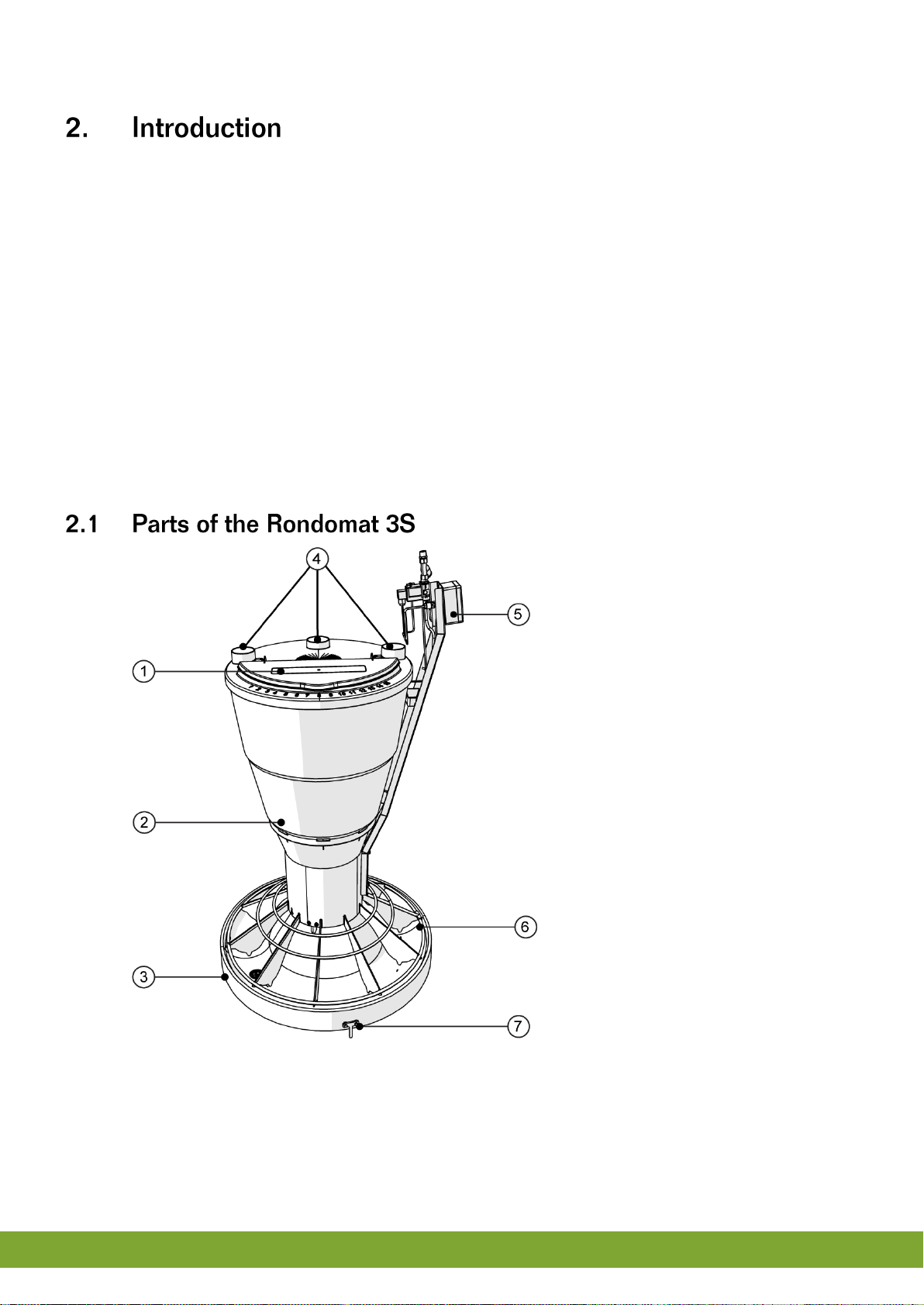
1. Feeding flap for manual feeding
2. Feed funnel
3. Round trough
4. Feeding intake via feeding lines
5
5. Control unit
6. Water ring
7. Legs
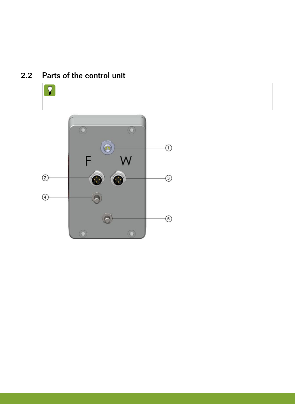
The connections for the dosing motor, the water valve and the moisture
sensor are located at the bottom. A fuse holder for primary and secondary
voltage is installed on the power supply unit.
1. Power supply connection
2. Dosing motor connection
3. Water valve connection
4. Trough sensor connection
5. Opposite pole trough sensor and fastening
6
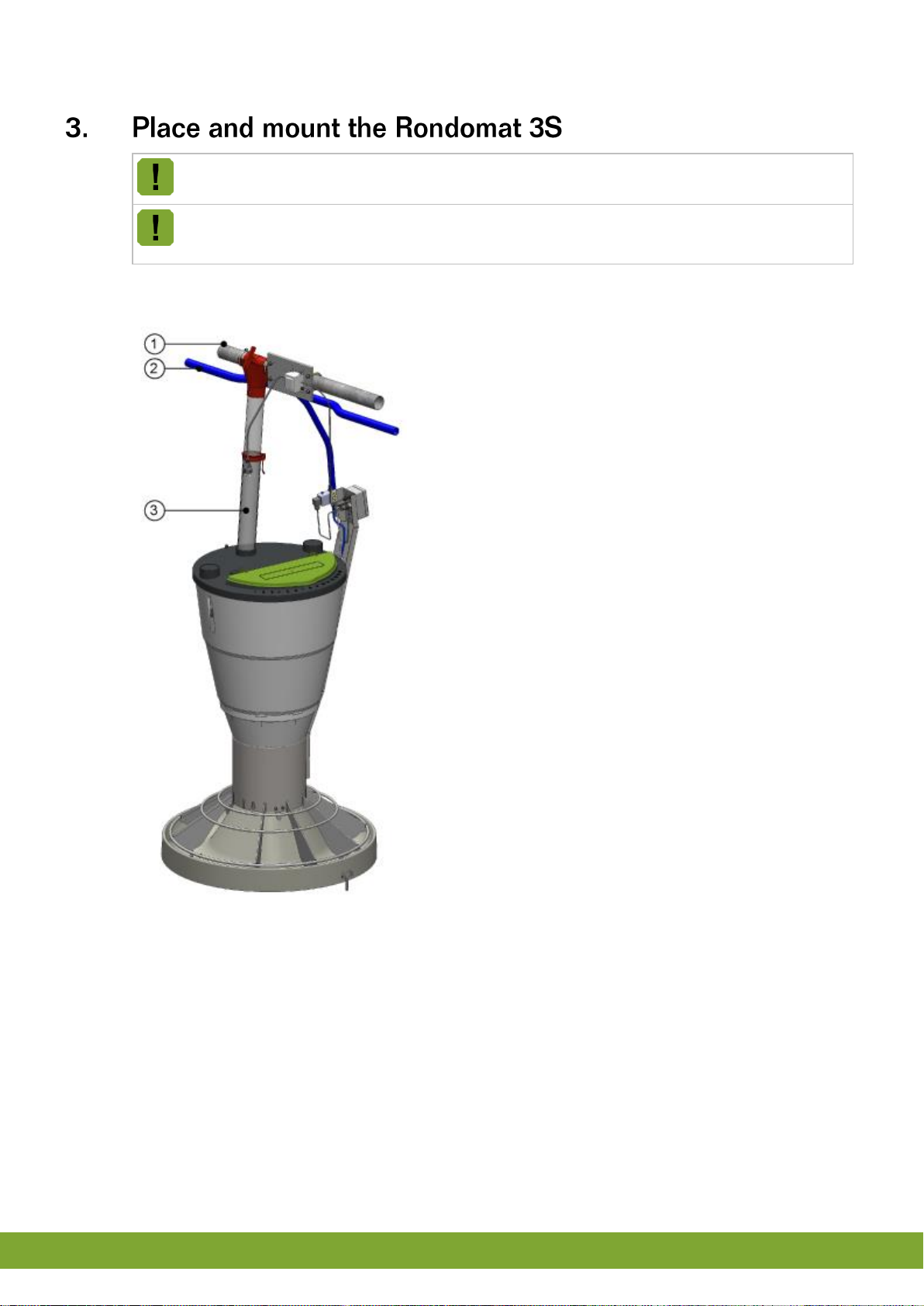
Place the Rondomat 3S with the mounted legs in the floor grid.
It is recommended to place the Rondomat 3S in the center of the house, so
the piglets have sufficient space around the Rondomat 3S.
Mount the feed and water lines
1. Feed line
2. Water line
3. Feed inlet

7
A control unit is installed at every Rondomat 3S. It consists of a water-
resistant, impact-proof front with input buttons, indicators and text displays.
1. Water setting display
2. Water plus button
3. Water minus button
4. Feed setting display
5. Feed plus button
6. Feed minus button
7. Trough sensor LED

8
You can configure the Rondomat 3S as follows:
1. Press and hold both the Water plus button and Water minus button.
The menu option is shown in the left display (Water setting display).
The relevant value is shown in the right display (Feed setting display).
2. Briefly press the Water plus button and Water minus button to toggle between the
individual menu options. The value shown can be changed by briefly pressing the
Feed plus button and Feed minus button.
3. Set the desired options:
Option 1: Set the pause time in seconds (value range: 1 to 99).
Option 2: Set the sensor sensitivity (value range: 1 to 99). Lower values
increase the sensor sensitivity whereas higher values decrease its sensitivity.
Option 3: Set the factory settings. Restore the default values (see below) by
pressing and holding the Feed plus button. A display test then follows in which
all displays repeatedly display the values 0 to 9 in ascending order. Press
Water plus button or Water minus button to end the test.
Option 4: Readout of the program version.
Option 5: Readout of the measured sensor value (only for service purposes).
Option 6: Readout of the measured sensor gradient (only for service
purposes).
If no button is pressed for a considerable time (approx. 30 sec.), the menu is
exited automatically
The default factory settings are:
Water: 0
Feed: 1
Pause time: 10 sec.
Sensor sensitivity: 10
9
The feed in the trough must always be sufficiently moist to enable the trough
sensor to work.
Initially, the feed presented should not be too liquid, but should be moist and
crumbly.
If the animals are fed by a wet/dry feeder after rearing, make sure that the
water content of the feed in the trough is increased slowly to accustom the
animals to liquid feed. This is not so critical when animals in a fattening house
are fed by a liquid feed dispenser.
Do not use acidic water! Acidic water can damage the standard water valve.
The feed, which can be in the form of pellets, granular feed or meal, is poured into
the feed funnel. During feeding, the crescent-shaped dispenser, operated by the
drive motor, releases feed. The feed is conveyed outwards, past the platform rim
over the entire surface and is equally distributed over the round trough. With every
revolution of the crescent-shaped dispenser, a preset amount of water is measured
out, controlled by a computer, onto the feed in the trough, via the water ring.
Dispensing stops as soon as the dosing time is finished.
Switch on/off the Rondomat 3S
To switch the Rondomat 3S on / off press and hold (for 3 sec.) both the Feed plus
button and Feed minus button. When the Rondomat 3S is switched off, the Trough
sensor LED lights up red. The status is also maintained in the event of a power
failure.
Set water amount
The amount of water measured out per dispensing action is shown in the Water
setting display. In principle, water is always dispensed for as long as feed is
dispensed, plus or minus the preset deviation in seconds (value range: -3 to 60).
Press the Water minus button to reduce the amount of water by up to three
seconds.
Press the Water plus button to increase the water dispensing time in steps of one
second.
Water pressure approx. 2 bar: set the water amount to 0.
Water pressure less than 1.5 bar: set a value in the range 1 to 3.
Water pressure more than 2.5 bar: set a value in the range -1 to -3.
Slowly increase the amount of water during the rearing process.

10
Set feed amount
The amount of feed measured out per dispensing action is shown in the Feed setting
display. The default setting is 1. Then the feed is dosed for five seconds (1 + 4 sec.)
(value range: 1 to 60).
Press the Feed minus button to reduce the feed dispensing time in steps of one
second.
Press the Feed plus button to increase the feed dispensing time in steps of one
second.
If the setting is 10, feed is dosed for 14 seconds (10 + 4 sec.).
The feed setting must be 1 at the start of the rearing phase.
Slowly increase the amount of feed during the rearing process.
Manual dispensing
Water can be dispensed manually by pressing and holding the Water plus button.
The water valve is opened for as long as the button is pressed and held.
Feed and water can be dispensed manually by pressing and holding the Feed plus
button. The water valve is opened and the dosing motor will run for as long as the
button is pressed and held.
Trough sensor
The Trough sensor LED lights amber when no feeding is detected and is off when
fed (motor works or will work soon).
No more feed will be dispensed for as long the trough sensor detects feed in
the trough.
This is a low-maintenance device. Its operation must be checked at regular
intervals.
We recommend keeping the device clean to guarantee optimum feed hygiene.
Clean it with water and diluted detergents (see Cleaning).
Depending on the water quality, the dirt trap on the water valve must be checked
and cleaned every now and then.

11
The device is very easy to clean thanks to its easy to understand construction
using only durable, corrosion-resistant materials such as plastic, stainless steel
and polymer concrete.
To clean the device, remove the feed funnel to make all sections accessible.
After cleaning, any water left behind in the trough can be drained by unscrewing
the cleaning stopper in the base of the trough.
Any moisture remaining on the platform must be removed using a cloth. Animals
can then be returned to the section.

12
Main power supply
Mains voltage:
115V / 230V / 75VA
Fuse:
Primary at 115V: 0.5A slow-acting
Primary at 230V: 0.25A slow-acting
Secondairy at 24V: 1.6A medium-acting
Water pressure:
1 - 3 bar
Housing
Trough diameter:
900 mm
Height:
1700 mm
Weight (unpackeged):
94 kg
Storing spare parts
The spare parts must be stored in a frost-free and dry location.
Rondomat
Feed storage containers:
70 liter
Feed places:
20
Feed places length:
2800 mm
Area which is occupied by the Rondomat:
0.63 m2

13
Connect the power supply
1. Power adaptor
2. 230V connector
3. 24 V power supply
Connect the ground cable
1. Ground cable

Note: The original, authoritative version of this manual is the English version produced by CTB, Inc. or any of its
subsidiaries or divisions, (hereafter collectively referred to as "CTB"). Subsequent changes to any manual made
by any third party have not been reviewed nor authenticated by CTB. Such changes may include, but are not
limited to, translation into languages other than English, and additions to or deletions from the original content.
CTB disclaims responsibility for any and all damages, injuries, warranty claims and/or any other claims
associated with such changes, inasmuch as such changes result in content that is different from the authoritative
CTB-published English version of the manual. For current product installation and operation information, please
contact the customer service and/or technical service departments of the appropriate CTB subsidiary or division.
Should you observe any questionable content in any manual, please notify CTB immediately in writing to: CTB
Legal Department, P.O. Box 2000, Milford, IN 46542-2000 USA.
Contact your nearby Chore-Time distributor or representative for additional parts and information.
Distributor Contact Information
Name: _____________________________________
Phone Number: _____________________________
Email: _____________________________________
PigTek, A Division of CTB Inc.
401 East Syracuse Street
P.O. Box 2000 • Milford, Indiana 46542-2000 • U.S.A.
Phone (574) 658-5000 • Fax (800) 236-6118
E-Mail: sales@pigtek.net • Internet: http//www.pigtekamericas.com
Printed in the U.S.A.
This manual suits for next models
1
Popular Farm Equipment manuals by other brands

New Holland
New Holland MegaCutter 512 Service manual

Malone
Malone ProCut 2000 Operator's manual

AgriProTech
AgriProTech ManTrac Option operating instructions

New Holland
New Holland FR480 Forage Cruiser Service manual

MacDon
MacDon R216 Quick Card

Highline Manufacturing
Highline Manufacturing FaStack 1200 Flex Operator's manual


