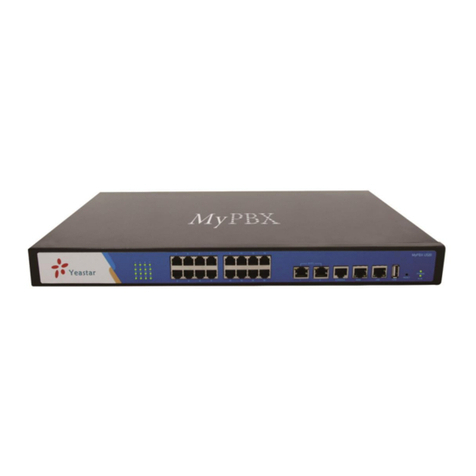
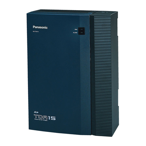
CTI TC-2000 AK Series User manual

TC-2000 AK
TC-2000 HK
TC-2000 DK
TC-2000 VK
PABX
Telephone Exchange
Series:
Instruction Manual
Instruction ManualInstruction Manual

TABLE OF CONTENTS
Section 1: Brief Introduction
Names -----------------------------------------------------------------------------------
Technical Index -------------------------------------------------------------------------
Part Name -------------------------------------------------------------------------------
System Connection Diagram ----------------------------------------------------------
Precautions ----------------------------------------------------------------------------- 12
Section 2: System Programming
General Programming Instructions ---------------------------------------------------
Default Values --------------------------------------------------------------------------
System Program Password -------------------------------------------------------------
Restore To Default Mode --------------------------------------------------------------
PABX Port Enable/Disable To Compatible With Key Phone ---------------------
Enable / Disable External Line ------------------------------------------------------
Attendant Mode Of CO Line ---------------------------------------------------------
Day And Night Service ----------------------------------------------------------------
External CO Line Ringing Extension At Operator Attendant Mode --------------
Attendant Extension At Auto-Attendant Mode -------------------------------------
Outgoing Message Record For Auto-Attendant Mode ----------------------------
Outgoing Message Play --------------------------------------------------------------
Holding Music Playing --------------------------------------------------------------
Extension(s) To Access Only One Appointed CO Line --------------------------
Exclusive CO Line Of Authorized Extension(s) ---------------------------------
Extension Group ---------------------------------------------------------------------
CO Line Group -----------------------------------------------------------------------
Restricted Prefix Digits -------------------------------------------------------------
Licence Prefix Digits ----------------------------------------------------------------
Extension Outgoing Class ----------------------------------------------------------
Extension Number Management ----------------------------------------------------
Extension Make External Call Mode -----------------------------------------------
Extension External Call Time Limited ----------------------------------------------
Extension Monitor Voice Record ----------------------------------------------------
Flash Time For Call Transfer --------------------------------------------------------
Extension Password Management --------------------------------------------------
Change System Time ------------------------------------------------------------------
Clear Call Bill(s) In Memory -------------------------------------------------------
Delay / Reverse Charge Mode -------------------------------------------------------
Third Outward Code -----------------------------------------------------------------
Priority Access & Monitor------------------------------------------------------------
2
8
9
11
14
14
15
15
17
18
20
21
22
23
23
24
25
26
27
29
29
30
32
34
35
36
37
38
39
39
40
40
41
13
13
TABLE OF CONTENTS
Section 3: Operation
Make Internal Call -------------------------------------------------------------------
Make External Call ------------------------------------------------------------------
Answer External Call ----------------------------------------------------------------
Call Pick Up ---------------------------------------------------------------------------
Transfer External Call To Another Extension -------------------------------------
Party Conference (2 Exts and 1 CO) ------------------------------------------------
Internal Call Transfer ----------------------------------------------------------------
Internal Party Conference ( among 3 extensions) ---------------------------------
Extension Call Operator --------------------------------------------------------------
Busy Transfer -------------------------------------------------------------------------
Unconditional Transfer --------------------------------------------------------------
Boss and Secretary Function ---------------------------------------------------------
Use Extension By Password ---------------------------------------------------------
Do Not Disturb ------------------------------------------------------------------------
Use Priority Access -------------------------------------------------------------------
Broadcasting ---------------------------------------------------------------------------
Verify Extension NumberAnd Port Number ---------------------------------------
Doorbell & Doorlock -----------------------------------------------------------------
Remote Program ----------------------------------------------------------------------
Section 4: Appendix
System Programming List ----------------------------------------------------------
Operation ------------------------------------------------------------------------------
PC Call Management Instruction --------------------------------------------------
PC Call Management Module Instruction ----------------------------------------
Section 5: Appendix
Key Telephone Brief Introduction -------------------------------------------------
42
44
45
45
46
47
47
48
49
49
50
50
52
52
53
55
57
59
54
59
62
56
56
60

Section 1: Brief Introduction
1
1. Any extension ports enable compatible with our Two-Wires Key Telephone
and limitless quantity, use it directly after connected.
2. Flexible Extension Number Assignment ( 2, 3 or 4 digits)
3. FSK / DTMF Caller ID, Internal and External Caller ID transferred
4. Extension Password
5. Different Class for Extension
6. Third Outward Code
7. Discretional Ringing Extension Assignment when Operator Attendant
Two Operator Extensions Assignment when Auto Attendant
8. 3 pieces OGM for auto-attendant use
9. Day and Night Service
10. Extension Call to Operator by one touch button
11. Busy Transferred, Unconditional Transferred and Do Not Disturb
12. Ten Difference Groups for Extensions and CO lines
13. Call Transfer, Three Parties Conference, Caller ID transferred
14. Support PC Call Management Software, have Reverse Detect function can
have nicety bill after apply Reverse Detect service from telecom office
15. Internal "Call Bill Memory" and Clock to ensure system can record the bill
even when PC Call Management software is not started
16. PC Voice Record Software optional
17. Remote Program function to make the maintenance easier.
TC-2000HK,DK and VK series have below additional features
1. Card Expandable. CO line, Extension increase / decrease freely
2. Power switch, DK&HK are internal batteries optional, VK is external batteries
optional, TC-2000DK series can keep working about 70 hours after power failure
3. External Music Input, allowed change the holding music freely
4. Allowed compatible with external amplifier for broadcasting
Welcome to use TC-2000 K series PABX, this series include these models:
TC-308AK ( 3 CO lines + 8 Extensions)
TC-416AK (4 CO lines + 16 Extensions)
TC-2000HK ( Card expandable structure, 2 to 6 CO lines, 4 to 32 Extensions)
TC-2000DK ( Card expandable structure, 4 to 16 CO lines, 8 to 128 Extensions)
TC-2000VK ( Card expandable structure, 8 to 16 CO lines, 32 to 64 Extensions)
The system is Card Expandable Structure, the main features are as below:

2
TC-2000AK 4
35
5
4
2
Left Side view
416AK Back View
308AK Back View
---- LED
---- Power Switch
---- CO line port
---- Extension port
----Power socket
---- COM port
---- Voice Record switch(OGM)
---- PC voice record port
Face View
1
3
Right Side View
678
1.1 Names
Section 1 Basic System Construction

PABX
TC-2000HK
2
1Front View
Telephone Exchange
3
Section 1 Basic System Construction
2
1
Side View
----LED
----Power Switch
----Power Socket
----Power fuse
----External Music Input Port
----COM Port
----Voice Recorder port
---- CO lines
---- Extensions
---- Expandable panel for rack mount (optional)
---- Back up battery box
--- 6v 4.5A/h Battery ( optional)
Back View
4
5
89
7
3
6
10
+-
Bottom View
11
12
11
12

Section 1 Basic System Construction
Front view
Back View
Internal View
1. Power supply LED
2. Power supply switch
3. CPU LED
4. CO line LED
5. Power supply socket
6.Fuse(2A)
7. CPU board
4
TC-2000DK
1
2
34
5
6
7 8 9 10
11 13
12
Telephone Exchange
8. Tone board
9. No.1 and No.2 CO line expansion board
10. Extension expansion board
11. Power supply board
12. Expansion board Location Solt
13. Internal battery (Optional)

Section 1 Basic System Construction
1
2
4
6
8
11
5
7
3
910
1.LED
2.C.O line port No.1 to No.8
3.C.O line port No.9 to No.16
4.Extension port No.1 to No.32 (default is corresponding with extension 8001 to 8032)
5.Extension port No.33 to No.48 (default is corresponding with extension 8033 to 8048)
6.Extension port No.49 to No.64 (default is corresponding with extension 8049 to 8064)
7.External Back Up Battery Connect Port
8.Lightning Protector Grounding
9.Power Socket, Power Switch
10.Cover Open Button
11.Computer COM Port, Voice Monitor Record Port, External Music Inputted Port
Lightning Protector grounding
Notes:
A1, A2are extensionA;
B1, B2 areextension B;
Connection Way:
Lightning Protector grounding
Notes:
A1, A2 are extension A;
B1, B2 are extension B;
Connection Way:
External
Music Input port
Broadcasting
Output port
PC Hard Disk
monitor record port
Voice Recorder port
PC COM Port
TC-2000VK
+ 48V
Battery
- 0
Front view
Internal view
Left Side view
5

1. LED
LED is light indicates corresponding C.O line or extension is using.
2. C.O line port No.1 to No.8
C.O line port No.1 to No.8 for connect with C.O line from telecom provider, each
RJ11 port for connect with two C.O lines, middle two lines (A&A) as one C.O line,
the two sides lines ( B&B) as another C.O line.
3.C.O line port No.9 to No.16
C.O line port No.9 to No.16 for connect with C.O line from telecom provider, each
RJ11 port for connect with two C.O lines, middle two lines (A&A) as one C.O line,
the side lines ( B&B) as another C.O line.
4.Extension port No.1 to No.32
Extension port of 8001 to 8032, each RJ11 port for connect with two extensions,
middle two lines (A&A) as one extension, the side lines ( B&B) as another extension.
Auto-compatible with both of keyphone and normal telephone, the maximum transmit
distance between extension and PABX can be up to 1000 meters when lines at well
connecting.
5.Extension port No.33 to No.48
Extension port of 8033 to 8048, each RJ11 port for connect with two extensions,
middle two lines (A&A) as one extension, the side lines ( B&B) as another extension.
Auto-compatiblewith both of keyphone and normal telephone, the maximum transmit
distance between extension and PABX can be up to 1000 meters when lines at well
connecting.
6.Extension port No.49 to No.64
Extension port of 8049 to 8064, each RJ11 port for connect with two
extensions, middle two lines (A&A) as one extension, the side lines ( B&B) as
another extension. Auto-compatible with both of keyphone and normal telephone,
the maximum transmit distance between extension and PABX can be up to 1000
meters when lines at well connecting.
7.External Back Up Battery Connect Port
Power switch design allows connect 48V external back up battery that ensure system
can keep working normal for certain period of time when power failure, the working
duration is depends on calls frequency, normally could remain about 48 hours when
full charge.
Section 1 Basic System Construction
6

8.Lightning ProtectorGrounding
In order to prevent system is damaged by lightning, we are strongly suggest user
make grounding for system by connect this point.
9.Power Socket:AC-200V power socket (allows make to AC-100V according
customer's need), we are suggest to turn offpower when shift or install PABX in
order to ensure safe;
Power Switch:Use for turn ON or OFF power supply of PABX, we are suggest to
turn off power when installing or connecting in order to prevent system is damaged.
10.Cover OpenButton
Press these two bottons at the same time to open cover.
11.Computer COM Port: For connect with computer COM port in order can use our
CTI ( Computer Telephony Integration ) software. The ideal cable length between
PC and PABX is less 100 meters.
Voice Monitor Record Port: For connect with computer sound card in order can
record phone conversation to computer.
External Music Inputted Port: Allows user input favorite external music source
from CD, radio, etc as holding music in order can auto replace pre-set inner music,
but external music source is required keep playing.
Section 1 Basic System Construction
7

Capacity (Different model has different capacity)
Outside (CO) Lines =2,3, 4, 6, 8, 12 or 16
Extensions = 4 to 128
Exterior sockets: Extension/CO line, PC network,
TC-2000DK & VK series have additional features:
Tone Output, External Music Input, Voice Recorder, Broadcast.
Communication Channels: AK = 7 HK = 7 DK=15 VK=15
Transmission Attributes:
Extension to Extension 1.5dB
Extension to Trunk line 2.0dB
Ringing Current:
Model AK = AC 65V/50Hz
Model HK, DK, VK = AC65V/25Hz
Feeding Current = DC 48V/25mA
Relative Unbalance Against Ground:
300Hz-600Hz 40dB
600Hz-3400Hz 46dB
Dialing Mode: DTMF
1.2 Technical Index
Section 1 Basic System Construction
8
Signal Tone:
CO Line: Tone from Local Telecom Office
Internal Dial Tone: 450Hz, Continuous Square Wave
Internal Ringing Tone: 450Hz, square wave, 1sec on and 4sec off
Internal Busy Tone: 450Hz, square wave, 0.3sec on, 0.3sec off
Internal Verify Tone: 450Hz, square wave, 1sec on
Internal Error Tone: 450Hz, square wave, 0.3sec on, 0.3sec off
Caller ID:
Receive: DTMF, FSK Bell 202)
Send: DTMF
Power Supply:
AK: AC220V 10% /15VA HK: AC80V 260V /35VA
DK: AC80V 260V /60VA VK: AC80V 260V /50VA
Backup Battery
HK: 6V/10AH*1pcs Charge current 1A
DK: 12V/7AH*4pcs Charge current 200mA
VK: 12V/7AH*4pcs Charge current 200mA
HK,DK,VK: External Music Input Power Level: 1Vrms Resistance:10K
HK,DK,VK: Broadcast Output Power Level: 200mVrms Resistance:1K
DK,VK Telephone Voice Recorder Control Voltage:48V/10V
In Point Environment:
Temperature: 0 C-40 C
Relative humidity 90%

1.3 Part Name CPU is the control center of PABX,have control chip,connection circuit.
One socket in the CPU board is for PC COM port connecting, supplied
one switch is allowed connect with PC COM port
The user can make the connecting cable by ordinary 4pin telephone
cable as follows ( Advert the color order of cable and orientation of
the Rj11 plug and the telephone cable is within 100 meters)
1
1 CPU board
Facture 1 Uncover the two ports(port A and port B)of 4 pins
telephone cable with appropriate length;
2 Unkit the cable, the color order is Yellow, Red, Green
and White;
3 Use two standard Rj11 plugs, insert the telephone cable
by the same color orientation into the same orientation
Rj11 port (port A and port B);
4 Make sure the telephone cable has been inserted well,
impact it by plier;
Tone board is take on generates internal dial tone, ringing tone,
false tone, music, and compile the extension dialing, have many
molectron, be avoid the static when insert or remove the card.
Part Names
1 Volume Switch for Music on Holding
2 External Music Input pot. Can adopt ordinary mono plug,
input radio, CD or Mp3 as external music source for
call on holding
3 OGM protection switch to avoid the internal OGM
does not swilled out by the interference(Refer 2.26 page18)
4 Broadcasting port (Refer 3.19 page 45)
5 Voice Recorder port (Refer 2.63 page 32)
6 PC Record port (Refer 2.63 page 32)
1
2
3
4
5
6
2 Tone board
switch
Rj11 plugA
White
Green
Red
Yellow
Port B
Plug Flatly
White
Green
Red
Yellow
Port A
Switch
9
Section 1 Basic System Construction

Outside (CO) line board is take on connect with PSTN,
various CO line signal can transmit to each extension
port by tone exchange system that in CO line board to
realize communicating between CO line and Extension.
Allowed maximum install two pieces of CO line board,
and have 8 CO line ports in each CO line card, maximum
have 16 CO lines.
The port order of No.1 CO line board are 01~08 from the
bottom up; the No.2 CO line board are 09~16 from the
bottom up.
The line will priority enter the idle lower CO line port
when internal extension make the external call.
To reduce the CO lines are occupied by the outgoing
calls, we suggest to connect the high-frequency used
CO lines that for external call incoming to the higher
CO line port
Arrester is a device to be installed on outside (CO) line
to prevent a damaging from thunder. We recommend
to install arrester. In addition, grounding (connection to
earth ground) is very important to protect the system.
(Thunder damaging is void warranty)
Extension board is connecting with internal telephone,
the system can build internal communication or external
call by tone exchange system.
Maximum allowed connect with sixteen extension cards,
have 8 extension ports in each board, total have 128
extensions. The port order of each extension board is
increased from the bottom up, The No.1 card are 01~08,
the No.2 board are 09~16 from the bottom up, thus
analogically.
We are recommend to installed the arrester for extension
lines when the extension lines are expose at outdoor.
3 CO line board
4 Extension board
No.1
CO line board
01
02
03
04
05
06
07
08
09
10
11
12
13
14
15
16
No.2
CO line board
01
02
03
04
05
06
07
08
09
10
11
12
13
14
15
16
No.2
Extension board
No.1
Extension board
10
Section 1 Basic System Construction

11
Section 1 Basic System Construction
1.4 System Connection Diagram
Amplifier
Voice Recorder
Computer
COM Port
Junction Shelf
Arrester
CO line Extension
AC 80v 260v
MP3
External
Music
With creepage protection
Arrester
Junction Shelf
Ground Wire
VOIP
Internet

1. The connection way of model AK,HK,VK are almost as same as DK, please refer above
chart when connecting.
2.
4.
5.
6.
7.
A lightning protector is a device to be installed on an outside (CO)line to prevent
a dangerous surge from entering the building and damaging the equipment, please
use less 10ohm resistor grounding arrester for CO line.
3.System must be at well grounding condition, otherwise system may operates
un-properly.
Avoid install telephone cable at outdoor, do not wire telephone cable in parallel
with power source, computer, telex, etc. Otherwise, the system operation may be
interfered by the electromagnetism from such equipment.
Install at least 50cm away from flammability or volatile, avoid install on dusty
places, or places where water or oil may come into contact with system.
Unplug the system when change card, draw or insert card vertically.
Adopt power switching, input voltage is 80V~260V, power switching only
control DC power, don't control AC power.
8.The system can be equipped with an external music source to replace internal
built-in music, input signal voltage range is 0.5V~2V. Voice Recorder port is
exclusive for connect with monitor voice recorder(model LH-2000).
9.System serial communication port is for connect with PC COM port, allows
realize multi-functions application and PC charge function when work with our
CTI (computer and telephone integrated ) software.
10.Please read manual carefully before connecting and programming, avoid error
program cause system doesn't operates properly, please reset power supply
when a failure occurs, or contact with your dealer. This unit may only be
installed and served by qualified service personnel.
1.5 Precautions
12

Section 2 System Programming
2.1.1 This system has a default factory setting. If any of the programming needs to be
changed, the user can change the setting by system programming.
2.1.2
2.1.3 The user should input the password to enter the system programming.
2.1.4
2.1.5
2.1.6
2.1.7
2.1.8 In this manual, we have marked when the functions are different for different
model AK,HK,DK,VK.
All programming must be operated on extension 1 (default is 8001) or by computer
when use our CTI software. When extension is at direct outgoing mode, please input
'' * '' to enter internal dial mode first, then go ahead.
Input '' * '' to start program and end with '' #'', allows input '' * '' to restart program
in the event of failure program occurs.
A long BEEP tone indicates correct programming, if instead of three serial BEEP
tone indicates error programming.
If without special remark, here in manual extension number ''ABCD'' indicates
extension current number, not default extension number.
Any extension is capable connect with our key telephone, plug and play when change
single line telephone to key telephone; however, when change key telephone to single
line telephone, you are required to input format ###0 on key telephone first,
otherwise, system may doesn't operates properly.
2.2 Default Values
* Attendant mode: Operator Attendant
* Ringing extension at operator attendant: 8001,8002,8003,8004
* Operator No.1Extension at auto-attendant: 8002
Operator No.2 Extension at auto-attendant: 8003
* External Dial Mode: Dial 0 or Select CO line
* CO line Caller ID mode: Standard FSK, DTMF
* Trunk Group: Not set
* Extension / CO line group: 0
* Extension outgoing class: No restriction
* Restricted/ Licence Prefix Digits: Not set
* Extension / CO lines Monitor Record mode: Not set
* Extension External Call Time Limited: Not set
* Hook-Switch Flash time:760 ms
13
2.1 General Programming Instructions

2.4 Change System Program Password
Format: * 02 ABCD #
ABCD = New password (Default password = 1234)
Example, you want to change the password to 0000 :
Example:
The default password is 1234. We suggest to change the password before using
the PABX. If the user wants to change the password to 5678, the user should input
* *01 1 2 3 4 # to enter the system, then input * 02 5 6 7 8 # to change the password
to 5 6 7 8.
Suppose the user needs to change the password again to 1111, the user should input
** 01 5 6 7 8 # to enter the system, then input * 02 1111 # to change the password
to 1111.
When you forget program password, please contact with your dealer to
restore the password by Remote Program function.
*2
14
03#
Pick up 8001 Input ** 01 1234 # Du programming
1
Pick up 8001(unlock) Input * 0 2 0 0 0 0 # Du Hang up
0
*20000#
2.3 System Program Password Entry
Format: * * 01 ABCD #
ABCD = System Program Password.
Description: Allows the user to enter system programming by system program
password,suppose the password is 1234 .
If the user has entered into the programming mode by password, the user
should not hang up extension 8001 until all the desired system settings
have been modified, otherwise the user has to input the password again to
enter into the programming mode.
14
Section 2 System Programming
*
Format: * 6 000 #
Description:This format to restore the system to avoid useless data left after testing.
Note: This format is not restore the CO line Open mode, Extension Number and
Call Bill Memory.
2.5 Restore To Default Mode

Format: * 84 ABCD M #
ABCD = Extension Number
M=0= Use Single Line Telephone
M=1= Use Key Telephone
Description: Initially enable connect key phone or single line phone with any
extension port of PABX, auto-configure after power ON, dispense
with assignment.
Certain extension port change from Key phone to Single Line phone, require input
* 84 ABCD 0# on Key Phone that connect with 001 port. (001 is un-lock).
Example: PABX Extension port 8008 has used Key Telephone, now, change it to
use Single Line Telephone.
3*4
11#
2
8*0
848
0
Pick up 8001(unlock) Input * 84 8008 0 # Du Hang up
#0##
Format: * 84 #
All extension ports are disable compatible with Key Phone.
2.6 Extension Port Enable/Disable To Compatible With Key Phone
Key Phone
2.7 Disable Compatible Key Phone For All Extension Ports
15
Section 2 System Programming
Format: * 3 1 ABCDEFGH #
ABCDEFGH = CO Line ports number = No.1CO line card of DK model = 1 to 8
Description: Assigns which external ( CO ) line is connected to which CO line port.
Example : The port 1, 2,3,4,5 of No.1 CO line card is connected with CO lines, it
is correspond to CO line 1, 2, 3, 4, 5.
2.8 Enable External (CO) Line ( No.1 Co Line Card )
3*4
11#
2
3*3
114
2
Pick up 8001(unlock) Input * 31 1 2 3 4 5 # Du Hang up
#5##
2.9 Disable No.1 CO Line Card
Format * 31 #
Description: When the No.1 CO line card is not installed or it has not CO line,
please close/disable it to avoid no response when pick up extension.

Format: * 3 2 ABCDEFGH #
ABCDEFGH = CO Line ports of No.2 card = 1 to 8
Description: Assigns which external ( CO ) line is connected to which CO line port.
Example :The port 1, 2,3,4,5 of No.2 CO line card is connected with CO lines, it is
correspond to CO line 9, 10, 11, 12, 13.
3*4
11#
2
3*3
124
2
Pick up 8001(unlock) Input * 32 1 2 3 4 5 # Du Hang up
2.10 Enable External (CO ) Line ( No.2 CO Line Card )
#5##
16
Section 2 System Programming
1. This format is only function for model DK,VK.
2. The port number 1 to 8 of No.2 CO line card are correspond to actual CO
line 9 to 16.
3. The line will priority enter the idle lower CO line port when internal
extension make external call. Example,CO line 1,2,3,4,5 have been
connected, the extensionA will access CO line 1, meanwhile, extension B
will access CO line 2.
To reduce the CO lines are occupied by the outgoing calls , we suggest to
connect the high-frequency used CO lines that for external call incoming
to the higher CO line port
4. The CO line can be connected do not accord to the order, for example, we
can connect CO line 1,2,5,6,7,8, leave the port 3 and 4 are vacant.
2.11 Disable No.2 CO Line Card
Format * 32 #
Description: When the No.2 CO line card is not installed or it has not CO line,
please close/disable it to avoid no response when pick up extension.
2.12 Disable All CO Lines
Format * 3 #
Description When no CO line card is installed or CO line card has not CO line,
please close all CO lines to make PABX is at Intercom mode.
Example: Assign PABX at Intercom mode when no CO lines are connected.
3*3*
Pick up 8001(unlock) Input * 3 # Du Hang up
##

Format: * 2 1 #
Description: Assigned ringing extension will ring when CO line is received, pick
up extension to answer the call.
2.13 All CO Lines At Operator Attendant Mode
*12#
Pick up 8001(unlock) Input * 2 1 # Du Hang up
17
Section 2 System Programming
Format: * 20 #
Description: In this mode, the external caller will hear the Out Going Message recording.
None of the extension will ring.
*02#
Pick up 8001(unlock) Input * 2 0 # Du Hang up
2.14 All CO lines At Auto-Attendant (Outgoing Message)
Format: * 2 1 mn #
mn = CO line port number(01-16)
Description: Assign operator-attendant mode for certain CO lines, while other CO
lines remain in auto-attendant mode.
Example: Assign CO 3 at operator-attendan, and assign remain CO lines at auto
attendant mode.
Suggest to assign all CO lines at auto-attendant mode before this assignment
to avoid conflicts with previous setting.
*0#
2*#0
123
Pick up 8001(unlock) Input * 2 0 # Du Input * 2 1 03 # Hang up
2.15 Certain CO line(s) At Operator Attendant Mode
This manual suits for next models
7
Table of contents
Popular PBX manuals by other brands

Nortel
Nortel Meridian 1 PC Console Interface Unit Scripting Guide

Panasonic
Panasonic KX-TD816 Features guide

Panasonic
Panasonic KX-NCP500 Quick reference guide

Panasonic
Panasonic KX-TDA30 user manual

Panasonic
Panasonic KX-TDA50G Brochure & specs

Fortinet
Fortinet FortiVoice Enterprise 3000E quick start guide