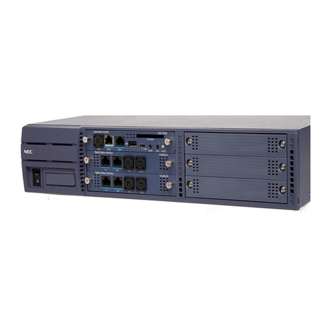
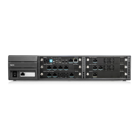
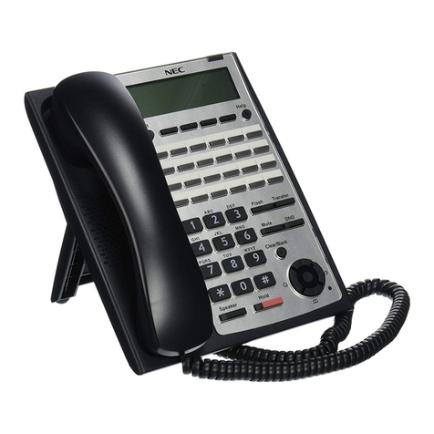
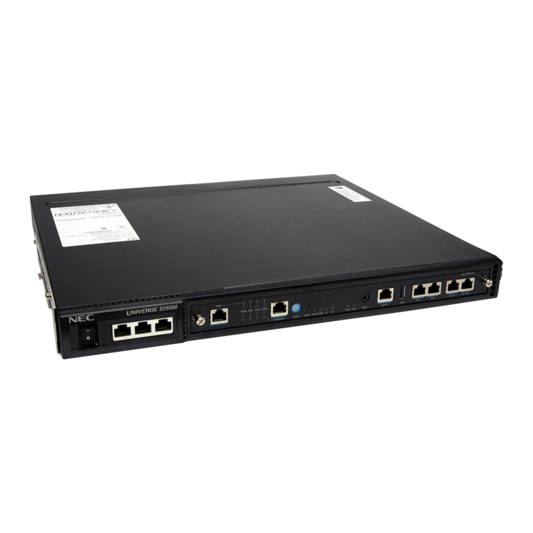
NEC SV8300 User manual

System Maintenance Manual
NWA-033627-001
ISSUE 4.0

LIABILITY DISCLAIMER
NEC Corporation reserves the right to change the specifications,
functions, or features, at any time, without notice.
NEC Corporation has prepared this document for use by its employ-
ees and customers. The information contained herein is the property
of NEC Corporation and shall not be reproduced without prior written
approval from NEC Corporation.
Dterm is a registered trademark of NEC Corporation.
PCPro is a trademark of NEC Corporation.
Copyright 2010
NEC Corporation

i NWA-033627-001 Rev.4.0
95toc001.fm
TABLE OF CONTENTS
INTRODUCTION
PURPOSE ................................................................................................................ 1
OUTLINE OF THIS MANUAL ................................................................................... 2
TERMS IN THIS MANUAL ....................................................................................... 3
PBX System Designation ................................................................................................. 3
Terminal Name ................................................................................................................ 3
REFERENCE MANUAL ........................................................................................... 5
PRECAUTIONS ........................................................................................................ 6
System Data Backup ....................................................................................................... 6
Chapter 1 MAINTENANCE SERVICES
HOW TO READ THIS CHAPTER ............................................................................ 1-2
FAULT MESSAGE ................................................................................................... 1-3
General Description ......................................................................................................... 1-3
Fault Message ............................................................................................................. 1-3
External Alarm Display Panel ...................................................................................... 1-4
Service Conditions ........................................................................................................... 1-5
Fault Message ............................................................................................................. 1-5
External Alarm Display Panel ...................................................................................... 1-5
Programming Procedure .................................................................................................. 1-6
Fault Message ............................................................................................................. 1-6
External Alarm Display Panel ...................................................................................... 1-15
Operating Procedure ....................................................................................................... 1-15
STATION LINE STATUS DISPLAY .......................................................................... 1-16
General Description ......................................................................................................... 1-16
Service Conditions ........................................................................................................... 1-16
Programming Procedure .................................................................................................. 1-16
Operating Procedure ....................................................................................................... 1-16
BATTERY RELEASE CONTROL ............................................................................. 1-18
General Description ......................................................................................................... 1-18
Service Conditions ........................................................................................................... 1-18
Programming Procedure .................................................................................................. 1-18
Operating Procedure ....................................................................................................... 1-19
DIAGNOSTICS ......................................................................................................... 1-20
General Description ......................................................................................................... 1-20
Service Conditions ........................................................................................................... 1-20
Programming Procedure .................................................................................................. 1-21
Operating Procedure ....................................................................................................... 1-21
JULY/17/2009

ii NWA-033627-001 Rev.4.0
95toc001.fm
BATTERY REPLACEMENT ..................................................................................... 1-28
FAULT REPORT SCHEDULING .............................................................................. 1-29
General Description ......................................................................................................... 1-29
Service Conditions ........................................................................................................... 1-29
Programming Procedure .................................................................................................. 1-30
Operating Procedure ....................................................................................................... 1-31
VoIP LOG COLLECTION ......................................................................................... 1-32
General Description ......................................................................................................... 1-32
Service Conditions ........................................................................................................... 1-34
Programming Procedure .................................................................................................. 1-42
QoS DISPLAY ON IP MULTILINE TERMINAL ........................................................ 1-46
General Description ......................................................................................................... 1-46
Service Conditions ........................................................................................................... 1-47
Programming Procedure .................................................................................................. 1-47
STATION SERVICE STATUS DISPLAY .................................................................. 1-48
General Description ......................................................................................................... 1-48
Service Conditions ........................................................................................................... 1-48
Programming Procedure .................................................................................................. 1-49
PING COMMAND ..................................................................................................... 1-52
General Description ......................................................................................................... 1-52
Service Conditions ........................................................................................................... 1-52
Programming Procedure .................................................................................................. 1-55
Operating Procedure ....................................................................................................... 1-56
Chapter 2 TROUBLESHOOTING
PRECAUTIONS ........................................................................................................ 2-2
Grounding Requirements ................................................................................................. 2-2
Static Electricity Guard .................................................................................................... 2-3
Turning Power ON ........................................................................................................... 2-6
Turning Power OFF ......................................................................................................... 2-6
OUTLINE OF TROUBLESHOOTING ....................................................................... 2-7
FAULT DETECTION ................................................................................................ 2-8
LED Indication on Blades ................................................................................................ 2-9
FAULT INFORMATION DISPLAY ............................................................................ 2-12
Display on PCPro/CAT .................................................................................................... 2-12
Fault Message ............................................................................................................. 2-12
Fault Diagnosis and Troubleshooting .............................................................................. 2-16
Station Line Status Display ......................................................................................... 2-30
Troubleshooting by LED Indication on Blades ................................................................. 2-33
Troubleshooting by Contents of Complaint ...................................................................... 2-37
Explanation of Symbols in Troubleshooting Procedure .............................................. 2-38
How to Follow the “Tree” ............................................................................................. 2-38
JULY/17/2009
iii NWA-033627-001 Rev.4.0
95toc001.fm
Station Line Fault ........................................................................................................ 2-40
C.O. Line/Tie Line Fault .............................................................................................. 2-42
Power Failure Transfer (PFT) Fault ............................................................................ 2-51
Digital Multiline Terminal Fault .................................................................................... 2-52
IP Station Fault ............................................................................................................ 2-54
DESKCON Fault ......................................................................................................... 2-56
DSS Console Fault ...................................................................................................... 2-57
JULY/17/2009

iv NWA-033627-001 Rev.4.0
95toc001.fm
THIS PAGE LEFT BLANK INTENTIONALLY.
JULY/17/2009
INTRODUCTION
1NWA-033627-001 Rev.4.0
95ch0001.fm
PURPOSE
INTRODUCTION
PURPOSE
This manual explains the maintenance services provided with the SV8300, and the recommended trouble-
shooting procedure when a fault has occurred, for maintenance personnel of this system.

INTRODUCTION
2NWA-033627-001 Rev.4.0
95ch0001.fm
OUTLINE OF THIS MANUAL
This manual consists of two chapters. The following paragraphs summarize Chapters 1 and 2.
CHAPTER 1 MAINTENANCE SERVICES
This chapter describes the general description, service conditions, programming and
operating procedure of the maintenance services.
CHAPTER 2 TROUBLESHOOTING
This chapter describes the precautions before troubleshooting, and the troubleshoot-
ing procedure flow chart.
NOTE: For the following features, refer to the PC Programming Manual.
• CPU Program Upgrade
• System Data Save/Load/Verify
NOVEMBER/21/2008

INTRODUCTION
3NWA-033627-001 Rev.4.0
95ch0001.fm
TERMS IN THIS MANUAL
PBX System Designation
PBX system is designated as “PBX” or “system” usually.
When we must draw a clear line between the PBX systems, they are designated as follows.
SV8300: UNIVERGE SV8300
Terminal Name
The following terminals are designated as “Multiline Terminal” usually, unless we need to mention the
type of terminal in particular.
TERMINAL NAME PRODUCT NAME
Multiline
Terminal
Digital Multiline Terminal Dterm Dterm70 (Elite)
Dterm75 (Series E)
Dterm85 (Series i)
DT300 Series DT310
DT330
IP
Station
IP Multiline Terminal IP Enabled Digital
Multiline Terminal
[North America
only]
Dterm75 (Series E)
(IP Adapter Type)
Dterm85 (Series i)
(IP Adapter Type)
DtermIP INASET
DtermIP Dterm85 (Series i)
(IP Bundled Type)
Soft Phone DtermSP30
SP350
SIP Multiline Terminal DT700 Series DT710
DT730
DT750
Continued on Next Page
APRIL/16/2010

INTRODUCTION
4NWA-033627-001 Rev.4.0
95ch0001.fm
TERMS IN THIS MANUAL
NOTE: Dterm75 (Series E)/Dterm85 (Series i) terminal can be used as the IP terminal by attaching the
IP Adapter (IP Enabled Digital Multiline Terminal). This terminal provides users with all fea-
tures currently available in IP Station.
TERMINAL NAME PRODUCT NAME
Multiline
Terminal
IP
Station
SIP
Station
SIP Wireless
Terminal
MH240
IP Single Line
Telephone
(SIP)
IP Single Line Telephone (SIP)
APRIL/16/2010

INTRODUCTION
5NWA-033627-001 Rev.4.0
95ch0001.fm
REFERENCE MANUAL
REFERENCE MANUAL
Refer to the following manuals during maintenance and troubleshooting:
Command Manual:
Contains the Customer Administration Terminal (CAT) operation, command functions and data re-
quired for programming the system.
PC Programming Manual:
Contains the functional description and the installation procedure for the PCPro.
System Hardware Manual:
Contains the installation procedure for the PBX system and the hardware installation procedure for
the SV8300.

INTRODUCTION
6NWA-033627-001 Rev.4.0
95ch0001.fm
PRECAUTIONS
PRECAUTIONS
System Data Backup
CAUTION
• If you operate as follows without system data backup after system data setting or service
memory setting (registration of the features such as “Call Forwarding” and “Speed Calling
[Speed Dialing]” from a station), the data that has been set is invalid.
You must execute the system data backup before the following operations.
-Turning Off the system
-System Reset (reset of CPU blade)
-Changing the CPU blade to Off-Line Mode
-Changing the CPU blade to On-Line Mode after system data setting under Off-Line Mode
• You can execute the system data backup by the following two ways.
-Executing the system data backup once a day at the time set by CM43 Y=5>00
(If no data is set, the default setting is 3:00 a.m.)
-Executing the system data backup from PCPro/CAT by CMEC Y=6>0: 0
• Do not reset the CPU blade while “SYSD” LED on the CPU blade is flashing.

1-1 NWA-033627-001 Rev.4.0
95ch1001.fm
Chapter
1
UNIVERGE SV8300
System Maintenance Manual
MAINTENANCE SERVICES
This chapter describes the general description, service conditions,
programming and operating procedure of the maintenance services.

Chapter 1 MAINTENANCE SERVICES
1-2 NWA-033627-001 Rev.4.0
95ch1001.fm
HOW TO READ THIS CHAPTER
In the programming procedure, the meaning of (1), (2) and marking are as follows:
(1): 1st Data
(2): 2nd Data
: Default
With the system data clear command (CM00, CM01), the data with this marking is automatically
assigned for each command.
: Command with this marking can be used only under Off-Line mode of the CPU
blade.
To set Off-Line mode,
(1) Set SENSE switch on the CPU blade to “E” or “F”.
(2) Press RESET switch on the CPU blade.
OFF LINE

Chapter 1 MAINTENANCE SERVICES
1-3 NWA-033627-001 Rev.4.0
95ch1001.fm
FAULT MESSAGE
FAULT MESSAGE
General Description
Fault Message
This feature stores fault information into the Fault Store Memory, and displays the fault information on the
PCPro or the Customer Administration Terminal (CAT). For CAT operation, refer to the Command Man-
ual.
The display format using PCPro is shown below:
The fault information is displayed in the order that faults occur.
Continued on next page
No. Item Description
(1) Access Date field Displays the date and time at which the fault informa-
tion was last read.
(1)
(2)
(3)
APRIL/16/2010

Chapter 1 MAINTENANCE SERVICES
1-4 NWA-033627-001 Rev.4.0
95ch1001.fm
FAULT MESSAGE
External Alarm Display Panel
[8300R3 software required]
When a fault has occurred in the system, you can detect the fault by a Major (MJ) alarm or Minor (MN)
alarm indicated on external equipment (Alarm Display Panel).
No. Item Description
(2) Fault Display
Area
Number field Displays the unique number assigned to the fault infor-
mation.
Occurrence Date
and Time field
Displays the date and time at which the fault occurred.
Error Type field Displays the number of the fault type.
Alarm field Displays the alarm type of the fault.
-- : No alarm
MN : MN alarm
MJ : MJ alarm
Unit/Slot/Circuit
field
Displays relevant information only if the fault infor-
mation pertains to a unit, slot or circuit; otherwise, dis-
plays “-”.
(3) Data field Displays detailed information about the fault selected
in the Fault Display area.
SV8300
(MJ/MN Alarm)
Alarm Display Panel
Fault Information
JULY/17/2009

Chapter 1 MAINTENANCE SERVICES
1-5 NWA-033627-001 Rev.4.0
95ch1001.fm
FAULT MESSAGE
Service Conditions
Fault Message
(1) The maximum number of fault information that can be stored is 10.
(2) The alarm kind (Major Alarm, Minor Alarm or No Alarm Indication) can be programmed by CMEA
Y=2 or set by PCPro for each fault kind.
External Alarm Display Panel
[8300R3 software required]
(1) “MJ Alarm occurred” or “MN Alarm occurred” displays on the external equipment.
(2) The notification for maintenance is indicated by the alarm lamp (MJ/MN) on external alarm panel.
The MJ or MN alarm is assigned by CMEA Y=2.
(3) External Alarm Indication of external equipment cannot be cleared by CMEA Y=0>F from PCPro/
CAT.
(4) External Alarm Indication of external equipment can be cleared by CMEA Y=1>00/01/02 from
PCPro/CAT.
(5) External Alarm Indication is cleared when the turn off the system or the system reset.
(6) External Alarm Indication can be provided by external equipment with controlling relay.
(7) External Alarm Indication can be accommodated only for the RELAY port of Main Unit (Unit01).
Remote Unit (Unit02-50) or PGD (2)-U10 ADP/External Relay Interface of CPU blade cannot be
accommodated.
(8) Controlling relay of external equipment provides controlling relay ON/OFF only.
(9) The conditions when controlling relay of MN alarm are shown below.
• When MN alarm has occurred, External Relay turn ON.
• When MN alarm has cleared, External Relay turn OFF.
(10) The relay control (MJ alarm ON/OFF) can be assigned by CM08>912 from PCPro/CAT.
JULY/17/2009
Chapter 1 MAINTENANCE SERVICES
1-6 NWA-033627-001 Rev.4.0
95ch1001.fm
FAULT MESSAGE
Programming Procedure
Fault Message
(1) To set the fault information storage from the PCPro by Command Operation
DESCRIPTION DATA
Enable the fault information storage feature. (1)
(2)
450
1:Tostore
Assign which kind of fault information is
stored into the fault information memory, and
which kind of alarm is indicated.
•
(1)
(2)
Y=2
See the following table.
NOTE: CMEA programming can be set by the PCPro.
START
CM08
CMEA
1ST DATA 2ND DATA
DATA MEANING DATA MEANING
Fault Kind: Occurrence 0
3
External Alarm Kind
0: Fault Memory store/No output of
External Alarm
1: Fault Memory store/External Alarm is
MN alarm
2: Fault Memory store/External Alarm is
MJ alarm
3: No Fault Memory store/No External
Alarm output
001 System reset NOTE 1
012 CS/ZT fault occurred
016 It is a day periodic maintenance
017 Activation Code error occurred during the
License Activation (Center Activation)
021 ISDN D-channel link connection failure
022 CCIS link connection failure
025 Number of lockout stations was more than
predetermined number NOTE 2
026 DLC blade down
028 SMDR output buffer (SRAM) exceeded 80
%
[8300R3 software required]
029 SMDR output buffer (SRAM) overflow
[8300R3 software required]
02B CS/ZT fault occurred
02C LAN application fault occurred NOTE 3
Continued on next page
~
A
JULY/17/2009
Chapter 1 MAINTENANCE SERVICES
1-7 NWA-033627-001 Rev.4.0
95ch1001.fm
FAULT MESSAGE
DESCRIPTION DATA
A
CMEA 1ST DATA 2ND DATA
DATA MEANING DATA MEANING
040 Traffic of IP network exceeded limit band-
width
0
3
External Alarm Kind
0: Fault Memory store/No output of
External Alarm
1: Fault Memory store/External Alarm is
MN alarm
2: Fault Memory store/External Alarm is
MJ alarm
3: No Fault Memory store/No External
Alarm output
041 Traffic of IP network exceeded warning
bandwidth
042 Communication error occurrence between
Main Unit and Remote Unit NOTE 4
043 SIP trunk failure
048 Remote System Upgrade
04A Long call duration information NOTE 5
061 VoIPDB Startup Process is failure
[8300R4 software required]
100 Power failure
102 DTI line failure
104 SV8300 Blade down
106 SV8300 Blade reset with CME0 Y=3
107 Lack of option value
108 Lack of Highway Channel
109 Auto Blade Reset by TDM-Blade Lockup
[8300R3 software required]
10A CPU SRAM failure
[8300R3 software required]
NOTE 6, NOTE 7
10B Restricted blade
[8300R3 software required]
External Alarm Kind
0: Fault Memory store/No output of
External Alarm
1: Fault Memory store/External Alarm is
MN alarm
2: Fault Memory store/External Alarm is
MJ alarm
3: Fault Memory store/No External
Alarm output
10C Firmware version un-matching between
CPU blade and Line/Trunk blade
[8300R3 software required]
Continued on next page
~
B
APRIL/16/2010

Chapter 1 MAINTENANCE SERVICES
1-8 NWA-033627-001 Rev.4.0
95ch1001.fm
FAULT MESSAGE
DESCRIPTION DATA
B
CMEA 1ST DATA 2ND DATA
DATA MEANING DATA MEANING
10D Lack of Highway Channel for data com-
munication
[8300R3 software required]
0
3
External Alarm Kind
0: Fault Memory store/No output of
External Alarm
1: Fault Memory store/External Alarm is
MN alarm
2: Fault Memory store/External Alarm is
MJ alarm
3: No Fault Memory store/No External
Alarm output
10E Illegal use of CPU blade for Remote Unit
only
[8300R3 software required]
External Alarm Kind
0: Fault Memory store/No output of
External Alarm
1: Fault Memory store/External Alarm is
MN alarm
2: Fault Memory store/External Alarm is
MJ alarm
3: Fault Memory store/External Alarm is
MN alarm
110 Communication error occurrence between
active CPU and stand by CPU
[8300R4 software required]
External Alarm Kind
0: Fault Memory store/No output of
External Alarm
1: Fault Memory store/External Alarm is
MN alarm
2: Fault Memory store/External Alarm is
MJ alarm
3: No Fault Memory store/No External
Alarm output
112 Expansion Chassis (2U) failure
[8300R3 software required]
External Alarm Kind
0: Fault Memory store/No output of
External Alarm
1: Fault Memory store/External Alarm is
MN alarm
2: Fault Memory store/External Alarm is
MJ alarm
3: Fault Memory store/No External
Alarm output
114 Automatic module reset due to Expansion
Chassis (2U) lockup
[8300R3 software required]
Continued on next page
~
C
APRIL/16/2010
Other manuals for SV8300
12
Table of contents
Other NEC PBX manuals

NEC
NEC UX5000 User manual

NEC
NEC SL1000 Owner's manual

NEC
NEC Univerge SV9100 Quick start guide

NEC
NEC ASPILA EX User manual

NEC
NEC SL1000 Owner's manual

NEC
NEC SL1100 User manual

NEC
NEC NEAX 2400 ICS User manual

NEC
NEC Univerge SV9100 User manual

NEC
NEC SV8300 Installation instructions

NEC
NEC NEAX 2400 IPX Owner's manual