CTX KOMPACT Series User manual

EM00136493 Rev.1.0
EN
DE
ES
FR
IT
70692
BOMBA PH
INSTALLATION MANUAL
HANDBUCH
MANUAL DE INSTALACION
MANUEL D’INSTALLATION
MANUALE D’INSTALLAZIONE

EM00136493 Rev.1.0

EM00136493 rev. 1.0 EN
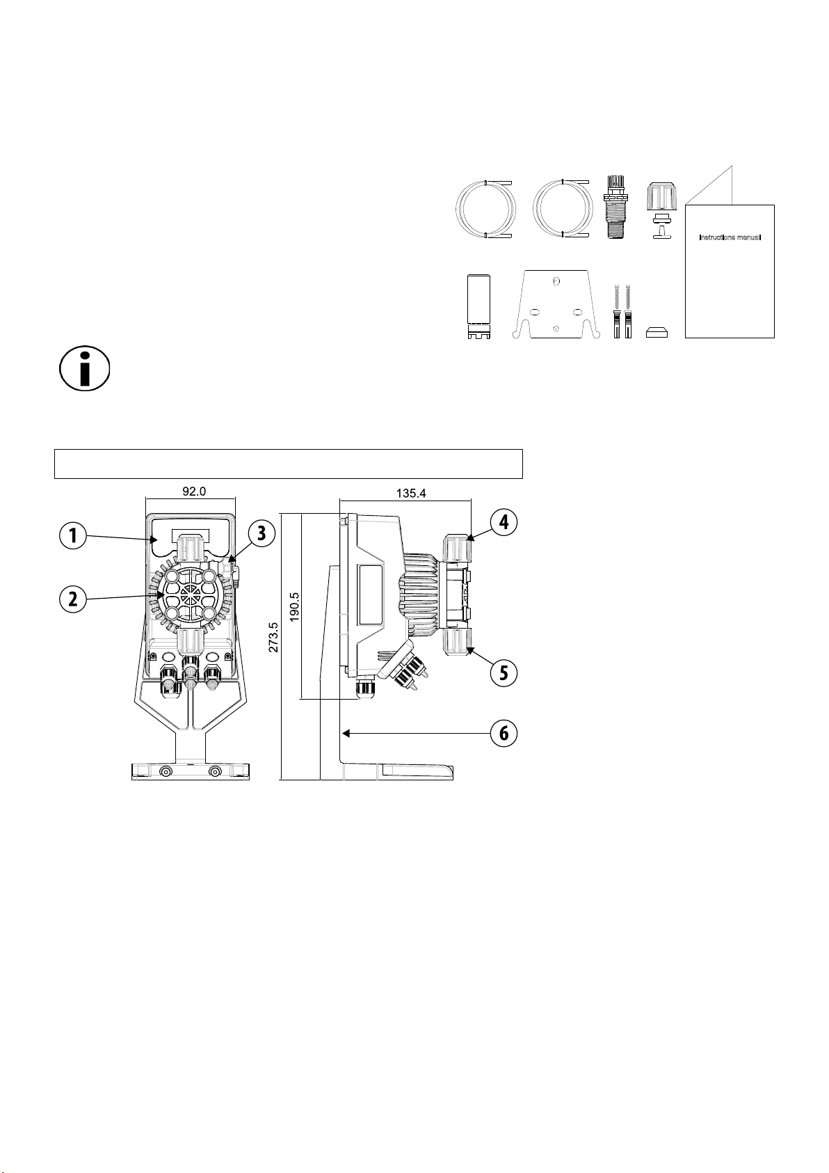
1
AB
E
C
G
I
F
D
H
INSTALLATION MANUAL AND COMMISSIONING GUIDE FOR THE
KOMPACT SERIES DOSING PUMPS
PACK CONTENTS:
A. Opaque tube for connecting the output from the pump
to the point of injection
B. Transparent tube for connecting the bleeder valve for
manual priming
C. Injection fitting
D. Tube connection kit
E. Foot filter
F. Wall fixing bracket
G. Anchor bolts for fixing the wall bracket
H. Pump body screws protection caps
I. Instruction Manual
FOR SPECIFIC HYDRAULIC FEATURES SEE THE LABEL ON THE PUMP
INTRODUCTION
The dosing pump consists of a control section containing the electronics and the magnet, and a hydraulic section, which
is always in contact with the liquid to be dosed.
Check the main specifications of your pump on the data plate
1Control panel
2Dosing head
3Valve for priming the pump
4Delivery connection
5Suction connection
6Support for base-plate (optional)
It is advisable to check the chemical compatibility between the product to be dosed and the materials with
which it will come into contact.
MATERIALS USED TO MAKE THE HEAD OF THE PUMP
•Casing: PVDF-T
•Valve: PVDF-T
•Balls: Ceramic
•Membrane: PTFE
TECHNICAL SPECIFICATIONS
•Weight: 1,5 Kg
•Power supply: 110 ÷ 230 Vac (50-60 Hz)
•Power consumption: 12 W
•Fuse: 2A 250V T 5x20
•Protection class: IP65
EM00136493 rev. 1.0 EN
2
READ CAREFULLY THE FOLLOWING WARNINGS BEFORE PROCEEDING
TO INSTALL OR CARRY OUT MAINTENANCE ON THE PUMP.
WARNING: ALWAYS DISCONNECT THE POWER SUPPLY BEFORE PROCEEDING TO INSTALL OR CARRY OUT
MAINTENANCE ON THE PUMP.
WARNING: WE RECOMMEND INSTALLING THE PUMP IN A VERTICAL POSITION TO ENSURE PROPER OPERATION.
WARNING: PRODUCT INTENDED FOR PROFESSIONAL USE ONLY, BY QUALIFIED PERSONNEL.
WARNING: THE MAINTENANCE OF THE PUMP MUST BE CARRIED OUT BY QUALIFIED AND AUTHORIZED
PERSONNEL.
-H2SO4SULPHURIC ACID Before dosing chemicals that could react with water it is necessary to dry all the internal
hydraulic parts.
-The ambient temperature must not exceed 40°C. The relative humidity must be lower than 90%. The pump protection
class is IP65. Do not install the pump in a place where it would be in direct sunlight.
-Secure the pump firmly into place in order to avoid excessive vibrations.
-The power-supply voltage available in the system and the working pressure must be compatible with those indicated on the
pump label.
WIRING CONNECTIONS
Input A
Power supply 110 ÷
230Vac (50 Hz)
The pump should be connected to a power supply
complying with the indications shown on the label on
the pump side. Failure to comply with the limits
indicated may cause damage to the pump.
These pumps have been designed to absorb minor
over voltages However, in order to prevent any
damage to the pump it is always preferable to avoid
connecting it to the same source of power as electrical
equipment that generates high voltages.
The connection to the three-phase 380V line MUST
always be made solely between phase and
neutral. No connections should
be made between phase and earth.
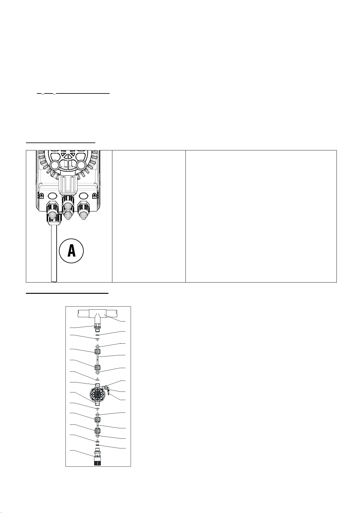
HYDRAULIC CONNECTIONS
13
4
6
3
12
5
2
11
6
4
8
4
6
6
43
14
5
10
9
7
5
5
1
1. Injection point
2. Injection coupling
3. Gasket
4. Washer holder
5. Pipe clamp
6. Ring nut
7. Delivery pipe (rigid)
8. Delivery coupling
9. Pumping body
10. Bleeding valve
11. Suction coupling
12. Suction hose (soft)
13. Foot filter
14. Bleeding valve coupling
EM00136493 rev. 1.0 EN
3
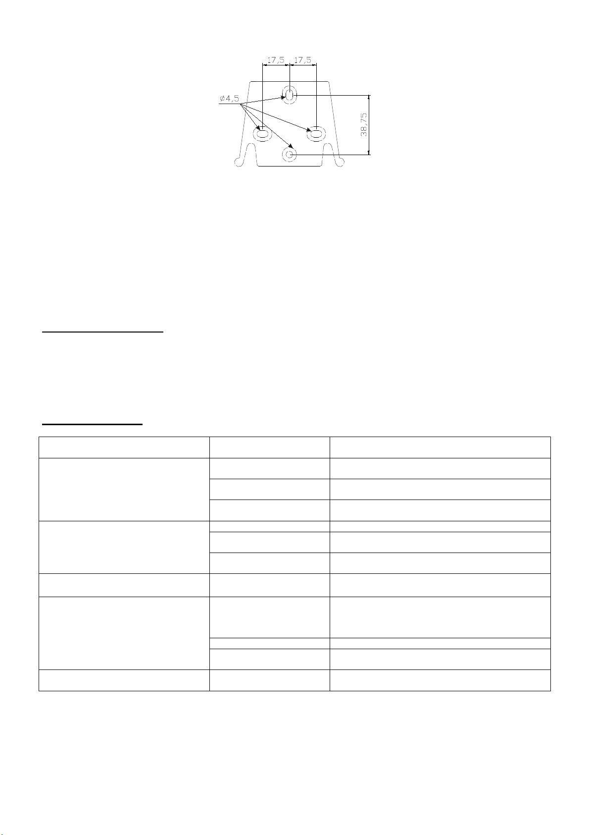
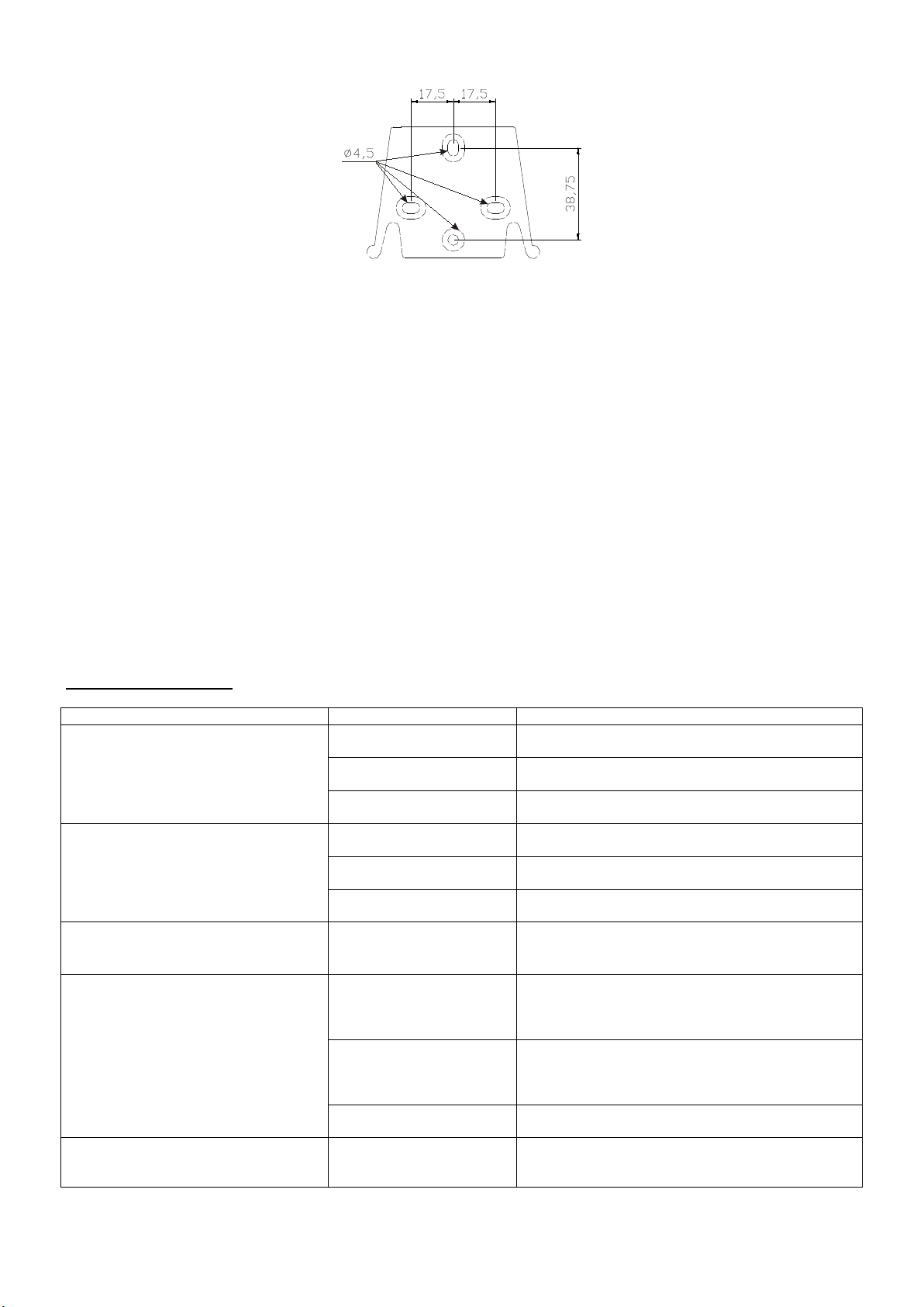
Drilling template for the wall bracket
After about 800 hours of operation, tighten the bolts of the pump body by using a tightening torque of 3 Nm.
In making the hydraulic connections it is necessary to comply with the following instructions:
-The BOTTOM FILTER should be installed at a distance of about 5-10 cm from the bottom, in order to avoid clogging;
-The installation with the pump below the liquid level is recommended for pumps with very low flow rates. In particular when
dosing products that have a tendency to develop gases (ex: sodium hypochlorite, hydrazine, hydrogen peroxide...)
-If it is necessary to use tubes longer than those supplied with the installation kit, they must always have the same
dimensions as those supplied with the pump. If the DELIVERY PIPE is exposed to direct sunlight, it is recommended the
use of a black UV-resistant pipe;
-It is advisable for the INJECTION POINT to be placed higher than the pump or the tank.;
-The INJECTION VALVE supplied with the pump, should always be installed at the end of the dosing-flow delivery line.
STARTING UP THE PUMP
Once you have checked all the above operations, you are ready to start the pump.
Priming
-Start the pump
-Open the priming coupling by turning the knob anticlockwise and wait for the liquid to flow out of the hose connected to it.
-Once you are sure that the pump is completely filled with liquid you can close the coupling and the pump begins to dose.
TROUBLESHOOTING
PROBLEM POSSIBLE CAUSE SOLUTION
The pump is running regularly but the
dosage was interrupted
The valves are clogged
Clean the valves or replace them if it’s not possible
to remove the deposits
Eccessive intake height
Position the pump or the tank so as to reduce the
intake height
The liquid is too viscous
Reduce the intake height or use a pump with a
higher flow rate
Insufficient flow rate
Leaky valves
Check the tightness of the nuts
The liquid is too viscous
Reduce the intake height or use a pump with a
higher flow rate
Partial clogging of the
valves
Clean the valves or replace them if it’s not possible
to remove the deposits
Irregular pump flow rate
Transparent PVC tube for
delivery
Use the opaque PE tube for delivery
The diaphragm is breaking
Excessive back pressure
Check the system pressure. Check if the injection
valve is clogged. Check if there is a clogging
between the discharge valves and the injection
point.
Operation without liquid
Check the presence of the foot filter (valve)
The diaphragm is not fixed
properly
If the diaphragm has been replaced, check its
proper tightening
The pump does not turn on
Insufficient power supply
Check if the values on the plate of the pump
correspond to those of the electrical network.
EM00136493 rev. 1.0 EN
4
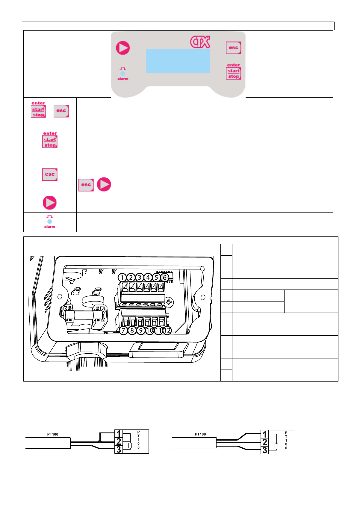
Control panel – KOMPACT DRP
+
To access the programming menu. (Press and hold down simultaneously for at least 3
seconds).
To start and stop the pump.
To disable the display notification in case of active level alarm condition (only alarm function),
flow alarm condition and memory.
In programming mode it functions as “enter”, to confirm the access and the changes to the
various menu levels.
To “escape” the various menu levels. Before exiting the programming mode you will be
prompted to save the changes.
Prolonged pressure displays the screen for the flow sensor calibration.
+ to change the contrast.
To scroll the menus or change the parameters in programming mode.
Prolonged pressure enables the priming.
Green LED flashes while dosing.
Red LED turns on in case of various alarm conditions.
CONNECTIONS DIAGRAM
Electrical connections
1 PT100 temperature probe input (see
the connection diagram)
2
3
4 Not Used
5 Pole - pH or Redox
probe input (pre-
wired with BNC )
6 Pole +
7 Level control probe input
8
9
Remote control input (start-stop)
10
11 Flow sensor input
12
2-wire PT100 connection diagram
3-wire PT100 connection diagram
EM00136493 rev. 1.0 EN
5
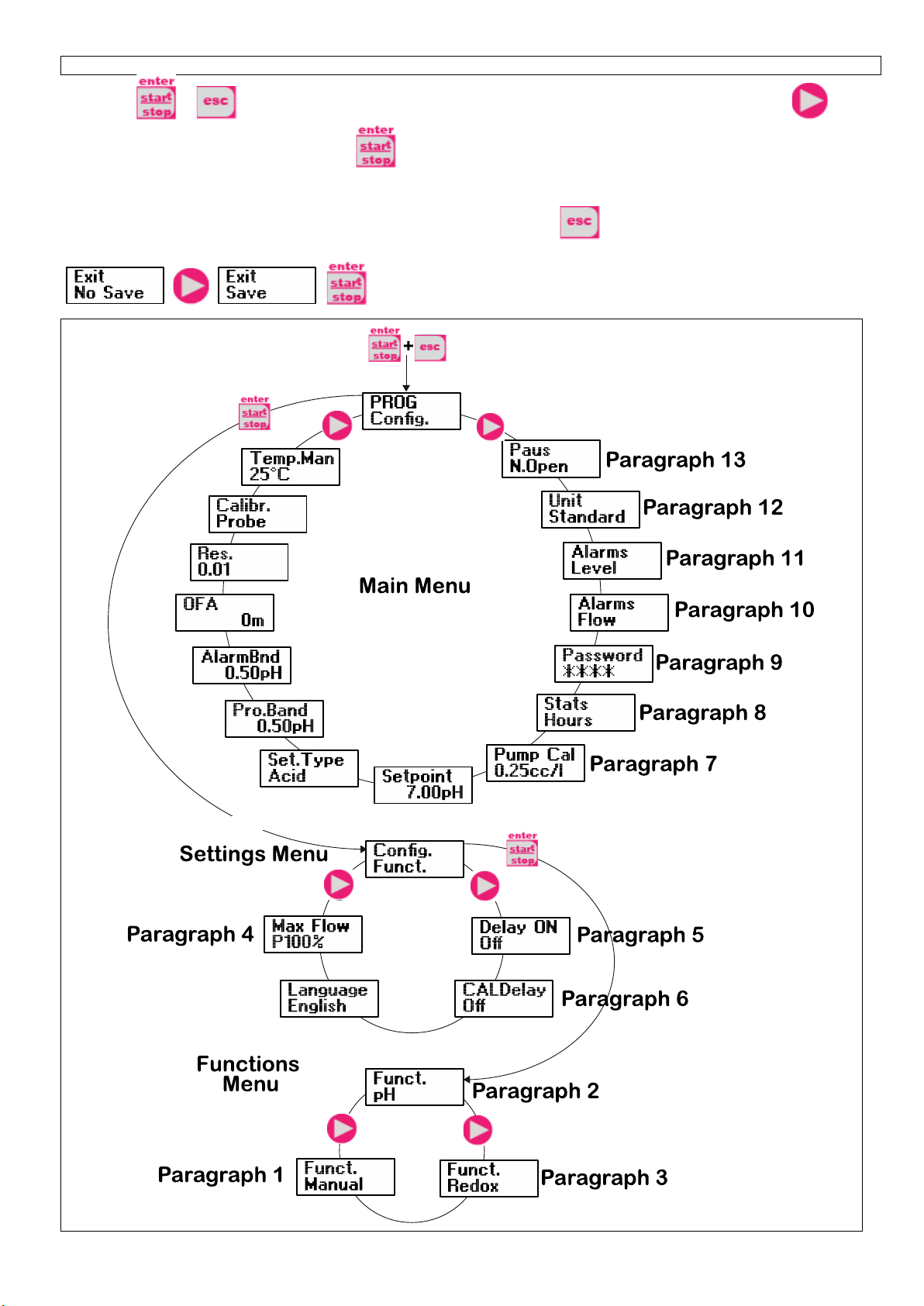
Kompact DRP Programming Menu
Press the + keys for more than three seconds to access the programming mode. Press the key
to scroll the menu items, then press the key to access the options. Whenever a menu item is editable, it
flashes.
By default the pump is set for constant mode. The pump automatically returns to operating mode after 1 minute of
inactivity. In this case, the data entered will not be saved. Press the key to exit the programming levels.
When you exit the programming mode, the display shows:
to confirm your choice.
EM00136493 rev. 1.0 EN
6
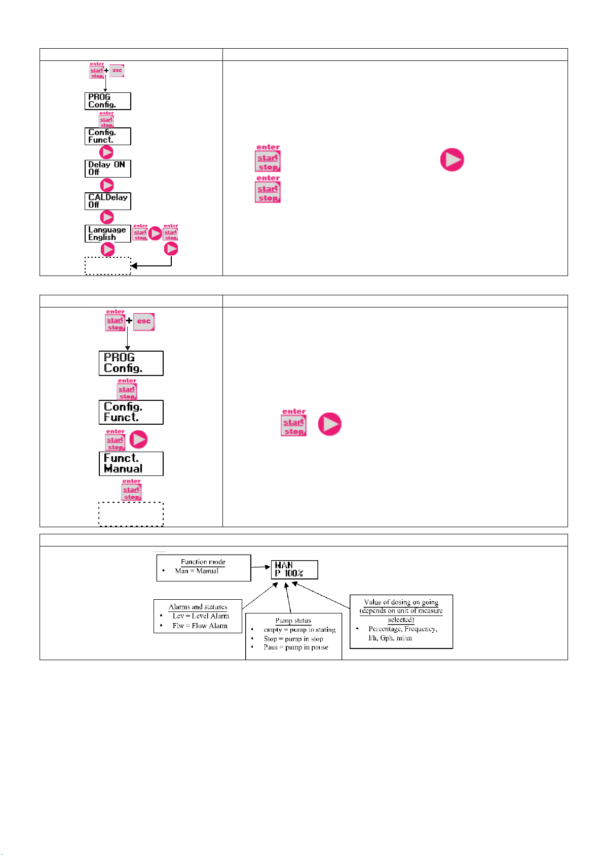
Setting the language
Programming
Operation
Allows you to set the language. By default the pump is set to English.
Press to access the item, and then press to set the language.
Press to confirm and return to the main menu.
Paragraph 1 –Manual dosing
Programming
Operation
The pump works in constant mode. The flow rate can be
adjusted manually
by pressing + simultaneously.
Display during operation

EM00136493 rev. 1.0 EN
7
Paragraph 2 – Proportional dosing for the pH measurement (factory default)
Programming
Operation
The pump measures and controls the pH value of a solution, by
programming the following parameters: set-point, set-point type
,
proportional band and alarm band.
Set-point type: acid
014
pH
s/m
max
flow-rate
Ala rm Ba nd Ala rm Ba nd
Proportional
Ba nd
set-point
AlarmOn
AlarmOn
Pump Off
PumpOn
Set-point type: alkaline
014
pH
s/m
max
flow-rate
Ala rm Ba nd Ala rm Ba nd
Proportional
Ba nd
set-point
AlarmOn
AlarmOn
Pump Off
PumpOn
Can also be programmed:
-The O.F.A. (Over Feed Alarm) time in minutes, a set period of time
after
which, if the measured pH does not reach the set-
point, an alarm signal
is activated.
-The resolution of the measurement (1 or 2 digits)
-Activation / deactivation of the calibration procedure
-Manual temperature value in °C (default) or °F
The maximum frequency can be changed during the operation by
pressing + simultaneously.
Display during operation

EM00136493 rev. 1.0 EN
8
Paragraph 3 – Proportional dosing for the Redox (O.R.P.) measurement
Programming
Operation
The pump measures and controls the Redox value of a solution, by
programming the following parameters: set-point, set-point type
,
proportional band and alarm band.
Set-point type: maximum
0
mV
s/m
max
flow-rate
Ala rm Ba nd Ala rm Ba nd
Proportional
Ba nd
set-point
AlarmOn
AlarmOn
Pump Off
P
umpOn
Set-point type: minimum
0
mV
s/m
max
flow-rate
Ala rm Ba nd Ala rm Ba nd
Proportional
Ba nd
set-point
AlarmOn
AlarmOn
Pump Off
PumpOn
Can also be programmed:
-The O.F.A. (Over Feed Alarm) time in minutes, a set period of
time after
which, if the measured Redox value does not reach the set-
point, an
alarm signal is activated.
-The resolution of the measurement (1 or 2 digits)
-Activation / deactivation of the calibration procedure
The maximum frequency can be changed during the operation by
pressing + simultaneously.
Display during operation
EM00136493 rev. 1.0 EN
9
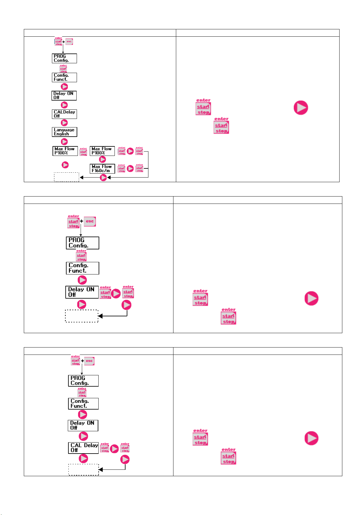
Paragraph 4 – Setting the Maximum Flow Rate
Programming
Operation
Allows you to set the maximum flow rate of the pump and
the programmed mode (% or frequency) is used as the
standard measurement unit when displaying the flow rate.
Press to access the item then press to set the
value. Press to confirm and return to the main
menu.
Paragraph 5 – Setting the Power On Delay
Programming
Operation
Allows you to set a pump operation delay at the start up of
the pump. This delay takes effect only if the pump is
switched off and then switched on by disconnecting the
power supply.
The delay can be disabled, Off (default) or can be set from 1
to 60 minutes.
With the delay enabled, during the set time the LED flashes
(1 sec On – 1 sec Off) and the display shows the countdown
in seconds. If the pump is in Stop mode the display shows
only the flashing LED. During the delay time the function can
be disabled by accessing the menu and setting the time to
Off.
Press to access the item, and then press to set
the value. Press to confirm and return to the main
menu.
Paragraph 6 – Setting the Calibration Delay
Programming
Operation
Allows you to set a pump operation delay after the probe
(Redox or pH) calibration
The delay can be disabled, Off (default) or can be set from 1
to 60 minutes.
With the delay enabled, during the set time the LED flashes
(1 sec On – 1 sec Off) and the display shows the countdown
in seconds. If the pump is in Stop mode the display shows
only the flashing LED. During the delay time the function can
be disabled by accessing the menu and setting the time to
Off.
Press to access the item, and then press to set
the value. Press to confirm and return to the main
menu.

EM00136493 rev. 1.0 EN
10
Paragraph 7 – Flow Rate Calibration
Programming
Operation
On the main menu appears the memorized cc/stroke value
.
You can perform the calibration in two modes:
MANUAL – insert manually the cc/stroke value using the
key and then confirm with the key.
AUTOMATIC – the pump runs 100 strokes,
which are
started by pressing the key, and at the end of the
strokes insert the amount aspirated by the pump using
the
key and confirm with the key.
The data entered will be used for
the calculation of the flow
rates.
Paragraph 8 – Statistics
Programming
Operation
On the main menu is displayed, in hours,
the operating time
of the pump; press to access other statistics:
- Strokes = the number of strokes performed by the pump
- Q.ta (L) = the quantity dosed from the pump expressed
in
liters; this information is calculated based on the
memorized
cc/stroke value
- Power = the number of pump activations
- Reset = press to reset the counters, select
(YES) or
(NO), then press to confirm.
Press to return to the main menu.

EM00136493 rev. 1.0 EN
11
Paragraph 9 – Password
Programming
Operation
By setting the password, the programming section can be
accessed to view all the setup parameters, but every time
you try to change the settings you will be prompted for the
password.
The flashing line indicates the editable number; press
to select the number (from 1 to 9), then press to select
the number to modify, and then press to confirm.
By setting “0000” (default), the password will be eliminated.
Paragraph 10 – Flow Alarm
Programming
Operation
Allows you to activate (deactivate) the flow sensor.
Once activated (On) by pressing the key,
you can set
the number of signals
the pump requires before starting the
alarm. Press and the number will start to flash; press
to set the value. Press to confirm. Press
to return to the main menu.
Paragraph 11 – Level Alarm
Programming
Operation
Allows you to set the pump for the level alarm activation,
with dosage operation interruption (Stop), or simple
activation of the alarm signal without dosage operation
interruption.
Press to access the item then press to set the
alarm type. Press to confirm. Press to return to
the main menu.
EM00136493 rev. 1.0 EN
12
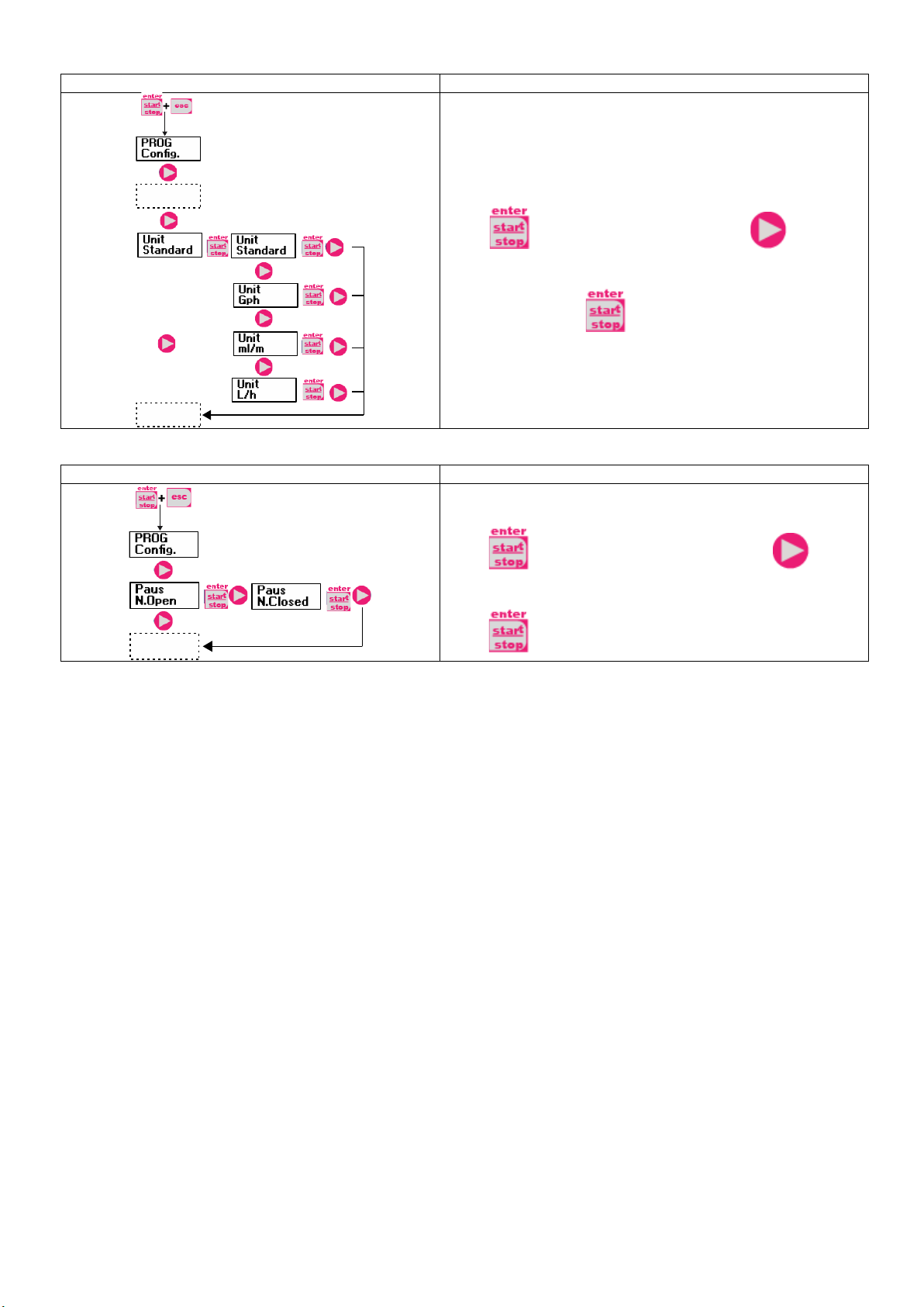
Paragraph 12 – Flow Rate Measurement Unit Display
Programming
Operation
Allows you to set the measurement unit of the displayed
dosage.
Press to access the item, then press
to set the
type of unit, L/h (Liter/hour), Gph (Gallons/hour), mL
/m
(milliliters/minute) or standard (% or frequency, according
to
the settings). Press
to confirm and return to the main
menu.
Paragraph 13 – Setting the Pause
Programming
Operation
Remote input to pause the pump.
By default, the system is set to Normally Open.
Press to access the item, and then press to set
the value (N. OPEN or N. CLOSED).
Press to confirm and return to the main menu.
EM00136493 rev. 1.0 EN
13
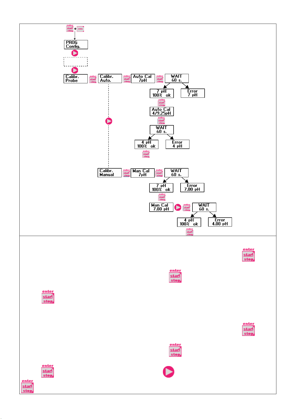
Calibration Menu
You can choose the automatic or manual calibration mode, in both cases the calibration at pH 7 is automatic.
-Automatic calibration:
When the display shows the value of the buffer solution, insert the probe into the bottle, press a
nd the
display will show the countdown of the 60 seconds required to complete the calibration.
If the quality of the
alignment is less than 50%, an error appears on the display; press
to exit the calibration (after 4 seconds the
pump will automatically exit the calibration); if the quality is higher than 50%, the value appears on the display;
pressing you will be prompted for the pH 4 or 9 buffer solution;
at this point the procedure is similar to the
previous calibration.
-Manual calibration:
When the display shows the value of the buffer solution, insert the probe into the bottle, press
and the
display will show the countdown of the 60 seconds required to complete the calibration.
If the quality of the
alignment is less than 50%, an error appears on the display; press to exi
t the calibration (after 4 seconds the
pump will automatically exit the calibration); if the quality is higher than 50%, the value appears on the display;
pressing on the display will flash the pH 7.00 value; press to insert the value of my solution, then press
to confirm and start the calibration procedure as described previously.

EM00136493 rev. 1.0 EN
14
Redox (O.R.P.) Calibration Menu
You can choose the automatic or manual mode.
-Automatic calibration:
When the display shows the value of the buffer solution, insert the probe into the bottle, press
and the
display will show the countdown of the 60 seconds required to complete the calibration.
If the quality of the
alignment is less than 50%, an error appears on the display; press
to exit the calibration (after 4 seconds the
pump will automatically exit the calibration); if the quality is higher than 50%, the value appears on the display;
press and the procedure is completed.
-Manual calibration:
When the display shows the value of the buffer solution, insert the probe into the bottle, press and the
display will show the value 465mV flashing, insert the probe into my solution, press to display the value of my
solution, then press to confirm and start the calibration procedure as described previously.
EM00136493 rev. 1.0 EN
15
Alarms
Dislay
Cause
Remedy
Alarm LED on
“Lev” icon flashing
End level alarm, without pump
operation interruption.
Restore the liquid level.
Alarm LED on
“Lev” and “Stop” icons flashing
End level alarm, with pump
operation interruption.
Restore the liquid level.
Alarm LED on
“Flw” icon flashing
Flow alarm activated, the pump has
not received from the flow sensor
the programmed number of signals. Press the key.
“OFA” icon flashing
“Stop” icon flashing
O.F.A. alarm
Press the key to stop the
flashing of the “Stop” icon, press
the key again to restart the pump.
“Alm” icon flashing
The value read by the probe is out
of the alarm band set
Check the "Alarm Band" parameter
for the correct settings in
programming mode.
“Cal” icon flashing
Probe not calibrated alarm
Perform the probe calibration
procedure.
EM00136493 rev. 1.0 DE
1
AB
E
C
G
I
F
D
H
INSTALLATIONS- UND INBETRIEBNAHMEANLEITUNG FÜR DIE
DOSIERPUMPE SERIE KOMPACT
Packungsinhalt:
A. Undurchsichtiger Schlauch für den Anschluss des
Pumpenausgangs an den Einspritzpunkt
B. Transparenter Schlauch für die Ansaugung, für den
Anschluss des Auslassventils und für die manuelle
Befüllung
C. Anschluss Einspitzung
D. Satz Schlauchanschlüsse
E. Bodenfilter
F. Bügel für Wandmontage
G. Dübel für die Montage des Wandbügels
H. Schraubenschutzkappen
I. Anleitung
HYDRAULISCHE BESONDERHEITEN FINDEN SIE UNTER DER BEZEICHNUNG AUF DER PUMPE
EINLEITUNG
Die Dosierpumpe besteht aus einer Steuereinheit, in der die Elektronik und der Magnet sowie ein Teil der Hydraulik
untergebracht sind, immer in Kontakt mit der zu dosierenden Flüssigkeit.
Prüfen Sie anhand der Angaben auf dem Typenschild die Haupteigenschaften
Ihrer Pumpe
1. Einstellbereich
2. Dosierkopf
3. Befüllventil
4. Druckanschluss
5. Ansauganschluss
6. Gestell für Unterbau (optional)
Wir empfehlen eine Prüfung der chemischen Kompatibilität zwischen dem dosierten Produkt und den
Kontaktmaterialien.
MATERIALIEN DES PUMPENKOPFES
•Pumpengehäuse: PVDF-T
•Ventile: PVDF-T
•Kugeln: Keramik
•Membran: PTFE
TECHNISCHE MERKMALE
•Gewicht: 1,5 Kg
•Stromversorgung: 110 ÷ 230 Vac (50-60 Hz)
•Leistungsaufnahme: 12 W
•Sicherung: 2A 250V T 5x20
•Schutzgrad: IP65
•Eingang Füllstandskontrolle: Trockenkontakt (on-off)
•Impulseingang: Trockenkontakt (on-off) Höchstfrequenz 80Hz

EM00136493 rev. 1.0 DE
2
VOR DER INSTALLATION ODER
WARTUNGSARBEITEN AN DER PUMPE AUFMERKSAM LESEN
ACHTUNG: VOR DER INSTALLATION ODER DER WARTUNG DER PUMPE IMMER ZUNÄCHST DIE VERSORGUNG
TRENNEN.
ACHTUNG: WIR EMPFEHLEN DIE INSTALLATION DER PUMPE IN EINER VERTIKALEN POSITION UM EINEN
ORDNUNGSGEMÄSSEN BETRIEB ZU GEWÄHRLEISTEN.
ACHTUNG: DAS PRODUKT IST AUSSCHLIESSLICH FÜR DEN PROFESSIONELLEN GEBRAUCH DURCH
QUALIFIZIERTES PERSONAL BESTIMMT.
ACHTUNG: DIE WARTUNG DER PUMPE DARF AUSSCHLIESSLICH DURCH QUALIFIZIERTES UND AUTORISIERTES
PERSONAL DURCHGEFÜHRT WERDEN.
-H2SO4SCHEFELSÄURE Vor der Dosierung chemischer Produkte, die mit Wasser reagieren können, müssen alle
internen Komponenten der Hydraulik getrocknet werden.
-Umgebungstemperatur unter 40°C. Relative Luftfeuchte unter 90%. Schutzgrad: IP65 Die Pumpe nicht so installieren, dass
sie direkt Sonnenstrahlen ausgesetzt ist.
-Die Pumpe gut befestigen, damit übermäßige Vibrationen vermieden werden.
-Versorgungsspannung und -druck der Anlage müssen mit den Angaben auf dem Etikett der Pumpe übereinstimmen.
ELEKTRISCHE ANSCHLÜSSE
Eingang A = Versorgung
110 ÷ 230 Vac (50-60
Hz)
Die Pumpe muss an eine Versorgung
angeschlossen werden, die mit den
Angaben auf dem Etikett an der Seite der
Pumpe übereinstimmen. Die
Nichtbeachtung dieser Vorschrift kann zu
Schäden an der Pumpe führen.
Die Pumpen wurden geplant, um geringe
Überspannungen absorbieren zu können.
Um Schäden an der Pumpe zu vermeiden,
sollte daher immer sicher gestellt werden,
dass sie keine Energiequelle zusammen mit
anderen elektrischen Apparaten nutzt, die
hohe Spannungen erzeugen.
Die Verbindung mit der 380V-
Dreiphasenleitung darf NUR zwischen
Phase und Neutralleiter vorgenommen
werden. Die Anschlüsse DÜRFEN NICHT
zwischen Phase und Erde erfolgen.
HYDRAULIKANSCHLÜSSE
13
4
6
3
12
5
2
11
6
4
8
4
6
6
43
14
5
10
9
7
5
5
1
1. Einspritzpunkt
2. Anschluss Einspritzung
3. Dichtung
4. Schlauchhalterung
5. Schlauchdurchführung
6. Gewindering
7. Druckschlauch (starr)
8. Druckventil
9. Pumpengehäuse
10. Ablassventil
11. Ansaugventil
12. Ansaugschlauch (weich)
13. Bodenfilter
14. Anschluss Ablassventil
EM00136493 rev. 1.0 DE
3
Bohrschablonen Wandbügel
Nach etwa 800 Betriebsstunden die Bolzen des Pumpengehäuses mit einem Anzugsmoment von 3 Nm anziehen.
Zum Durchführen derWasseranschlüsse müssen folgende Hinweise beachtet werden:
-Den BODENFILTER etwa 5-10cm über dem Boden installieren, um eventuelle Ablagerungen zu vermeiden
-Die Installation unter dem Flüssigkeitsstand wird bei Pumpen mit sehr geringer Fördermenge empfohlen. Insbesondere für
die Dosierung von Produkten, die Gase entwickeln (z.B. Natriumhypochlorit, Hydrazin, Wasserstoffperoxid,...).
-Bei Schläuchen, die länger als die im Installationssatz enthaltenen sind, ist es wichtig, dass diese dieselben Maße wie die
mit der Pumpe gelieferten aufweisen. Wenn die DRUCKLEITUNG Sonnenstrahlung ausgesetzt ist, empfiehlt sich der
Einsatz eines schwarzen, UV-beständigen Schlauchs;
-Der EINSPRITZPUNKT sollte höher als die Pumpe oder der Tank liegen;
-Das EINSPRITZVENTIL, das mit der Pumpe geliefert wird, muss immer am Ende der Druckleitung des Dosierungsflusses
installiert werden.
START
Nach der Durchführung aller zuvor beschriebenen Schritte ist die Pumpe für den Start bereit.
Befüllen
-Die Pumpe starten
-Den Befüllanschluss durch Drehen des Knaufs entgegen dem Uhrzeigersinn öffnen und warten, bis die Flüssigkeit aus der
angeschlossenen Leitung tritt.
-Nachdem sicher gestellt wurde, dass die Pumpe ganz gefüllt ist, kann der Anschluss wieder geschlossen werden und die
Pumpe beginnt mit der Dosierung.
PROBLEMBEHEBUNG
Störung
Mögliche Ursache
Lösung
Die Pumpe funktioniert normal, aber die
Dosierung wurde unterbrochen.
Verstopfung der Ventile
Die Ventile reinigen oder, wenn es nicht möglich ist,
die Verkrustungen zu entfernen, ersetzen
Übermäßige Ansaughöhe
Die Pumpe oder den Tank so positionieren, dass die
Ansaughöhe reduziert wird
Flüssigkeit zu viskos
Die Ansaughöhe reduzieren oder eine Pumpe mit
höherer Fördermenge nutzen
Unzureichende Fördermenge
Leckage der Ventile
Kontrollieren, ob die Gewinderinge korrekt
angezogen sind
Flüssigkeit zu viskos
Eine Pumpe mit höherer Fördermenge nutzen oder
die Ansaughöhe reduzieren
Teilweise Verstopfung der
Ventile
Die Ventile reinigen oder, wenn es nicht möglich ist,
die Verkrustungen zu entfernen, ersetzen
Unregelmäßige Fördermenge der
Pumpe
Für die Druckleitung wird
ein transparenter PVC-
Schlauch genutzt
Einen undurchsichtigen PE-Schlauch für die
Druckleitung nutzen
Membran ist kaputt
Zu hoher Gegendruck
Den Druck der Anlage prüfen. Prüfen, ob das
Einspritzventil verstopft ist. Prüfen, ob zwischen den
Druckventilen und dem Einspritzpunkt
Verstopfungen vorhanden sind.
Betrieb ohne Flüssigkeit
Prüfen, ob der Bodenfilter (das Ventil) vorhanden
ist. Eine Füllstandssonde verwendet, die die Pumpe
blockiert, wenn das chemische Produkt im Tank zu
Ende geht
Membran nicht richtig
befestigt
Bei Ersatz der Membran prüfen, dass diese wieder
richtig befestigt wird.
Die Pumpe geht nicht an
Unzureichende Versorgung
Prüfen, ob die Werte auf dem Typenschild der
Pumpe mit denen des Stromnetzes
übereinstimmen.
This manual suits for next models
3
Table of contents
Languages:
Other CTX Water Pump manuals


Popular Water Pump manuals by other brands


Xylem
Xylem LOWARA e-SV Series Additional Installation, Operation and Maintenance Instructions

Grundfos
Grundfos CR 1 instructions

Pacific hydrostar
Pacific hydrostar PacificHydrostar 2" Gasoline Powered Clear Water... manual

GORMAN-RUPP PUMPS
GORMAN-RUPP PUMPS 0 Series Installation, operation, and maintenance manual with parts list

Graco
Graco Series A Repair

Ingersoll-Rand
Ingersoll-Rand ARO EVO EP20-P Series Operator's manual