Cub Cadet 190-004 User manual

IMPORTANT: Read safety rules and instructions carefully before operating equipment.
CUB CADET CORP. P.O. BOX 368023 CLEVELAND, OHIO 44136-9722
Model 190-004
42” Hydraulic
Tiller Attachment
REQUIRED FOR USE:
Weight Kit Bracket
(190-413-100)
Suitcase Weights
(190-390-100)
Three Point Hitch
(190-207-100)
PRINTED IN U.S.A.
Operator’s Manual
FORM NO.
770-10369A
(6/00)
ECO No. 01677

2
TABLE OF CONTENTS
Content Page
Important Safe Operation Practices................................................................... 3
Slope Gauge ..................................................................................................... 6
To the Owner .................................................................................................... 7
Loose Parts........................................................................................................ 7
Assembling the Tiller.......................................................................................... 7
Preparing the Tractor ........................................................................................ 9
Mounting the Tiller ............................................................................................. 9
Know the Tiller ................................................................................................... 11
Operating the Tiller ............................................................................................ 13
Maintenance ...................................................................................................... 15
Storage .............................................................................................................. 17
Troubleshooting ................................................................................................. 19
FINDING MODEL NUMBER
This Operator’s Manual is an important part of your new tiller attachment. It will help you assemble, prepare
and maintain the unit for best performance. Please read and understand what it says.
Before you start assembling your new equipment, please locate the model plate on the
equipment and copy the information from it in the space provided below. The information on
the model plate is very important if you need help from your local authorized Cub Cadet
dealer.
You can locate the model number by looking at the left side of the tiller frame near the top. A sample model
plate is explained below.
CALLING WARRANTY SERVICE
If you have difficulty assembling this product or have any questions regarding the controls, operation or
maintenance of this unit, please call the Customer Dealer Referral Line.
Call 1-(800)-528-1009 to locate your nearest Cub Cadet dealer. Before contacting your local
dealer, be sure to have your unit’s model number and serial number ready. See previous
section to locate this information.
Copy the model number here:
Copy the serial number here:
CUB CADET CORP.
CLEVELAND, OHIO 44136
P. O. B O X 3 6 8 0 2 3
(Model Number) (Serial Number)

3
SECTION 1: IMPORTANT SAFE OPERATION PRACTICES
WARNING: This symbol points out important safety instructions which, if not followed, could endanger
the personal safety and/or property of yourself and others. Read and follow all instructions in this
manual before attempting to operate this machine. Failure to comply with these instructions may result
in personal injury. When you see this symbol—heed its warning.
DANGER: This machine was built to be operated according to the rules for safe operation in this
manual. As with any type of power equipment, carelessness or error on the part of the operator can
result in serious injury. This machine is capable of amputating hands and feet, and throwing objects.
Failure to observe the following safety instructions could result in serious injury or death.
General Operation
• Read this operator’s manual carefully in its entirety
before attempting to assemble this machine. Read,
understand, and follow all instructions on the
machine and in the manual(s) before operation. Be
completely familiar with the controls and the proper
use of this machine before operating it. Keep this
manual in a safe place for future and regular
reference and for ordering replacement parts.
•Thismachineisaprecisionpieceofpower
equipment, not a plaything. Therefore, exercise
extreme caution at all times. Your unit has been
designed to perform one job: to till soil. Do not use it
for any other purpose.
•Neverallowchildrenunder14yearsoldtooperate
this machine. Children 14 years old and over should
read and understand the operation instructions and
safety rules in this manual and should be trained
and supervised by a parent. Only responsible
individuals who are familiar with these rules of safe
operation should be allowed to use your machine.
• Thoroughly inspect the area where the equipment is
to be used. Remove all stones, sticks, wire, bones,
toys and other foreign objects which could be
picked up and thrown by the tiller tines in any
direction which could cause serious personal injury
to the operator or any others allowed in the area.
Plan your tilling pattern to avoid discharge of
material toward roads, sidewalks, bystanders and
the like. To help avoid tine contact or a thrown
object injury, keep children, bystanders and helpers
at least 75 feet from the tiller attachment while it is in
operation. Stop tiller if anyone enters the area.
• Always wear safety glasses or safety goggles
during operation or while performing an adjustment
or repair to protect eyes from foreign objects that
may be thrown from the machine in any direction.
•Wearsturdy,rough-soledworkshoesandclose-
fitting slacks and shirts. Shirts and pants that cover
the arms and legs and steel-toed shoes are
recommended. Loose fitting clothes and jewelry
can be caught in movable parts. Never operate a
unit in bare feet, sandals, slippery or light weight
(e.g. canvas) shoes.
• Do not put hands or feet near or under rotating
parts. Keep clear of the tiller tines at all times as the
rotating tines can cause injury.
• Never operate the tiller without the rear deflector in
its proper place.
• Disengage the PTO and raise the tiller attachment
when crossing gravel drives, walks, or roads.
•Watchfortrafficwhenoperatingnearorcrossing
roadways. This machine is not intended for use on
any public roadway.
• Do not operate while under the influence of alcohol
or drugs.
•Usetillerattachmentindaylightoringoodartificial
light only.
•Nevercarrypassengers.
• Slow down before turning. Operate the machine
smoothly. Avoid erratic operation and excessive
speed.
•Useaslowgroundspeedwhentillingsoilforthe
first time. Fast speeds may cause you to lose
control and may also damage the machine.
• Disengage the PTO and raise the tiller attachment
before shifting into reverse and backing up. Always
look down and behind before and while backing up
to avoid a back-over accident.
• Disengage the PTO and raise the tiller attachment
before making sharp turns. Leaving the tiller
lowered and engaged may adversely affect the
steering and control of the tractor.
•Useextracautionwhenmakingturns,especiallyin
tight areas or around obstacles. The tiller
attachment extends beyond the back of the tractor
and could strike an adjacent object (e.g. tree, fence,
bystander etc.) which could damage the machine or
cause personal injury.
•Checkoverheadclearancescarefullybeforedriving
under power lines, wires, bridges, low hanging tree
branches, before entering or exiting buildings, or
any other situation where the operator may be
struck or pulled from the unit, which could result in
serious personal injury.
• Disengage the PTO and raise the tiller attachment
when not in use.
• Never leave a running machine unattended. Always
disengage PTO, place transmission in neutral, set

4
parking brake, turn engine off and remove key
before dismounting.
•DisengagethePTO,stoptheengineandwaituntil
the tiller comes to a complete stop before making
any repairs, adjustments, or removing any rocks or
debris.
•Useextracautionwhenloadingorunloadingthe
machine into a trailer or truck. A tractor with a tiller
attachment should not be driven up or down a ramp
onto a trailer or truck under power, the unit could tip
over causing serious personal injury. The unit must
be pushed manually to load or unload properly.
• Follow all manufacturer’s recommendations for use
of counterweights to improve machine stability.
•Ifsituationsoccurwhicharenotcoveredinthis
manual, use care and good judgment. Contact your
dealer for assistance. Telephone 1-800-528-1009
for the name of your nearest dealer.
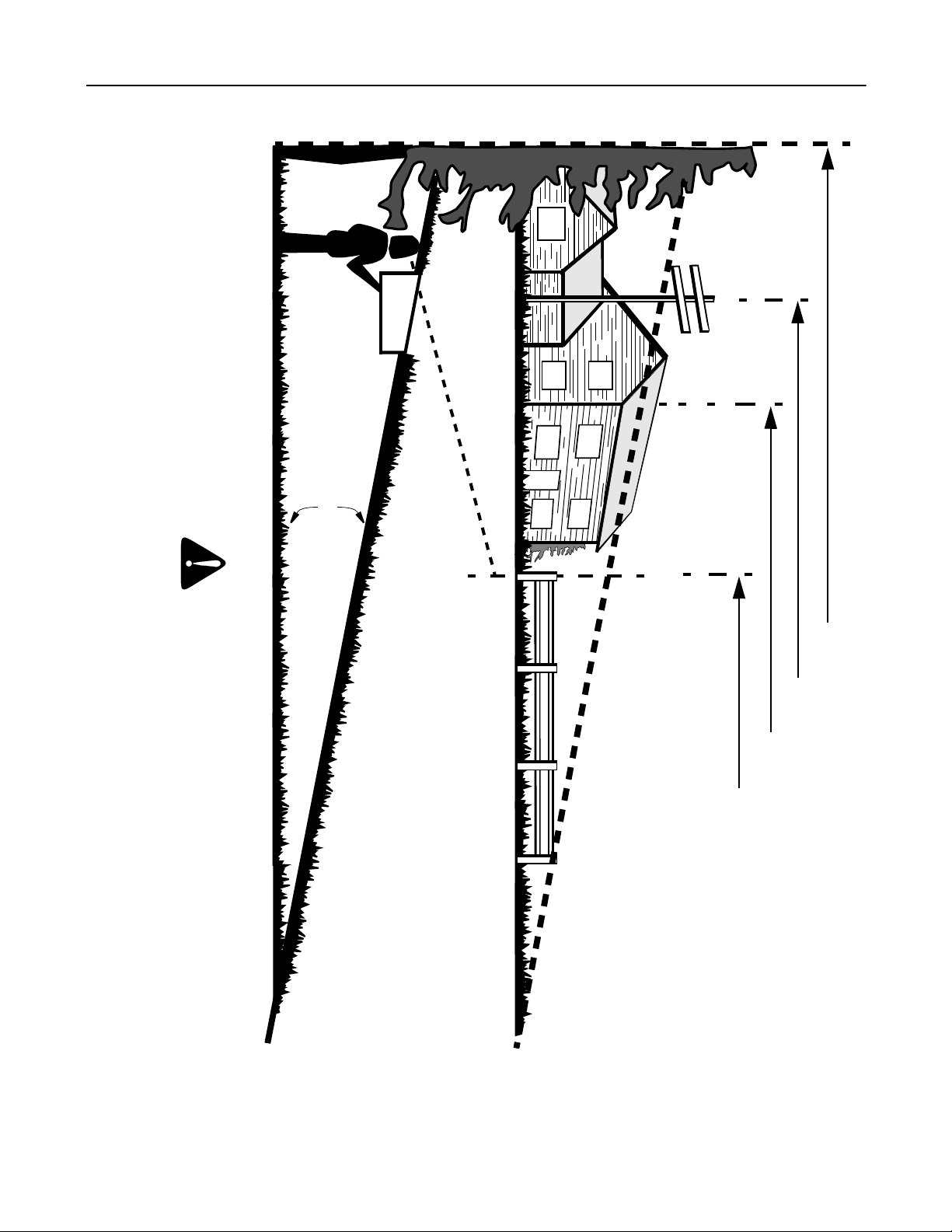
Slope Operation
Slopes are a major factor related to loss of control and
tip-over accidents which can result in severe injury or
death. Operation on slopes requires extra caution. If
you cannot back up the slope or if you feel uneasy on it,
do not till it. For your safety, use the slope gauge
included as part of this manual to measure slopes
before operating this unit on a sloped or hilly area. If the
slope is greater than 10 degrees as shown on the slope
gauge, do not operate this unit on that area or serious
injury could result.
Do:
•Tillupanddownslopes,notacross.Exercise
extreme caution when changing direction on slopes.
• Watch for holes, ruts, bumps, and hidden objects
(e.g. rocks etc.) which can be under the soil.
Uneven terrain could overturn the machine which
may cause personal injury.
•Useslowspeed.Choosealowenoughspeed
setting so that you will not have to stop or shift while
on the slope. Always keep the machine in gear
when going down slopes to take advantage of the
engine braking action.
•Keepallmovementsonslopesslowandgradual.
Do not make sudden changes in speed or direction.
Rapid engagement or braking could cause the front
of the machine to lift and rapidly flip over backwards
which could cause serious personal injury.
•Avoidstartingandstoppingonaslope.Iftireslose
traction, Disengage the PTO and proceed slowly
straight down the slope.
•Useextracarewiththetillerattachmentasitcan
change the stability of the machine.
• Follow all manufacturer’s recommendations for
wheel weights or counterweights to improve the
stability of the machine.
Do Not:
•Donotturnonslopesunlessnecessary;then,turn
slowly and gradually downhill, if possible.
• Do not till near drop-offs, ditches or embankments.
The machine could suddenly overturn if a wheel or
the attachment is over the edge, or if the edge
caves in.
• Do not operate machine on wet grass. Reduced
traction could cause sliding and loss of control of the
machine.
•Donottrytostabilizethemachinebyputtingyour
foot on the ground.
•Donottillslopesgreaterthan10degreesasshown
on the slope gauge.
Children
Tragic accidents can occur if the operator is not alert to
the presence of children. Children are often attracted to
the machine and the tilling activity. They do not
understand the dangers. Never assume that children
will remain where you last saw them.
•Keepchildrenoutofthetillingareaandunderthe
watchful care of a responsible adult other than the
operator.
•Bealertandturnthemachineoffifachildentersthe
area.
•Beforeandwhilemovingbackwards,lookbehind
and down for small children.
•Useextremecarewhenapproachingblindcorners,
doorways, shrubs, trees, or other objects that may
obscure your vision of a child who may run into the
machine.
•Nevercarrychildren,evenwiththeattachment
disengaged. They may fall off and be seriously
injured or interfere with safe machine operation.
• Keep children away from hot or running engines.
They can suffer burns from a hot muffler.
• Remove key when machine is unattended to
prevent unauthorized operation.
Never allow children under 14 years old to operate a
power mower. Children 14 years old and over should
read and understand the operation instructions and
safety rules in this manual and should be trained and
supervised by a parent.
Service
Safe Handling of Gasoline:
To avoid personal injury or property damage use
extreme care in handling gasoline. Gasoline is
extremely flammable and the vapors are explosive.
Serious personal injury can occur when gasoline is
spilled on yourself or your clothes which can ignite.
Wash your skin and change clothes immediately.
• Use only an approved gasoline container.
•Extinguishallcigarettes,cigars,pipesandother
sources of ignition.
• Never fuel machine indoors because flammable
vapors will accumulate in the area.

5
•Neverremovegascaporaddfuelwhiletheengine
is hot or running. Allow engine to cool at least two
minutes before refueling.
•Neveroverfillfueltank.Filltanktonomorethan½
inch below bottom of filler neck to provide space for
fuel expansion.
•Replacegasolinecapandtightensecurely.
• If gasoline is spilled, wipe it off the tractor’s fender.
Move unit to another area. Wait 5 minutes before
starting the engine.
•Neverstorethemachineorfuelcontainerinside
where there is an open flame, spark, or pilot light as
on a water heater, space heater, furnace, clothes
dryer, or other gas appliances.
•Toreducefirehazard,keepmachinefreeofgrass,
leaves, or other debris build-up. Clean up oil or fuel
spillage and remove any fuel soaked debris.
•Allowmachinetocoolatleast5minutesbefore
storing.
General Service:
•Neverrunanengineindoorsorinapoorly
ventilated area. Engine exhaust contains carbon
monoxide, an odorless and deadly gas.
•Beforecleaning,repairing,orinspecting,make
certain the tines and all moving parts have stopped.
Disconnect the spark plug wire and ground against
the engine to prevent unintended starting.
• Never attempt to make adjustments or repairs to the
machine while the engine is running.
•Nevercheckforleaksinthehydrauliclineswith
your hands. Hot, high pressure fluid can escape
through a pin hole leak and cause serious injury by
puncturing the skin and causing blood poisoning.
• Muffler, engine and belt guards become hot during
normal operation and can cause a burn. Hydraulic
hoses, fittings and fluid also become hot during
normal operation. Allow the machine, tiller
attachment, and its related hardware time to cool
before cleaning, repairing, or inspecting.
• Check the tine mounting bolts at frequent intervals
for proper tightness. Also, visually inspect tines for
damage (e.g., bent, cracked, worn etc.) Replace
tines with the original equipment manufacture’s
(O.E.M.) tines only, listed in this manual. “Use of
parts which do not meet the original equipment
specifications may lead to improper performance
and compromise safety!”
•Tillertinesaresharpandcancauseseriousinjury.
Wrap the tines or wear gloves, and use extra
caution when servicing them.
•Keepallnuts,bolts,andscrewstighttobesurethe
equipment is in safe working condition.
•Nevertamperwithsafetydevices.Checktheir
proper operation regularly. Use all guards as
instructed in this manual.
•Afterstrikingaforeignobject,stoptheengine,
disconnect the spark plug wire and ground against
the engine. Thoroughly inspect the machine for any
damage. Repair the damage before starting and
operating.
•Checkbrakeoperationfrequentlyasitissubjected
to wear during normal operation. Adjust and service
as required.
•Ifthetractorortillerattachmentshouldbeginto
vibrate abnormally, stop the engine and check over
the equipment immediately for the cause. Abnormal
vibration is a warning of a problem.
•Donotchangetheenginegovernorsettingor
overspeed the engine.
• Observe proper disposal laws and regulations.
Improper disposal of fluids and materials can harm
the environment.
•Maintainorreplacesafetyandinstructionlabels,as
necessary.
Your Responsibility
Restrict the use of this power machine to persons who read, understand and follow the warnings and
instructions in this manual and on the machine. The safety label on the equipment is reproduced
below. Take a moment to study the label before operating the unit. Always maintain safety while
operating or servicing the equipment.

6
SECTION 2: SLOPE GAUGE
10°
SIGHT AND HOLD THIS LEVEL WITH A VERTICAL TREE
A POWER POLE
A CORNER OF A BUILDING
OR A FENCE POST
FOLDONDOTTEDLINE,REPRESENTINGA10°SLOPE
Do not use the tiller attachment and tractor on inclines with a slope in excess of 10 degrees (a rise of approximately 2 feet every
10 feet). A riding mower could overturn and cause serious injury.
Operate RIDING mowers up and down slopes, never across the face of slopes.
WARNING

7
SECTION 3: TO THE OWNER
Model 190-004-100, 42-inch hydraulic tiller attachment is designed for use on Series 3000 Garden Tractors only. It
will NOT fit nor operate properly or safely on ANY other tractor. Using this tiller attachment requires the use of the
weight kit bracket 190-413-100, suitcase weights part number 190-390-100 (two weights are required and three are
recommended), and the three point hitch assembly, model 190-207-100. These parts are available through an
authorized Cub Cadet dealer.
The instructions in this manual are divided into sections. Carefully read all sections and study the illustrations to
ensure proper installation and usage of this attachment. Read and observe all WARNING and CAUTION
statements. They are included to provide for the protection of the equipment installer and user, and to ensure the
prolonged service life of the equipment.
References to LEFT and RIGHT indicate the left and right sides of the tractor and tiller attachment when facing
forward in the operator’s position. Reference to the FRONT indicates the grille end of the tractor and reference to
the REAR dictates the drawbar end where the tiller attaches.
SECTION 4: LOOSE PARTS
The tiller attachment is shipped with the following loose parts in the carton. Remove all the loose parts from the
carton before discarding it. See Figure 1 to identify the parts, noting that these parts may be referred to again in the
following sections of the manual.
Figure 1
SECTION 5: ASSEMBLING THE TILLER
Hydraulic Pump Assembly
The hydraulic pump assembly is shipped complete with
a drive shaft, mounting brackets, and the hardware that
is necessary to mount it to the tractor.
The two hydraulic hoses are packaged separately from
the hydraulic pump assembly and need to be attached
to the fittings on the hydraulic pump. Both hoses have
regular female fittings on the end that will attach to the
hydraulic pump. The opposite end of the hoses have a
right angle fitting on the large diameter hose and a
regular female fitting on the small diameter hose.
These hydraulic hoses will attach to male fittings on
both the hydraulic pump assembly and the tiller
assembly.
NOTE: Before installing the hydraulic hoses, make
certain that the hose hooks are aligned on the hydraulic
hose sleeve as shown in Figure 2.
To connect the hydraulic hoses to the hydraulic pump
assembly:
•Locate both male hydraulic fittings on the hydraulic
pump. Notice that the fittings are not the same
diameter.
Hydraulic Pump Assembly
Rear Tine Shield
(for use w/out roller)
Tiller Frame w/Roller
Hydraulic Hoses

8
Figure 2
•Thread the end of the large diameter hose with the
straight fitting, onto the male end of the hydraulic
pump by hand, making sure to not cross thread the
connectors.
•Once the fitting is hand tight, use two wrenches to
tighten the connection. One wrench will prevent the
hose from spinning while tightening, and the other
will be used to tighten the connectors together.
Tighten firmly.
•Repeat this step for the small diameter hydraulic
hose.
Tiller Frame and Roller Assembly
The tiller frame and the roller come shipped as an
assembly. The tiller does not get shipped with the
hydraulic fluid that is required to drive the tiller. Before
adding fluid, the two hydraulic hoses that are attached
at one end to the hydraulic pump assembly, need to be
installed on the tiller.
Figure 3
The large diameter hydraulic hose with the right angle
fitting needs to be attached to the tiller frame. There is a
male fitting on the front, right side of the tiller frame.
Attach the large hydraulic hose to the tiller frame using
the same method that was used when attaching to the
hydraulic pump. Refer to Figure 4.
The small diameter hydraulic hose coming from the
hydraulic pump has to be attached to the hydraulic
control valve. Locate the male fitting on the side of the
hydraulic control valve. Refer to Figure 3. Attach the
hydraulic hose using the same procedure that was
used to attach this hose to the hydraulic pump.
Figure 4
There is a short hydraulic hose that is connected to the
hydraulic motor on one end that was removed from the
hydraulic control valve for shipping (refer to Figure 3).
After installing the small diameter hydraulic hose to the
control valve, attach the short hose to the male fitting on
top of the control valve.
Hydraulic Fluid
The tiller attachment operates using hydraulic fluid. The
fluid should be added to the tiller after the hydraulic
hoses are connected. Recommended fluids to be used
in this tiller include Mobile 424, Texaco TDH, Shell
Donax, Farmland TF, Citgo TF, Sun Tractor Fluid,
Amoco 1000, and Shell TTF.
Remove the dipstick/reservoir cap and add six gallons
of hydraulic fluid as noted above. Replace the dipstick.
Recheck the hydraulic fluid after the tiller has been
mounted on the tractor and the hydraulic pump has
been engaged. The hydraulic hoses, hydraulic pump,
hydraulic motor, control valve, and the hydraulic filter
will all fill up with hydraulic fluid once the hydraulic
pump has been engaged. Hence, the fluid level will
then need to be rechecked and more fluid will need to
be added to achieve the proper fluid level of the
reservoir.
NOTE: Refer to the maintenance section for
information pertaining to changing the hydraulic fluid
and filter after use.
Small Diameter
Large Diameter Male Fitting
Hydraulic Pump Assembly
Hydraulic Pump
Male Fitting
Short Hose Hook
Long Hose Hook
Hydraulic Hose Sleeve
Attach Large Diameter
Attach Small
Diameter Hose Hydraulic Hose
Connect Together
Dipstick/Reservoir Cap
Control
Valve
Hydraulic Motor
Short Hose
Long Hose Hook
Large Diameter
Hydraulic Hose
Small Diameter
Hydraulic Hose
Right Angle Fitting
Hose Sleeve

9
SECTION 6: PREPARING THE TRACTOR
NOTE: References to LEFT and RIGHT indicate the left
and right sides of the tractor and tiller attachment when
facing forward in the operator’s position.
NOTE: If the tractor is equipped with a mower deck,
remove it now. Refer to the mower deck’s operator’s
manual for instruction on removing the mower deck.
IMPORTANT: Using this tiller attachment requires the
use of weight kit bracket 190-413-100, suitcase weights
part number 190-390-100 (two weights required), and a
three point hitch assembly, model 190-207-100.
Without the front weights installed, steering can
become extremely difficult and there is potential for
backwards tip over on uneven surfaces. Install these
components while preparing the tractor for tilling.
Attaching the Mounting Brackets
The hydraulic pump assembly attaches to the tractor
using brackets that are permanently affixed to the
tractor’s frame. These brackets are shipped with the
hydraulic pump assembly. The hardware to mount the
brackets to the tractor is shipped attached to the
brackets and will need to be removed before installing.
The front mounting brackets will require two 1/2”
wrenches to install on the tractor.
•While holding the front mounting brackets against
the outside of the frame rail, install the mounting
bolts. These should be mounted with the threads
toward the inside of the frame. Refer to Figure 5 to
determine the relation of the brackets to the frame.
•Thread the locking nut onto the bolt threads and
tighten. Repeat this step on the other side. These
brackets will not need to be removed when using a
mower deck.
The rear mounting brackets for the hydraulic pump
assembly use an existing lock nut and bolt which is
mounted to the tractor’s frame. This bolt is used on the
tractor to hold the lift links to the tractor’s frame.
Remove it before attaching the rear mounting brackets.
Figure 5
•To remove the mounting hardware from the tractor,
use a 3/4”wrench on the locking nut, and a 15/16”
wrench on the head of the bolt and loosen. Refer to
Figure 5 for the correct location of the hardware to
be removed.
•Set this hardware aside, it will be reused.
Installing the rear mounting brackets will require the
tools and hardware removed in the previous step.
•Working on either side of the tractor, position the
rear mounting bracket against the tractor’s frame as
shown in Figure 5. Be certain to line up the middle
hole with the hole in the frame where the hardware
was removed in the previous step.
•Align the holes and install the bolt with the threaded
part of the bolt toward the inside of the tractor.
•Thread on the locking nuts and tighten firmly.
•Complete this step for both rear mounting brackets.
The rear mounting brackets will not need to be removed
when a mowing deck is installed.
SECTION 7: MOUNTING THE TILLER
Attaching the Tiller Assembly
IMPORTANT: To mount the tiller assembly to the tractor,
a three point hitch, model 190-207-100, must first be
installed on the tractor.
Before continuing, be certain that the hydraulic hoses
are connected to both the tiller assembly and the
hydraulic pump assembly. Set the hydraulic pump
assembly directly in front of the tiller on the ground as
far as the hoses will allow. Align the tractor so it can be
pushed straight back to the tiller attachment.
To attach the tractor and the tiller assembly together,
proceed as follows:
•With the tractor not running, push it backwards
toward the tiller attachment over the hydraulic
pump assembly. Stop pushing when the tiller
attachment and the three point hitch lift links are
within a few inches of each other.
Front Mounting
Bracket
Front Mounting Bracket
Rear Mounting
Mounting Bolts
Existing Frame Bolt
Bracket
Lock Nut

10
Figure 6
NOTE: Be careful to insure that the hydraulic pump
assembly clears the tractor’s transmission as the
tractor is moving toward the tiller attachment.
•Lower the three point hitch attachment links to their
lowest point.
•Remove the three clevis pins found mounted to the
tiller attachment at the three mounting points. Refer
to Figure 6.
•Carefully push the tractor backwards. While doing
so, line up the lower lift links of the three point hitch
with the lower holes in the mounting channels of the
tiller frame.
•Using two of the three clevis pins removed earlier,
connect the lower lift links to the tiller on both side.
Secure the clevis pins with the cotter pins.
•Align the upper lift link with the lower hole in the
center mounting channel which is located near the
hydraulic reservoir. Refer to Figure 6.
•Insert the third clevis pin to connect the upper lift
link and the tiller and secure with the cotter pin.
Attaching the Hydraulic Pump Assembly
To mount the hydraulic pump assembly to the tractor,
make certain that it is placed under the center of the
tractor’s frame, resting on the ground, with the hydraulic
hoses attached. Connect the hydraulic pump assembly
as follows:
•Remove the hairpin clips from the end of each of
the hydraulic pump assembly front support rods
and set them aside. Refer to Figure 7.
•Lift the right front support rod up, and slide the solid
pin through the front mounting bracket. Reinstall
the hairpin clip removed in the previous step.
•Lift the free end of the drive shaft up and slide it on
the PTO shaft. Some aligning of “teeth”may be
required. Refer to Figure 7.
•Attach the front support rod on the left side. Refer to
Figure 7.
•Before raising the rear of the hydraulic pump
assembly, remove the rear hanger rod by removing
one of the hairpin clips and sliding the rod out.
•Lift the rear of the hydraulic pump assembly and
align the holes in the assembly with the front holes
in the rear mounting brackets.
•Install the rear hanger rod and secure with the
hairpin clip removed earlier.
Figure 7
Hanging the Hydraulic Hose Hooks
With the hydraulic pump assembly mounted, the
hydraulic hose hooks need to be set. Once hung, the
hooks will route the hydraulic hoses from the hydraulic
pump back to the tiller assembly, preventing contact
with the ground or the tractor’s rear tires.
These hooks are shipped mounted to the hydraulic
hoses and to hang them on the tractor, proceed as
follows:
•The short hook, which is located on the hydraulic
hoses closer to the hydraulic pump assembly, will
be hooked in a hole in the transmission torque
bracket. See Figure 8 for the correct location of the
mounted hook.
•The long hook, which is located near the rear of the
tractor, is to be hung from the hole in the hitch plate,
as shown in Figure 9.
(Hydraulic Hoses Omitted for Clarity)
Lower Lift Link
Upper Lift Link
Mounting Channel
Center Mounting Channel
Lower Lift Link
Clevis Pin
Hydraulic Pump
Drive Shaft PTO Shaft
Hairpin Clip
Hairpin Clip
Front Support Rod
Front Mounting
Bracket
Rear Hanger Rod
Rear Mounting
Bracket

11
Figure 8
Figure 9
SECTION 8: KNOW THE TILLER
Figure 10
Tine Direction Lever
The tine direction lever is located on the top of the tiller
attachment toward the right side of the unit. See Figure
10. This lever is used to control which direction the tines
turn.
The lever has three positions. F is the forward tilling
position. By pulling the tine direction lever toward the
front of the tractor (refer to Figure 11), this will activate
the tines into forward tilling motion. Forward tilling is
used when cultivating or tilling soft soil. Figure 11
Short Hook
Hydraulic Hoses
Hydraulic Pump Assembly
Attach Hook Here
(Portions of this Figure Modified for Clarity)
Long Hook
Attach Hook Here
Hitch Plate
Tine Direction Lever
Tiller Tines
Roller
Hydraulic Reservoir
Hydraulic
Hydraulic Motor
Hydraulic
Tiller Frame
Dipstick/Reservoir Cap
Rear Tine Shield
Control Valve
Filter
Three Point Hitch
Attachment Points
Tiller Stand

12
N is the neutral position. When the lever is in this
position, the tiller tines are not in motion. The N position
is located between the forward and reverse positions
on the lever. Neutral is used whenever transporting the
unit.
R is the reverse tilling position. The tine direction lever
is pushed toward the back of the machine, or away from
the operator to start the tines in the reverse direction.
Tines spinning in a reverse direction are used for
breaking ground or tilling hard soil.
IMPORTANT: Turn the tractor’s PTO into the off position
before changing tine direction. Do not move the tine
direction lever with the PTO engaged. Doing so will
cause damage to the hydraulic motor.
Tiller Tines
The tiller’s tines are located under the frame of the tiller.
The tines cultivate the soil when placed in contact with
the ground while in motion.
The tines are replaceable and wear should be
expected. Rate of wear will depend on the amount of
time used and the condition of the ground that is being
tilled.
WARNING: Tiller tines are sharp and can
cause serious injury. Wear heavy gloves and
use extra caution when servicing the tines.
Roller
The roller is mounted to the tiller attachment directly
behind the tines. It is a heavy duty round screen
designed to level the tilled soil without compacting it.
The dirt surface after being rolled, helps eliminate the
need for raking soil level after tilling. It is spring loaded
and fully adjustable so it can be used on variable terrain
at all tilling depths.
Hydraulic Pump
The hydraulic pump is a shaft driven pump that moves
hydraulic fluid to the hydraulic motor on the tiller via
hydraulic hoses. It is mounted under the center of the
tractor and is activated by the tractor’s PTO.
NOTE: The PTO on the tractor will not function while
the tractor is in the Reverse speed. Use the tiller while
driving forward only.
Hydraulic Reservoir
The hydraulic reservoir is a part of the tiller frame and
can be found directly on top of the tiller in the center. It
has a vented tank cap with a dipstick attached. It is
vented to allow for expansion of the hydraulic fluid as it
heats up during normal use. The opening on the top of
the reservoir acts a checking and a filling point for the
hydraulic fluid.
The hydraulic reservoir holds the oil that drives the tiller
tines. It is important to maintain the correct level of fluid
in the reservoir to prolong the life of the hydraulic motor.
WARNING: Hydraulic hoses, fittings, and
fluid become hot during normal usage. Allow
the machine and its related hardware to cool
down before checking the fluid level or
performing maintenance.
Hydraulic Filter
The hydraulic system on the tiller attachment has a filter
that is located directly to the left of the tine direction
lever. The filter keeps the hydraulic fluid free from
impurities and should be changed according to
manufacturer’s data as listed in the maintenance
section of this manual.
Tiller Stand
The tiller attachment is equipped with a stand that
allows the equipment to stand on its own when it is not
attached to the tractor. It is located on the front left
portion of the tiller frame and when set, will also aid in
the reattaching process to the tractor.
Rear Tine Shield
The rear tine shield, as shown in Figure 1, comes
shipped as a separate item. The rear tine shield is to be
used in place of the roller when the roller is removed. It
is a safety device that prevents tilled debris from being
thrown from the tiller during use.

13
SECTION 9: OPERATING THE TILLER
IMPORTANT: Using this tiller attachment requires the
use of weight kit bracket 190-413-100 and suitcase
weights part number 190-390-100. It is recommended
though, that three weights be used (three 42lb. suitcase
weights), especially when using the machine on
uneven surfaces. Without front weights, steering will be
extremely difficult and there is potential for backwards
tip over on uneven surfaces.
Fluid Level
IMPORTANT: Check the tiller’s hydraulic fluid level
before using the unit as described in the assembly
section of this manual. Read instructions carefully.
WARNING: Never check the hydraulic oil
level immediately after using the tiller.
Hydraulic oil gets hot during normal usage
and may build pressure in the system. Allow
the tiller to cool for several minutes before
checking the fluid level.
Engaging the Tiller
NOTE: Refer to the tractor’s Operator’s Manual for
information concerning starting and stopping the
tractor, and location and proper usage of its controls.
Before engaging the tiller, complete the following steps:
•Start the tractor’s engine and make certain it is at
operating temperature (the engine is warmed up).
•Verify that the PTO is disengaged.
•Lock the parking brake.
•Raise the tiller to its highest point using the
implement lift lever on the tractor.
Select the tine direction by shifting the tine direction
lever into the forward (F) or reverse (R) position
depending on the type of tilling to be performed. Set the
tractor to full throttle and engage the PTO. The tines will
begin turning.
IMPORTANT: Turn the tractor’s PTO into the off position
before changing tine direction. Do not move the tine
direction lever with the PTO engaged. Doing so will
cause damage to the hydraulic motor.
To shift the tine direction lever from one position to
another, first turn off the PTO and wait for the tines to
come to a complete stop. Then shift the lever to any
position as necessary as outlined in Section 8.
Tilling Ground Speed
The tilling ground speed is the speed at which the
tractor travels while the tiller is set in the ground and
working. Correct ground speed is determined by the
soil conditions and the depth of cut.
IMPORTANT: Do not attempt to use the tiller attachment
while backing up. A safety switch on the tractor will
automatically shut off the PTO when the reverse pedal
on the tractor is depressed. Always lift the tiller out of
the ground before backing up.
When tilling hard ground, with the engine running at full
throttle, the ground speed of the tractor should be less
than 30% of the top speed of the tractor. This will vary
based on the soil. If the engine is slowing at all or the
tractor and tiller are vibrating or shaking, the ground
speed should be slowed.
When tilling soft or previously tilled ground, a slightly
higher speed, up to 50% of the total speed of the tractor
is acceptable. Again, if noticeable vibration or shaking
of the tiller attachment occur, reduce ground speed.
A slow ground speed while tilling will produce the finest
tilled soil whereas a faster ground speed results in soil
that is coarse.
Tilling Depth
The tilling depth is determined using the implement lift
lever on the tractor. To set the tilling depth:
•Engage the tiller as outlined in the previous section.
•With the tractor running at full throttle and in
position, use the implement lift lever to lower the
tiller into the ground. Be aware, as the tiller
penetrates the ground, it will shake and vibrate the
tractor initially.
Kit number 190-014-100 is an optional skid shoe kit,
available at your Cub Cadet dealer, that is
recommended for the tiller attachment. The skid shoes
make it simpler to regulate tilling depth.
The tines can be lowered from 0”to a maximum 6.5”
tilling depth. It is important to set the tiller depth while
the tractor is NOT in motion. Come to a complete stop
with the tractor before raising or lowering the tiller
attachment.
When tilling hard ground or when tilling an area for the
first time, do not till more than 2”at a time. To increase
the tilling depth, lower the tiller on successive passes
over the area.
If tilling soft or previously tilled soil, tilling up to 3”per
pass is acceptable. If vibration or shaking of the tiller
attachment occur, the tiller depth is too deep or the
tractor’s ground speed is excessive.

14
Using the Roller
When set properly, the roller will help eliminate the
need for after till raking and leveling. The roller has
several height settings that can be used depending on
the depth the tiller is set at.
Figure 12
To set the height of the roller, first make sure that the
tractor engine is not running and the parking brake is
set. Standing on the right side of roller, facing it, hold
the U-handle located on the back frame of the roller.
While lifting slightly on the U-handle, pull the spring
loaded locking rod clear of the adjustment bar and lift
the roller up or set it down based on the depth of the
tilling to be done. Release the locking rod in one of the
adjustment holes in the adjustment bar to lock the roller
into position.
For shallow tilling, drop the roller to its lowest position
by putting the locking rod into the highest hole of the
adjustment bar. For deeper tilling, continue to raise the
roller by using lower holes in the adjustment bar. The
lowest hole (highest setting) is used for transporting the
tiller or tilling without using the roller.
Using the Rear Tine Shield
The rear tine shield that was shipped separately with
the tiller assembly must be in place whenever the tiller
is being used without the roller.
To install the rear tine shield:
•Remove the roller assembly completely by
removing the two bolts that attach it to the tiller
frame and disconnecting it from the adjustment bar.
•Remove the long rod that holds the shorter tine
shield used with the roller.
In place of the shorter tine shield just removed, install
the larger tine shield using the existing hardware.
When operating the tiller, adjust the chain so the rear
tine shield touches the ground. Doing this will help to
prevent objects from being thrown away from the
working tines.
Operating Tips
For best results while tilling, always till the area at least
twice. Always till at right angles as shown in Figure 13.
Figure 13
Turning
The tiller attachment was intended to be used in a
straight line only. Very slight turns while tilling can be
achieved by traveling at a slower ground speed, but
sharp turns during tilling can put excess stress on the
frame of the tiller and tractor and will cause the
equipment to shake and vibrate excessively.
Clearance
The tiller attachment is a few inches wider than the
width of the rear wheels of the tractor. Watch
clearances because the tiller sticks out slightly in
relation to the right rear wheel. The left side of the tiller
attachment nearly lines up with the left rear wheel when
going in a straight direction.
The tiller attachment makes the tractor noticeably
longer. Be careful in turns to watch the rear end
clearance of the tiller attachment. In a tight turn, the
tiller seemingly swings out and may strike an object that
the tractor itself normally would not.
Wet Soil
Tilling soil that is wet will result in the formation of large
clumps of soil that will dry solid. The potential to get the
tractor stuck while tilling is increased substantially while
tilling wet soil. If the tractor begins spinning its wheels in
this situation, shut the PTO off on the tractor, raise the
tiller out of the ground, and attempt to drive out of the
area. Resume tilling after the ground has dried.
Foreign Object in Tines
If a large rock or foreign object gets caught in the
spinning tines, a squealing sound will occur from the
tiller attachment and the tines will stop spinning. If this
occurs:
•Shut off the PTO immediately, stop the tractor’s
forward motion, and raise the tiller out of the
ground.
U-Handle
Locking
Adjustment Bar
Lowest Setting
Highest Setting
Roller Frame
Rod

15
•Shift the tine direction lever so the tines will spin in
the opposite direction they were spinning when the
tilling motion stopped. If the tiller was in the forward
(F) position when it stopped, shift into the reverse
(R) position and vise versa.
•Making sure full throttle is still maintained, engage
the PTO. Since the tines are spinning in the
opposite direction, the foreign object should be
discharged.
If the object does not dislodge using this method and
the tines continue to not spin:
•Shut off the PTO immediately, shift the tine
direction lever to neutral (N), raise the tiller to its
highest position, and turn the tractor engine off.
•Lift the roller to its highest position to create easier
access to the tines. Raise the rear deflector, if
necessary, and locate the object that is binding the
tines.
•Using a broom handle or heavy stick, dislodge the
object from between the tines and the housing. If it
is necessary to reach into the tine area with your
hand to remove an object, use caution around the
tines which may be sharp.
WARNING: Tiller tines are sharp and can
cause serious injury. Wear heavy gloves and
use extra caution when servicing the tines.
SECTION 10: MAINTENANCE
WARNING: Before performing any
adjustments, be certain that the tractor’s
engine is not running and the parking brake is
set. If working on the tines, raise the tiller to
its highest point and place blocks under the
edges of the tiller frame to prevent dropping.
Cleaning
It is important after every use to clean the tiller,
especially around the tines. It is much easier to clean
the dirt off of the tiller while it is fresh than if it is left to
dry for a sustained period.
The area around the tines is the most important to clean
for this is the area that receives actual contact with the
ground. After washing the underside of the tiller, start
the tiller tines in motion for a few minutes to help
disperse any water that may lie in the bearings and tine
shaft areas causing excessive corrosion.
Also, avoid direct water contact with the tank cap on top
of the hydraulic reservoir. Wipe this area clean with a
dry rag to avoid possible contamination while checking
the hydraulic fluid.
It is recommended also that the machine be dried off
after washing, if possible. Water that sits on a machine
can cause corrosion over time. An air hose that is
attached to an air compressor is ideal for drying
machinery such as this. If that is not available, any
towel will suffice. Doing this will help prolong the life and
appearance of the tiller.
Lubrication
There are several lubrication points on the tiller
attachment. Using a lithium based lubricant, white
lithium spray lube is recommended, contact all the pivot
points where the tiller pivots when raising and lowering.
This should be done every 10 running hours on the tiller
to prevent corrosion and maintain free movement.
The roller needs to be lubricated in several areas. On
each end of the roller shaft that runs through the middle
of the roller is a bearing. Each bearing has a grease
fitting with a removable cap that requires a grease gun
to lubricate every 25 hours of use. Be certain to replace
the fitting cap after lubricating to prevent contamination.
Also on the roller, use white lithium spray grease on the
spring loaded locking rod where it passes through the
adjustment bar, and where the compression spring is
on the long side of the locking rod. Just above the
locking rod is a clevis pin surrounded by two springs,
lubricate this area also. This spring loaded section
allows the roller to fluctuate and follow uneven ground.
The point where the roller frame attaches to the tiller
frame is a pivot point. The two attaching bolts where the
roller pivots need lubricating also.
The drive shaft has a grease fitting on each of its two U-
joints. Using a grease gun, lubricate these fittings every
25 hours.
Changing Hydraulic Filter and Fluid
WARNING: Hydraulic hoses, fittings, and
fluid become hot during normal usage. Allow
the machine and its related hardware to cool
down before checking the fluid level or
performing maintenance.
Hydraulic Filter
The hydraulic filter should be changed every 50 running
hours on the tiller. To change the filter:
•Place a pan (shorter than 1.5”) under the oil filter to
collect the oil that remains in the filter.
•Use a filter wrench to loosen the filter. Drain excess
oil into the pan.

16
•Install a new filter, part #723-0405, by first
moistening the O-ring on the new filter with
hydraulic oil. Tighten the filter until the O-ring
makes contact with the filter base, then tighten 1/4
turn.
With the new filter in place, remove all tools used to
change the filter from the tiller:
•Start the tiller in motion for about one minute in
order to circulate the oil through the new filter.
•Turn off the tiller and the tractor, lower the tiller until
the top flat portion of the tiller is level with the
ground, and check the hydraulic fluid.
•Remove the dipstick, wipe it clean and tighten it
back down on the hydraulic reservoir. Remove it
again and check the level of the fluid on the
dipstick. Add hydraulic fluid as necessary.
Figure 14
Hydraulic Fluid
The hydraulic fluid in the tiller attachment should be
changed after every 100 hours of operation. To change
the fluid correctly:
•Remove the tiller attachment from the tractor (see
Storage section).
•Carefully pivot the tiller forward on the tines (do
NOT use the tiller stand for this procedure), until the
front point of the tiller frame is touching the ground.
•Locate the drain plug on the front left side of the
tiller. It is slightly above the front deflector shield.
See Figure 14.
•A drain pan that will hold up to seven gallons is
recommended for collecting the used oil. Place the
pan under the drain plug and using a 5/8”wrench,
remove the drain plug and drain the fluid.
•Before reinstalling the drain plug, check the gasket
for cracks or tearing. If necessary, replace the
gasket.
•Reinstall the drain plug and tighten.
•Set the tiller back to a level position and set the tiller
stand in place for stability.
•Remove the dipstick from the hydraulic fluid
reservoir and add six gallons of recommended
hydraulic fluid. The following fluids are approved for
use in this tiller: Mobile 424, Texaco TDH, Shell
Donax, Farmland TF, Citgo TF, Sun Tractor Fluid,
Amoco 1000, and Shell TTF.
•Add additional fluid as necessary to reach a full
reading on the dipstick. The hydraulic reservoir will
hold up to 6.5 gallons when empty, but in some
cases it is not possible to remove all of the fluid.
Using this method will help to prevent overfill when
refilling.
Replacing the Tines
The tiller tines will wear out over time based on the
amount of use and type of soil being tilled. There are 28
replaceable tines on the tiller. When the tines are new,
there is 1.5”inches across the cutting end of the tine as
shown in the window of Figure 15. When this distance
measures less than one inch, all the tines need to be
replaced. If the tines get used passed this point, they
may become brittle and break off during use causing a
dangerous situation.
WARNING: Tiller tines are sharp and can
cause serious injury. Wear heavy gloves and
use extra caution when servicing the tines.
Removing the tiller tines requires a 9/16”and 3/4”
wrench or socket. The 3/4”wrench fits on the bolt head
and the 9/16”wrench fits on the nut. Remove both inner
and outer shoulder bolts to remove one tine. Take note
of the order of the shoulder bolts and washers as they
hold the tine on. Refer to Figure 15.
Figure 15
Drain Plug
Three Point Hitch Tiller Stand
(Storage Position)
Dipstick/ Front Deflector Shield
Reservoir Cap
Attachment Points
Forward
Nuts
Lock Washers
Tiller Tine
Flat Washer
Bell Washer
Inner
Shoulder
Bolt
Outer
Shoulder
Bolt
1.5”(New)

17
Replace only one tine at a time. This will help to insure
the correct positioning of the tines as they are mounted
on the tine assembly. When installing the new tine, be
certain that the longer shoulder bolt is in the inner hole
toward the center of the tine assembly. Realign the
bolts and washers as shown in Figure 15 and retighten
firmly.
Hydraulic Hoses
WARNING: Hydraulic hoses, fittings, and
fluid become hot during normal usage. Allow
the machine and its related hardware to cool
down before performing maintenance.
The hydraulic hoses need to be checked regularly for
cracks or leaks. Hydraulic fittings also need to be
checked for leaks or damage. Replace any hose that
shows signs of cracking or leaking to avoid a
dangerous situation.
Hydraulic fittings that are leaking should be checked to
verify that they are tight. If they continue to leak after
tightening, the fitting or the hose may need to be
replaced.
Fluid may be lost during repairs, be sure to check the
fluid level and add as necessary.
SECTION 11: STORAGE
NOTE: Before removing the tiller attachment for
storage, perform all lubrication and maintenance as
outlined in the Maintenance section.
Removing the Tiller
NOTE: When removing the tiller attachment, because
the tiller is awkward, it is recommended that the tiller be
removed in a place that will not require it to be moved
regularly. It would also be helpful when removing the
tiller to allow approximately five feet of space in front of
the tractor. This will make the removal process simpler.
Setting the Tiller Stand
Before removing the tiller from the tractor for storage, it
is recommended that the roller be set in the lowest
position and the tiller stand be set.
To set the tiller stand, remove the hairpin clip (refer to
Figure 16) and clevis pin. The tiller stand will be free to
slide in its bracket. Align the tiller stand so the storage
position hole is lined up with the hole in the tiller stand
bracket and reinstall the clevis pin and hairpin clip.
Figure 16
Removing the Hydraulic Pump Assembly
To remove the hydraulic pump assembly, proceed as
follows:
•Remove the rear hanger rod by removing one of
the hairpin clips and sliding the rod out the opposite
side. Make certain while doing this to support the
hydraulic pump assembly to prevent it from
dropping to the ground.
•Once the rear hanger rod is removed, set the
hydraulic pump assembly on the ground and
reinstall the rear hanger rod and hairpin clip for
storage.
•To remove the front support rods, remove the
hairpin clips where they attach to the front mounting
brackets, and separate them. Repeat this step for
both sides.
•Locate the hydraulic pump drive shaft where it
mounts to the PTO shaft.
•The hydraulic pump drive shaft is ready to remove.
Pull back on the drive shaft and it will slide off of the
PTO shaft.
Figure 17
Hairpin Clip
Clevis Pin
Tiller Stand
Operating
Position
Storage
Position
Hole
Hole
Tiller Stand
Bracket
PTO Shaft
Rear Hanger Rod
Front Support Rods
Hairpin Clip
Front Mounting Bracket
Rear Mounting Bracket

18
Leave the hydraulic pump assembly resting under the
center of the tractor’s frame. With the tiller already
removed, the tractor can be pushed over the hydraulic
pump assembly with hydraulic hoses still attached.
Removing the Hydraulic Hose Hooks
There are two hydraulic hose supports that “hook”to
the tractor to provide routing for the hydraulic hoses
from the hydraulic pump to the tiller attachment. Refer
to page 10 for the correct location of the hose hooks
and remove, or unhook them from the tractor before
attempting to remove the tiller attachment.
Removing the Tiller
To remove the tiller attachment from the three point
hitch, be certain the tiller is resting on the ground, refer
to Figure 18, and proceed as follows:
•Remove the clevis pin that connects the tiller
attachment and the upper lift link by removing the
hairpin clip from the clevis pin, and driving out the
clevis pin.
•Repeat the previous step for both of the lower lift
links.
•Place the tractor’s transmission release lever into
the neutral position and release the parking brake.
•Push the tractor away a few inches.
•The hydraulic pump assembly is still resting on the
ground with the hoses attached. Carefully roll the
tractor forward being certain to not damage the
hoses or the hydraulic pump assembly.
NOTE: There is enough clearance under the
transmission for the hydraulic pump assembly to come
out without having to raise the tractor.
•Reinstall the clevis pins into the tiller attachment for
storage.
Figure 18
(Hydraulic Hoses Omitted for Clarity)
Lower Lift Link
Upper Lift Link
Mounting Channel
Center Mounting Channel
Lower Lift Link
Clevis Pin

19
SECTION 12: TROUBLE SHOOTING
Trouble Possible Causes Corrective Action
Tines will not
turn.
Hydraulic pump drive shaft broken
or not attached correctly.
Foreign object lodged in tines.
Incorrect oil level.
Hydraulic fluid leak in hose or fit-
ting.
Control valve (tine direction lever)
damaged internally.
Hydraulic pump damaged.
Hydraulic motor damaged.
Check the condition and attachment of the drive shaft.
See page 17 “Operating Tips”, subheading “Foreign Object in Tines”.
Verify that the hydraulic fluid is at the correct level, add as necessar y.
Replace hydraulic hose or tighten or replace fitting.
Have unit checked and repaired at an authorized repair dealer.
Tiller will not
raise or lower.
Tr a c t o r ’s lift system failed. Check tractor’s lift system.
Squealing noise
coming from the
tiller attachment.
Foreign object caught in the tines. See page 17 “Operating Tips”, subheading “Foreign Object in Tines”.
Hydraulic fluid
leak.
Pinhole in hydraulic hose.
Leaking hydraulic fitting.
Leaking hydraulic pump, motor, or
control valve.
Locate the leaking hose and replace.
Locate the leaking fitting and tighten if loose, or replace if bad.
If it is determined that one of these devices is leaking, take it to the local
authorized repair dealer for repair, or replace complete device.

MANUFACTURER’S LIMITED WARRANTY FOR:
TWO-YEAR RESIDENTIAL
ONE-YEAR COMMERCIAL
Proper maintenance of your Cub Cadet equipment is the owner’s responsibility. Follow the instructions in your
operator’s manual for correct lubricants and maintenance schedule. Your Cub Cadet dealer carries a
complete line of quality lubricants and filters for your equipment’s engine, transmission, chassis and
attachments.
Riding mowers, lawn tractors, garden tractors, Cub Cadet
attachments and home maintenance products
This limited warranty for residential users, covers any defect in materials or workmanship in your Cub Cadet
equipment for two years from the date of purchase for the first user purchaser. We will replace or repair any
part or parts without charge through your authorized Cub Cadet dealer.
Batteries have a one-year prorated limited warranty with 100% replacement during the first three months.
V-belts for either the traction drive or any attachments are covered for one year only.
Cub Cadet equipment used commercially is warranted for one year only.
(Commercial use is defined as either having hired operators or used for income producing purposes.)
Items not covered
The warranty does not cover routine maintenance items such as lubricants, filters (oil, fuel, air and hydraulic),
cleaning, tune-ups, brake and/or clutch inspection, adjustments made as part of normal maintenance, blade
sharpening, set-up, abuse, accidents and normal wear. It does not cover incidental costs such as transporting
your equipment to and from the dealer, telephone charges or renting a product temporarily to replace a
warranted product.
There is no other express warranty.
How to obtain service
Contact your authorized Cub Cadet servicing dealer who sold you your Cub Cadet equipment. If this dealer is
not available, see the Consumer Yellow Pages under “lawn mowers”for the name of a dealer near you.
If you need further assistance in finding an authorized Cub Cadet servicing dealer, contact:
Cub Cadet Corporation
Post Office Box 368023
Cleveland, Ohio 44136
How does state law apply?
This limited warranty gives you specific legal rights, and you may also have other rights which vary from state
to state.
Table of contents
Other Cub Cadet Farm Equipment manuals
Popular Farm Equipment manuals by other brands

breviglieri
breviglieri B170 V Series Operating and maintenance manual

Krone
Krone Swadro 38 T Original operating instructions

Redexim
Redexim Verti-Drain 1513 User manual and parts book

LEMKEN
LEMKEN Gemini 5 operating instructions

Kellfri
Kellfri 27-K14 ATV quick start guide

Land Pride
Land Pride SGC0548 Operator's manual