Section 2— ASSembly & Set-Up6
Required Tools
• Phillips Head Screwdriver (1) • 9/16” Socket Wrench (1) • 9/16” Open/Box Wrench (1) • 1/2” Socket Wrench (1)
• 15/16” Wrench (1) • 3/4” Wrenches (2) • 1/2” Open/Box Wrench (1) • Adjustable Wrench (1)
WARNING! Disengage the PTO,
engage the brake lock, and stop the
tractor engine before performing
any preparation procedures. Place
the tractor on a firm and level
surface before beginning installation
procedures.
WARNING! The exhaust system
and surrounding areas are HOT. To
avoid personal injury, allow the
tractor to cool before beginning
any plow installation or removal
procedures.
NOTE: The hardware used to install some
components on the all-season plow has been
loosely installed for shipping purposes. To
assemble the plow it may be necessary to
remove this hardware to complete installation.
Attach Bracket Assemblies To Tractor
Note: If your tractor already has
FastAttach™ brackets installed, skip
to Large Mounting Bracket Assembly
instructions.
1. Attach FastAttach™ brackets (689-00685)
(689-00686) to the outside of the tractor
frame using 4 3/8 bolts (710-3001) and
4 locking nuts (712-04065) found in
hardware pack 1 (689-00677). See Figure
2-1.
Note: If single tube bumper is installed
on tractor, use the following alternate
step. Remove bumper by unbolting
4 fixing bolts. Using 4 new bolts
(710-06012A), attach left and right
FastAttach™ brackets (689-00685)
(689-00686) to the outside of the frame,
re-using the riv-nuts in the bumper in
place of nuts (712-04065) provided in
hardware pack 1. It is recommended to
hand start the bolts prior to tightening.
Once bolts are in place, tighten all 4
bolts.
Figure 2-1
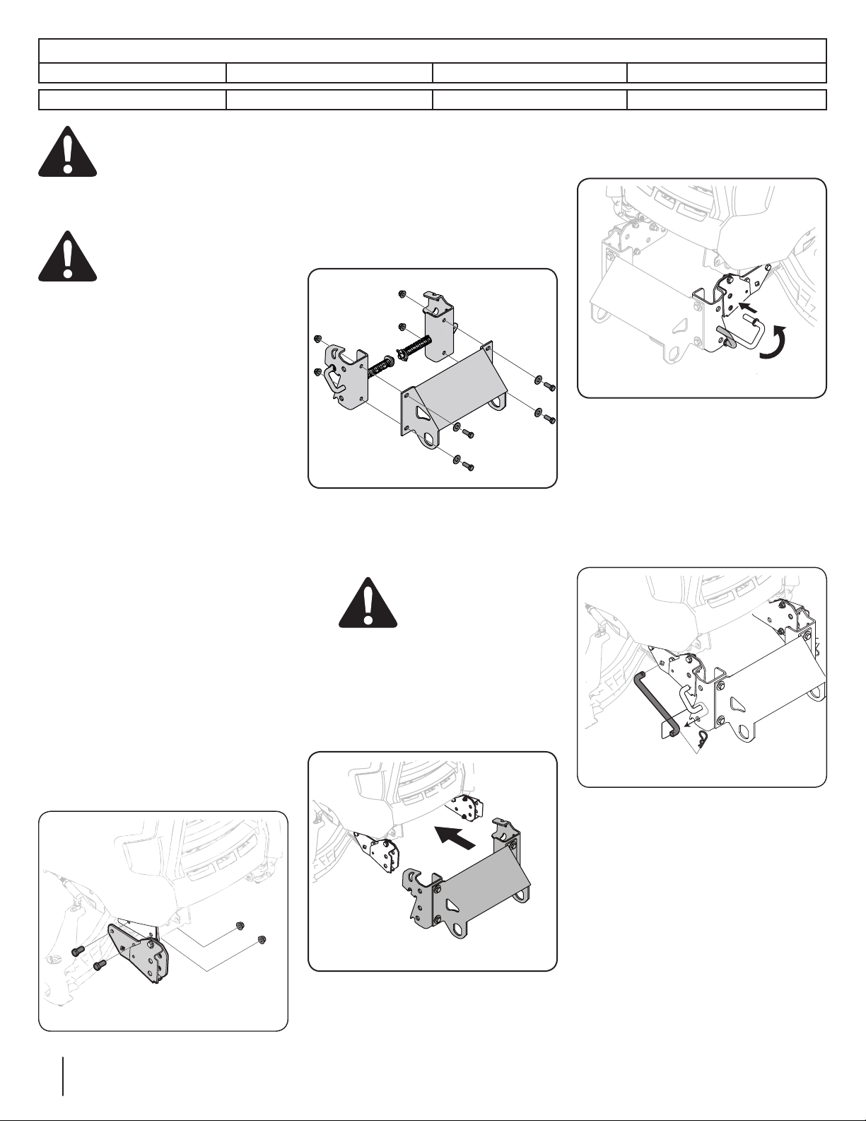
Large Mounting Bracket Assembly
1. Attach RH and LH mounting assemblies
(689-00682) (689-00681) to large
mounting bracket (789-00463) with
4 screws (710-0514) 4 washers (736-
04183) and 4 nuts (712-04065) found in
hardware pack 2 (689-00678). See Figure
2-2.
Figure 2-2
Install Large Mounting Bracket To
Tractor
WARNING! The exhaust
system and surrounding
areas are HOT. To avoid
personal injury, allow the
tractor to cool before
beginning any plow
installation or removal
procedures.
1. Slide large mounting bracket into
brackets installed earlier on tractor. See
Figure 2-3.
Figure 2-3
2. Align FastAttach™ tabs and slide in to
secure.
3. Pull spring pins outward on each side
and rotate into place to lock. See Figure
2-4.
Figure 2-4
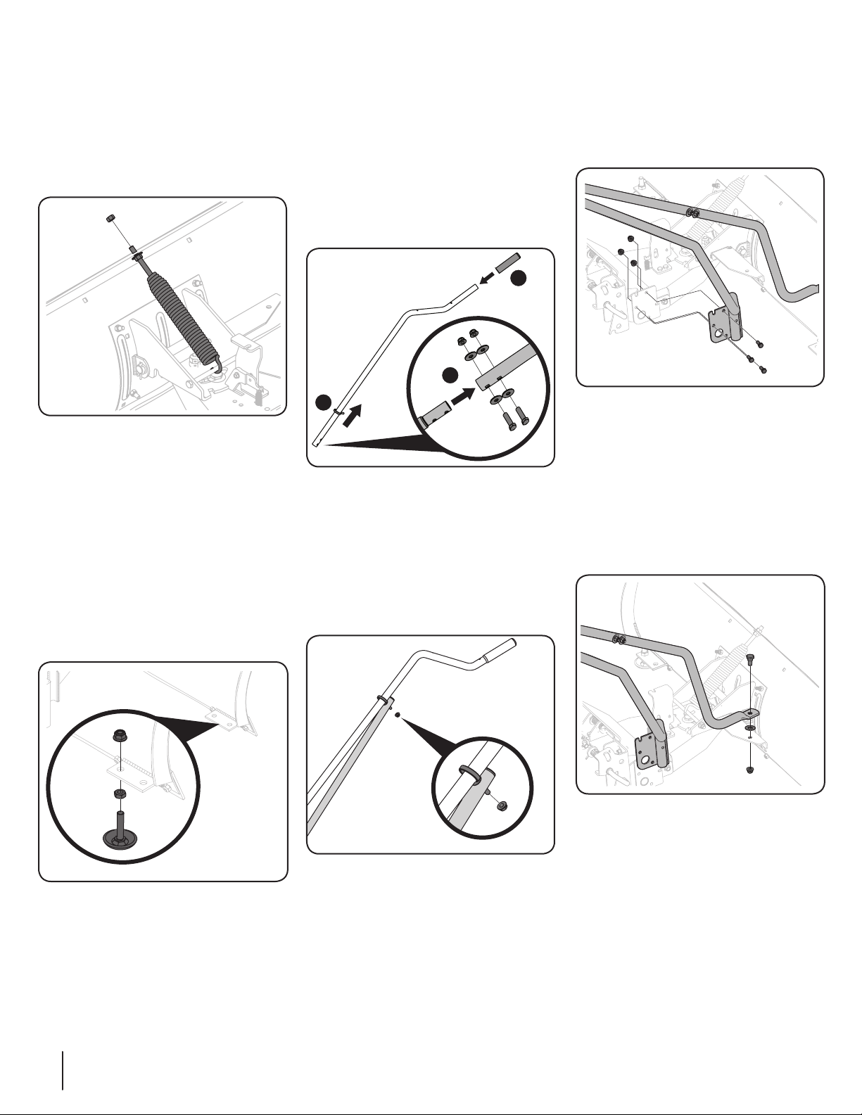
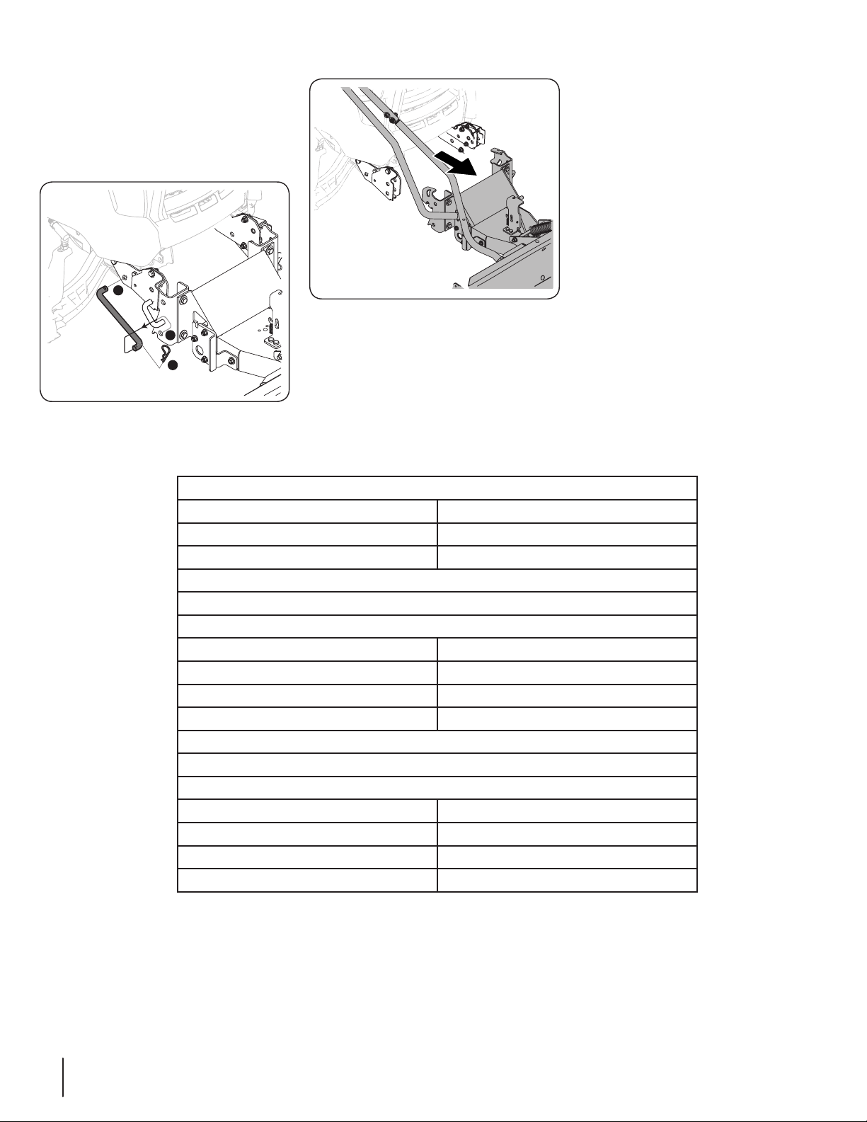
4. Install slotted end of tie rod (747-06957)
into bracket mounted on tractor frame
and then rotate and secure other end of
tie rod into hole and secure with 2 cotter
pins (714-3020) found in hardware pack 2
(689-00678). See Figure 2-5.
5. Repeat with the second tie rod (747-
06957) on the other side.
Figure 2-5
Note: Tighten all hardware that was left
loose in bracket assembly procedure.