Current Tools RotaBoom 77-22 User manual

Current Tools™77 Series Electric Bender – 220 Volt
with Single Shoe Groups
for bending 1/2" thru 2" RIGID - EMT - IMC
and 40 mil PVC coated RIGID Conduit
CURRENT TOOLS • P. O. BOX 17026 GREENVILLE, SC 29606
800.230.5421 or 864.721.4230 • FAX 864.721.4232
www.currenttools.com
Operating, Maintenance, Safety
and Parts Manual
06/17
This manual is free of charge. All personnel who operate this Bender
should have a copy of this manual and read and understand its
contents. To request a copy, call or write to the address below.
Read and understand this material before
operating or servicing this Bender. Failure to
understand how to safely operate and service
this unit may result in serious injury or death.
140
130
50

2
TABLE OF CONTENTS
Safety Alerts ....................................................................................3
Important Safety Information ....................................................4, 5
Specifications – 77 Series Electric Bender – 220 Volt................. 6
Model Descriptions ........................................................................ 6
Features........................................................................................6, 7
Shoe Groups ................................................................................... 8
Conduit Centerline Bending Radii ................................................ 8
Grounding Instructions.................................................................. 9
Mounting Bending Shoes.............................................................10
Mounting Roller Supports............................................................11
General Bending Instructions ................................................12, 13
Bending Instructions for
1 1⁄2" and 2" EMT & IMC Conduit......................................... 14-16
Squeeze Adjustment Procedure for
1 1⁄2" and 2" EMT & IMC Roller Supports..................................17
Maintenance ............................................................................18, 19
Stub-Up Bending Information and Charts............................20, 21
Offset Bending Information and Charts................................22, 23
Troubleshooting ........................................................................... 24
Exploded Views.......................................................................25, 26
Parts List ..................................................................................27, 28
Electrical System Diagram ...........................................................29
Parts List – Bending Shoes & Roller Supports .................... 30-35

Hazards or unsafe
p
ractices which, if not avoided, COULD result in serious
personal in
j
ur
y
or death
.
W
ARNIN
G
Hazards or unsafe
p
ractices which, if not avoided, COULD result in minor
personal in
j
ur
y
or propert
y
damage
.
CA
UTI
ON
Immediate hazards which, if not avoided, WILL result in serious
p
ersonal
in
j
ur
y
or death
.
DAN
G
E
R
THIS SAFETY SYMBOL is used to call your attention to instructions
that concern your personal safety. It means: ATTENTION! BE AWARE!
THIS IS AN IMPORTANT SAFETY INSTRUCTION!
Read, understand, and follow these safety instructions. Failure to follow
these safety instructions may result in injury or death.
Safety Alert
Symbol
SAFETY ALERTS
3

NEVER operate the bender in an explosive atmosphere.
NEVER operate the bender in wet or damp locations.
DO NOT expose the bender to rain.
ALWAYS connect to a power supply that is properly installed and
meets all applicable electrical codes. See grounding instructions
on page 9.
ALWAYS inspect power cord before using bender.
Replace damaged or worn cords.
DO NOT modify the plug provided with the bender.
ALWAYS disconnect power to the bender before servicing.
ALWAYS make sure the circuit breaker switch is in the OFF
position before plugging in. This will reduce the risk of
unintentional starting.
ALWAYS use three-wire, 12 AWG extension cords that have
three-prong grounding type plugs and three hole receptacles
that accept the bender's plug.
NEVER use an extension cord longer than 100 feet.
ALWAYS replace damaged extension cords.
ALWAYS disconnect power to the bender before servicing or
changing shoes, attachments or roller supports, and when not in
use.
ALWAYS inspect the bender before operating. Replace any
damaged, missing or worn parts.
NEVER alter this equipment. Doing so will void the warranty.
NEVER remove guards, they are installed for your protection.
ALWAYS check for damaged or worn parts. Check for alignment
of moving parts, binding of moving parts, breakage of parts,
mounting and any other conditions that may affect its
operation. A guard or other part that is damaged should be
properly repaired or replaced.
RETAIN SAFETY INFORMATION
4
4
IMPORTANT SAFETY INFORMATION
This manual should be read and understood by all personnel who operate
or service this bender. Failure to understand how to safely operate and
service this unit could result in injury or death. This unit should only be
operated and serviced by qualified personnel.
WARNING
DANGER
CAUTION
WARNING
DANGER
CAUTION
WARNING
DANGER
CAUTION
WARNING
DANGER
CAUTION
WARNING
DANGER
CAUTION
WARNING
DANGER
CAUTION
WARNING
DANGER
CAUTION
WARNING
DANGER
CAUTION
WARNING
DANGER
CAUTION
WARNING
DANGER
CAUTION
WARNING
DANGER
CAUTION
WARNING
DANGER
CAUTION
WARNING
DANGER
CAUTION
WARNING
DANGER
CAUTION
WARNING
DANGER
CAUTION

ALWAYS use recommended accessories. Consult this manual for
recommended accessories. The use of improper accessories may
cause risk of injury.
ALWAYS keep hands and feet away from pinch points such as
bending shoes, roller supports and conduit when bender is in use.
Operator must ALWAYS face the front of the bender with the
bending degree scale visible and maintain a minimum of 3 feet
distance from the bender while the conduit is being bent. All
other personnel must remain out of the area while the bender is
in operation.
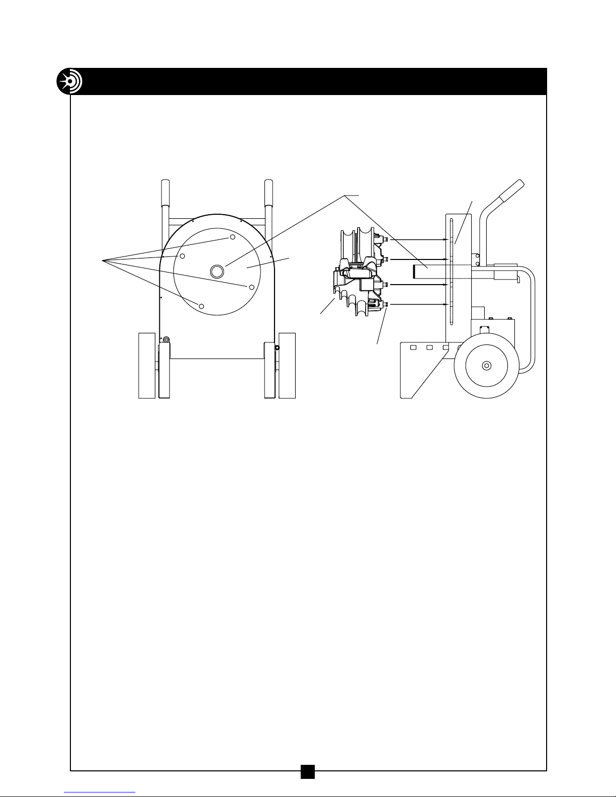
ALWAYS use appropriate shoe groove and roller support for
the type and size conduit to be bent.
If bending shoe will not turn, STOP unit and unplug before
checking for any obstructions.
DO NOT use bender or attachments to do a job for which
it was not designed.
ALWAYS keep conduit under control when unloading.
ALWAYS keep the path of the bending conduit clear of
obstructions. Make sure all obstacles are clear of the bending
path BEFORE you bend the conduit.
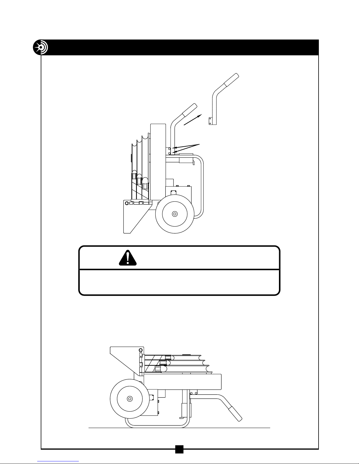
Be sure handle is bolted securely to the bender frame before
moving or lifting the bender.
NEVER stand on bender. Serious injury could occur if the bender
is tipped or if the bending shoe is unintentionally contacted.
ALWAYS wear approved safety glasses when the bender is
in operation.
ALWAYS wear proper apparel. Do not wear loose clothing,
gloves, neckties, rings, bracelets, or other jewelry which may
get caught in moving parts. Non-slip footwear is recommended.
Wear protective hair covering to contain long hair.
ALWAYS keep children away. All visitors should be kept a safe
distance from work area.
ALWAYS make bender childproof with lockouts, master switches
or by unplugging unit.
The bender and some accessories exceed 50 lbs. and will
require more than one person to lift, transport and assemble.
Only use the bender for its intended purpose as specified
in this manual.
ALWAYS use this bender in a dry, well lighted area.
ALWAYS maintain bender with care. Keep bender clean for
best and safest performance.
5
IMPORTANT SAFETY INFORMATION — continued
WARNING
DANGER
CAUTION
WARNING
DANGER
CAUTION
WARNING
DANGER
CAUTION
WARNING
DANGER
CAUTION
WARNING
DANGER
CAUTION
WARNING
DANGER
CAUTION
WARNING
DANGER
CAUTION
WARNING
DANGER
CAUTION
WARNING
DANGER
CAUTION
WARNING
DANGER
CAUTION
WARNING
DANGER
CAUTION
WARNING
DANGER
CAUTION
WARNING
DANGER
CAUTION
WARNING
DANGER
CAUTION
WARNING
DANGER
CAUTION
WARNING
DANGER
CAUTION
WARNING
DANGER
CAUTION
WARNING
DANGER
CAUTION

SPECIFICATIONS – 77 SERIES ELECTRIC BENDER
1/2" thru 2" RIGID conduit
1/2" thru 2" EMT conduit
1/2" thru 2" IMC conduit
1/2" thru 2" 40 mil PVC coated RIGID conduit
1/2" thru 2" schedule 40 steel pipe
The 77 Series Electric Bender is NOT to be
used for bending any conduit or pipe wall thickness above schedule 40 pipe.
width 29 1/2"
length 24 3/4"
height 39"
weight 256 lbs. Power Unit Only - without shoes and roller supports
6
No modification to the
77-22 POWER UNIT is required
to accommodate these shoes
or roller supports.
No tools are required to
install or remove these
shoes and roller supports.
MODEL DESCRIPTIONS
Bender Power Unit and Bender Power Unit with Shoe Group
77-22 Electric Bender Power Unit only, without shoes and roller supports
77SR-22 Electric Bender with shoe and roller support for 1/2" thru 2" RIGID conduit
and schedule 40 pipe and 1/2" thru 1 1/4" IMC conduit
77SE-22 Electric Bender with shoe and roller support for 1/2" thru 2" EMT conduit
Shoe Group ONLY for use with 77-22 Power Unit
700SI 1/2" thru 2" IMC single shoe group for 77-22 power unit
700SP 1/2" thru 2" 40 MIL PVC Coated RIGID single shoe group for 77-22 power unit
FEATURES
1. Bending Degree Scale - easy to read for exact bends.
2. Roller Supports - for supporting the conduit during bending.
3. Hinge Pin - for securing the roller supports.
4. 12 inch Wheels - for easy mobility.
5. D.C. Motor - quiet and strong.
6. Bending Instructions Decal -
easy to read for quick reference.
7. Remote Pendant - with 6 foot cord.
( Bend and unload from pendant. )
8. Removable Handle - may be
removed for dog-leg bends
9. Back Rails - Protect the back
of bender and enable the
bender to be used horizontally
SPECIFICATIONS - 77 SERIES ELECTRIC BENDER WITH SINGLE SHOE GROUPS
140
130
50
40
140
130
50
8
9
5
6
7
4
3
2
1

FEATURES — continued
Special Features
The 77 Series Electric Benders have a unique
feature to remove the handles during a
“Dog-Leg Bend." See Figure 7a below.
The 77 Series Electric Benders may also be used in a horizontal position
The bender can operate in this position as efficiently as it does in the upright
position. See Figure 7b below.
7
Figure 7b
When replacin
g
handle, be sure to replace screws and nuts and also to ti
g
hten
securel
y
before moving or transporting
.
W
ARNIN
G
REMOVE BOTH SCREWS
AND NUTS ON EACH SIDE
TO REMOVE HANDLE
Figure 7a

8
PVC COATED RIGID
700SP - for bending 1/2" thru 2" 40 mil PVC coated RIGID
includes the following items.
Key Catalog Description
1 2-3200 1/2" thru 2" bending shoe
2 2-4300 1/2" thru 2" roller support
3 8-0501 storage box (not shown)
1
RIGID
700SR - for bending 1/2" thru 2" RIGID conduit, 1/2" thru
1 1/4" IMC conduit and 1/2" thru 2" schedule 40 pipe
includes the following items.
Key Catalog# Description
1 2-3000 1/2" thru 2" bending shoe
2 2-4000 1/2" thru 2" roller support
3 8-0501 Storage box (not shown)
1
2
EMT
700SE - for bending 1/2" thru 2" EMT ( Thinwall )
includes the following items.
Key Catalog# Description
1 2-3100 1/2" thru 2" bending shoe
2 2-4200 1/2" thru 2" roller support
3 8-0501 storage box (not shown)
1
2
CONDUIT CENTERLINE BENDING RADII
size 1/2" 3/4" 1" 1 1/4" 1 1/2" 2"
EMT 4-5/16 5-1/2 78-13/16 8-3/8 9-1/4
IMC 4-1/4 5-7/16 6-15/16 8-3/4 8-1/4 9
RIGID 4-1/4 5-7/16 6-15/16 8-3/4 8-1/4 9
PVC COATED RIGID 4-1/4 5-7/16 6-15/16 8-3/4 8-1/4 9
SINGLE SHOE GROUPS
1
2
IMC
700SI - for bending 1/2" thru 2" IMC conduit
includes the following items.
Key Catalog# Description
1 2-3000 1/2" thru 2" bending shoe
2 2-4100 1/2" thru 2" roller support
3 8-0501 storage box (not shown)
2

9
GROUNDING INSTRUCTIONS
In the event of a malfunction or breakdown, grounding provides a path of least
resistance for electric current to reduce the risk of electric shock. The bender is
equipped with an electric cord having an equipment grounding conductor and a
grounding plug. Only connect the bender to a 15 AMP GFCI protected receptacle
which is properly installed and grounded to meet all applicable electrical codes.
Do NOT use an adapter.
Do NOT modify the plug provided. If it will not fit the receptacle, have the
proper receptacle installed by a qualified electrician.
Improper connection of the equipment grounding conductor can result in risk
of electric shock. The conductor with insulation having an outer surface that is
green with or without yellow stripes is the equipment grounding conductor. If
repair or replacement of the electric cord or plug is necessary, do not connect
the equipment grounding conductor to a live terminal.
Check with a qualified electrician or service personnel if the grounding
instructions are not completely understood, or if in doubt as to whether
the bender is properly grounded.
Use only 3-wire extension cords that have 3-prong grounding plugs and
3-pole receptacles that accept the bender’s plug.
Repair or replace damaged or worn cord immediately.
This bender is intended for use on a circuit that has a receptacle that looks
like the one illustrated in Figure 9a above. The bender has a grounding plug
that looks like the plug illustrated in Figure 9b above.
RECEPTACLE PLUG
NEMA 6-15
ELECTRIC SHOCK HAZARD! Only connect the bender to a 15 AMP GFCI
protected circuit. DO NOT modify the plug which is provided with the unit.
Failure to follow these warnings can result in serious injury or death.
WARNING
Figure 9a Figure 9b

10
Figure 10a Figure 10b
MOUNTING BENDING SHOE
Choose the desired shoe (RIGID, IMC, EMT, or 40 mil PVC coated RIGID) and
slide shoe onto the main drive sprocket shaft. See Figure 10a below.
Note: Rigid and IMC conduit are bent on the same shoe. However, the roller
supports are specific for Rigid or IMC.
Next, align the four drive studs on the back of the shoe with the four drive
holes in the main drive sprocket.
Push the shoe onto the main drive sprocket shaft. See Figure 10b.
MAIN
DRIVE
SPROCKET
DRIVE
HOLES
SPROCKET SHAFT
DRIVE
STUDS
BENDING
SHOE
MAIN
DRIVE
SPROCKET

11
Figure 11a
* Greenlee®555®and 555 Classic®are registered trademarks of Greenlee/Textron.
MOUNTING ROLLER SUPPORT
Choose the correct roller support for the
corresponding shoe and type conduit ( RIGID,
IMC, EMT, or 40 mil PVC coated RIGID ). The
appropriate size and type
of roller support MUST be used with the
corresponding shoe size and type.
Mount the roller support on the bender.
Secure the roller support with the quick
release hinge pin. See Figures 11a and 11b.
MOUNTING INSTRUCTIONS FOR
GREENLEE®SHOES AND ATTACHMENTS
Most bending shoes and attachments for the Greenlee®555®and 555 Classic®will
fit the Model #77-22 Bender. In addition, most bending shoes and attachments for
the Model #77-22 Bender will fit the Greenlee®555®and 555 Classic®bender.
Contact Current Tools for specific applications and compatibility.
Figure 11b
Bender shown with
1/2" to 2" EMT roller support
Bender shown with
1/2" to 2" Rigid roller support

12
Figure 12
GENERAL BENDING INSTRUCTIONS
Bending instructions for:
1/2" thru 2" RIGID conduit
1/2" thru 1 1/4" EMT conduit
1/2" thru 1 1/4" IMC conduit
1/2" thru 2" 40 mil PVC coated RIGID conduit
1/2" thru 2" schedule 40 pipe
See pages 10 and 11 for mounting shoe and roller support.
Be sure to match the appropriate shoe with its corresponding roller support.
1. Mark pipe/conduit to the desired length. Note that a 2" minimum distance
from the end of the conduit to the bending mark is required to eliminate
flattening the end of the pipe/conduit. See Figure 12.
NOTE: Stub-up and Offset dimensions can be found on the bending charts
on pages 20 thru 23 of this manual or on the bending instruction decal on
top of each bender.
2. Rotate the bending shoe to 10 degrees below the 0 ( zero ) degree setting,
as shown in Figure 12 below.
DAN
G
ER
NEVER
operate this bender in an explosive atmosphere. In
j
ur
y
or Death ma
y
occur.
2"
MINIMUM
BENDING
MARK
HOOK
2"
MINIMUM
BENDING
MARK
HOOK
0°
-10°

GENERAL BENDING INSTRUCTIONS — continued
13
3. After marking the pipe/conduit, place it into the bender. See Figure 12.
The pipe/conduit should slide over the correct size roller support, through
the shoe groove and into the hook. The bending mark should be at the
front ( OUTSIDE ) edge of the hook. See Figure 12.
4. Using the remote pendant, place the “Bend/Unload" switch in the “bend"
position. Press the “Jog" button and advance the bender shoe. Be sure to
check the alignment of the bending mark as the rotating shoe locks the
pipe/conduit into position. Advance the bender shoe to the desired degree
of bend. When the arrow on the shoe reaches the desired degree of bend,
release the “Jog" button and the bender will stop.
NOTE: Due to springback in pipe/conduit, some over bending is
necessary to achieve the desired degree of bend. See page 21 or
the bending instruction decal on top of each bender for approximate
springback compensation figures.
5. To release the pipe/conduit, place the “Bend/Unload" switch in the
“Unload" position. Press the “Jog" button and reverse the shoe far
enough to release the conduit. Then, rotate the roller support out of
the way. See Figure 13a & 13b. The pipe/conduit can now be removed.
The pipe/conduit should be under control when unloadin
g
.
Failure to do this ma
y
result in in
j
ur
y
or death
.
W
ARNIN
G
Figure 13a
Bender shown with
1/2" to 2" Rigid roller support
Figure 13b
Bender shown with
1/2" to 2" EMT roller support

14
Figure 14a Figure 14b
Figure 14c
BENDING INSTRUCTIONS FOR
1 1/2" AND 2" EMT & IMC CONDUIT
1. See pages 10 and 11 for mounting shoe and roller support.
Be sure to match the appropriate shoe with its corresponding roller support.
NOTE: The frame color of the EMT roller support is silver (see Figure 14a).
The frame color of the IMC roller support is yellow (see Figure 14b).
2. Mark pipe/conduit to the desired length. Note that a 2" minimum distance
from the end of the conduit to the bending mark is required to eliminate
flattening the end of the pipe/conduit. See Figure 14c.
NOTE: Stub-up and Offset dimensions can be found on the bending
charts on pages 20 thru 23 of this manual or on the bending instruction
decal located on the top of each bender.
2"
MINIMUM
BENDING
MARK
HOOK
SILVER YELLOW
EMT ROLLER SUPPORT IMC ROLLER SUPPORT
2"
MINIMUM
BENDING
MARK
HOOK
SILVER YELLOW
EMT ROLLER SUPPORT IMC ROLLER SUPPORT

15
3. Rotate the bending shoe to 10 degrees below the 0 (zero) degree setting.
See Figure 12.
4. After marking the pipe/conduit, place it into the bender. The pipe/conduit
should slide over the roller support and through the shoe groove and into
the hook. The bending mark should be at the front ( OUTSIDE ) edge of
the hook. See Figure 14c.
NOTE: The appropriate size and type of roller support MUST be used
with the corresponding shoe size and type.
5. Step on the “Engaging Pedal" which will raise the rollers to come in
contact with the conduit. See Figure 15. Be sure the correct rollers for
the size conduit being bent are in position to engage the conduit.
NOTE: See SQUEEZE ADJUSTMENT PROCEDURE on page 17.
Figure 15
STOP ROLLERS SHOWN
IN RAISED (BENDING)
POSITION
ENGAGING
PEDAL
BENDING INSTRUCTIONS FOR
1 1/2" AND 2" EMT & IMC CONDUIT — continued

BENDING INSTRUCTIONS FOR
1 1/2" AND 2" EMT & IMC CONDUIT — continued
16
6. Keep foot pressure on the engaging pedal and push the “Bend/Unload”
switch to the “Bend” position. Then press the “Jog” button. The conduit
will pull the roller support against the stop. Foot pressure can then be
removed from the engaging pedal. Be sure to check the alignment of
the bending mark as the rotating shoe locks the conduit into position.
NOTE: If the roller support will not pull against the stop, the squeeze
adjustment is too tight and will need to be adjusted. See squeeze
adjustment procedure on page 17.
Advance the bender shoe to the desired degree of bend. When the pointer
on the shoe reaches the desired degree of bend, release the “Jog” button
and the bender will stop.
NOTE: Due to springback in pipe/conduit, some over bending is necessary
to achieve the desired degree of bend. See page 21 or the bending
instructions decal located on the top of each bender for approximate
springback compensation figures.
NOTE: DO NOT allow the rollers to come in contact with the bending
shoe. The shoe and rollers squeeze the conduit but they should never
touch each other.
7. To release the pipe/conduit, place the “Bend/Unload” switch in the “Unload”
position. Press the “Jog” button and reverse the shoe. The roller support
will then drop, allowing removal of the conduit.
8. After removal of the conduit, inspect it for wrinkling or excessive side marks.
If these conditions occur, refer to the SQUEEZE ADJUSTMENT PROCEDURE.
See page 17.
The pipe/conduit should be under control when unloadin
g
.
Failure to do this ma
y
result in in
j
ur
y
or death
.
W
ARNIN
G

17
Figure 17b
Figure 17a
SQUEEZE ADJUSTMENT PROCEDURE FOR
1 1/2" AND 2" EMT & IMC ROLLER SUPPORTS
The 1 1/2" and 2" rollers on the single shoe EMT Roller Support and the 1 1/2"
and 2" rollers on the single shoe IMC Roller Support on the 77 bender have a
Squeeze Adjustment feature if wrinkling or side marking becomes a problem
during the bending process. This feature allows you to increase or decrease
the amount of pressure applied to the conduit during bending, thereby elimi-
nating these problems. Begin with the 7/8" starting location of the adjusting
bolts as shown in Figure 17a.
1. If wrinkling occurs, pressure against the conduit during the bending process
must increase. To increase the squeeze ( pressure ), loosen both set screws
and turn both adjusting bolts one-half turn clockwise. Bend one piece of
conduit to test the adjustment, and if wrinkling still occurs, repeat the
procedure. Once you have achieved a good bend, tighten both set screws.
NOTE: Both adjusting bolts MUST be in contact with the bender leg.
See Figure 17a.
2. If side marking occurs, pressure against the conduit during the bending
process must be decreased. To decrease the squeeze ( pressure ), loosen
both set screws and turn both adjusting bolts one-half turn counter-clock
wise. Bend one piece of conduit to test the adjustment, if side marking
still occurs, repeat the procedure. Once you have achieved a good bend,
tighten both set screws.
NOTE: Both adjusting bolts MUST be in contact with the bender leg. See
Figure 17a.
STOP
BO
TH ADJUSTING BOLTS
MUST C
ONTACT BENDER LEG
BENDER LEG ADJUSTING BOLT
STARTING LOCATION
OF ADJUSTING BOLT
7/8"
SET SCREW

18
MAINTENANCE
1. The Gear Box is filled with oil at the factory and should not require periodic
flushing. If the Gear Box is opened for repair, flush by filling the unit with
an AGMA #7 oil. Next, run the unit with no load for 3 minutes. Then, drain
and refill the unit with 28 fluid ounces of an AGMA #7 oil such as the ones
listed below.
Amoco – Amoco Worm Gear Oil
Chevron – Cylinder Oil 460X
Exxon – CYLESSTIC TK460
Mobil – 600 W Cylinder Oil
Shell – Sun Gear Oil 7C
2. To inspect FRONT #60 chain tension:
• Remove front cover plate.
• To adjust, loosen hex bolt with 3/4 wrench and rotate chain tensioner
toward chain as shown until chain moves no more than a total of 1/4".
See Figure 18 below.
• Grease chain periodically with a good quality MP grease.
Figure 18
ALWAY
S
disconnect power suppl
y
before removing an
y
guards or covers and
before servicing this bender. Failure to do so ma
y
result in serious in
j
ur
y
or deat
h
.
W
ARNIN
G

19
3. To inspect REAR #40 chain tension:
• Check chain tension after an initial break-in period of 2 - 3 hours of
use and tighten per the instructions below. See Figure 19.
Thereafter, inspect monthly.
• Remove the chain guard by taking out the 2 mounting screws.
• Loosen 8 bolts ( 4 on top and 4 on bottom ) that hold the gear box
in position.
• To tighten chain, move the gear box to the left and re-tighten bolts.
• For correct tension, chain should deflect approximately 1/8".
NOTE: Be sure to keep the gear box and motor in line with the bender.
• Grease chain periodically with a good quality MP grease.
Figure 19
4 BOLTS ON TOP
4 BOLTS ON BOTTOM
CHAIN GUARD
MOUNTING SCREWS
THIS COVER ALLO
WS
ACCESS TO THE
GEARBO
X SPROCKET
IF ADJUSTMENT IS
NEEDED
• Access to the gearbox sprocket
is possible by removing access
door as shown.
MAINTENANCE — continued

20
Figure 20a
Figure 20b
Figure 20c
S
T
UB
LEN
G
T
H
BENDIN
G
MARK
DED
UCT
LEN
G
T
H
S
T
U
B
LEN
G
T
H
S
T
UB
LEN
G
T
H
MARK
PLA
C
E BENDIN
G
MAR
K
IN LINE WITH FR
O
N
T
ED
G
E
O
F
S
H
O
E H
OOK
STUB-UP BENDING INFORMATION AND CHARTS — continued
To locate bending marks and springback of 15, 30, 45, 60, and 90 degree
bends for a desired stub:
1. Check Chart A, B, C or C1 on Page 21 for deduct length. Note that minimum
stub length is deduct length plus 2".
2. Measure and mark desired stub length on conduit ( stub length mark ).
Subtract “Deduct Length" from this mark and make a second mark
( bending mark ). See Fig 20a and 20b. Place bending mark at front edge
of shoe hook. See Figure 20c. Check Chart A, B, C or C1 on Page 21 for
springback of desired degree of bend. Bender should be advanced to this
degree to obtain desired degree of bend.
PLA
CE BENDING MARK
IN LINE
WITH FRONT
EDGE OF SHOE HOOK
This manual suits for next models
4
Table of contents
Other Current Tools Cutter manuals
Popular Cutter manuals by other brands

Textron
Textron Klauke AXELENT EBS6GKSNGBAX manual

Vector Welding
Vector Welding CUT 50PD operating instructions

WOLFF
WOLFF FRASMASTER 230 V Translation of the original instruction

Brother
Brother 891-Z08 Operation manual

Makita
Makita CC300D instruction manual

EIBENSTOCK
EIBENSTOCK ETR 350.1 P Original instructions

Roland
Roland CAMM-1 Pro PNC- 1410 Service notes

EFA
EFA Z28S Operating Instructions, Maintenance instructions, Spare Part List

Gastrodomus
Gastrodomus TA25K Installation, use and maintenance

Baier
Baier BDS 125 N instruction manual

Batavia
Batavia JBJ-XG01-3,6V instruction manual

durher
durher ORDESA M instruction manual