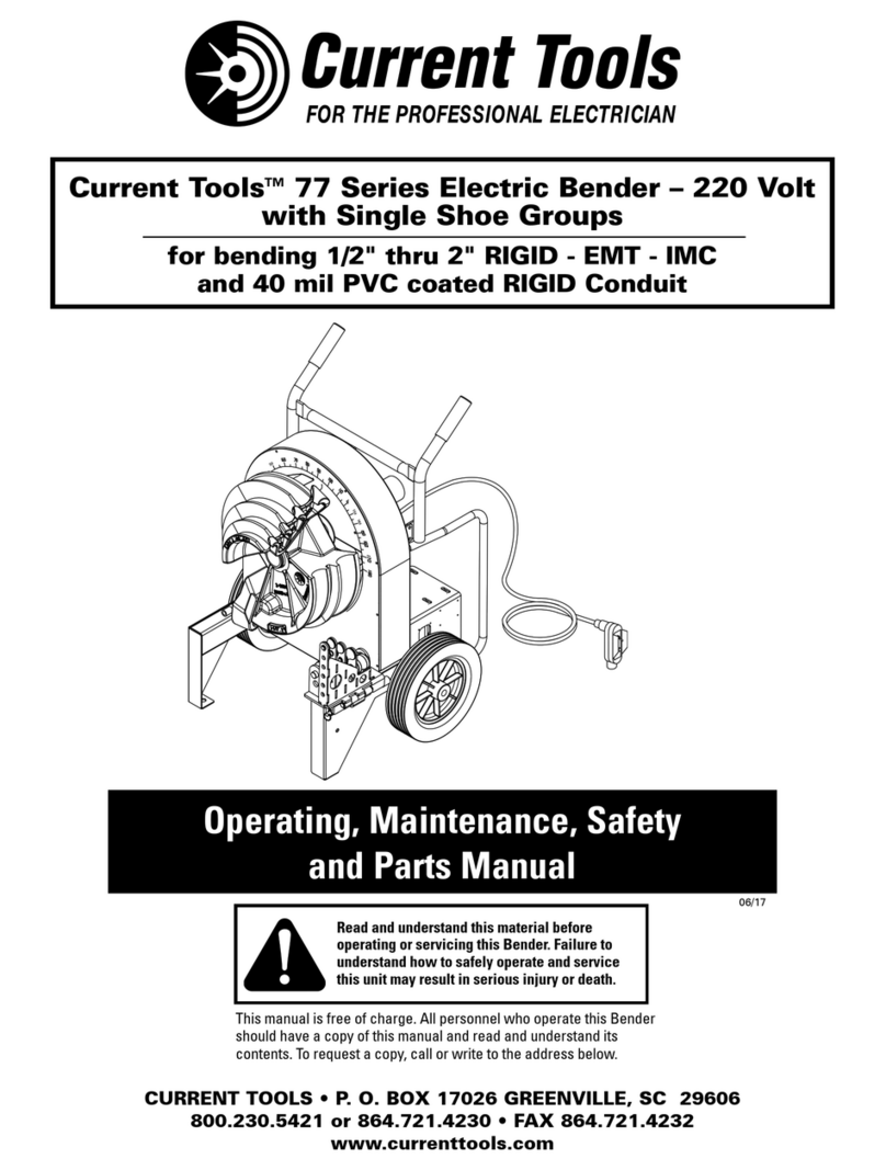
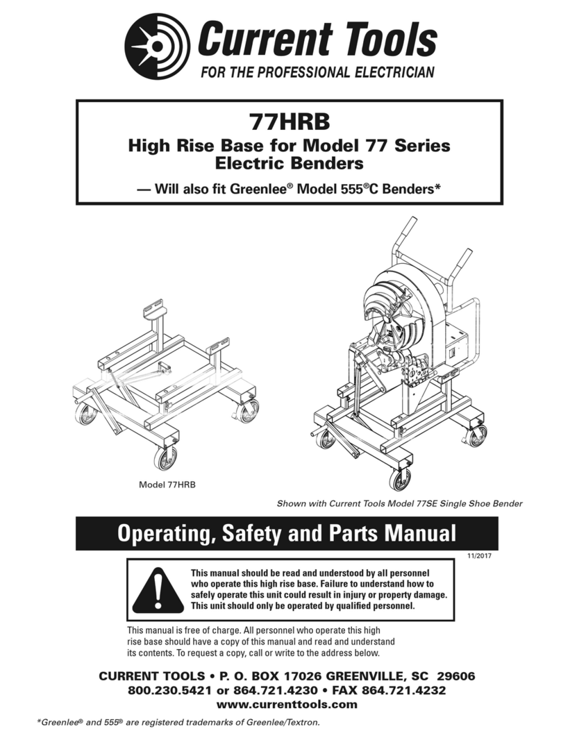
Current Tools Omni 747 User manual

747 Omni™ Bender
CURRENT TOOLS • P. O. BOX 17026 GREENVILLE, SC 29606
800.230.5421 or 864.721.4230 • FAX 864.721.4232
www.currenttools.com
Operating, Maintenance, Safety
and Parts Manual
05/2018
This manual is free of charge. All personnel who operate or
service this Bender should have a copy of this manual and read and
understand its contents. To request a copy, call, write to the address
below or visit our website at www.currenttools.com.
Read and understand this material before
operating or servicing this Bender. Failure to
understand how to safely operate and service
this unit may result in serious injury or death.
CONDUIT BENDER
91FF

2
TABLE OF CONTENTS
Safety Alerts ....................................................................................3
Important Safety Information ....................................................4, 5
Specifications – 747 Omni™Bender .............................................6
Features........................................................................................6, 7
Grounding Instructions...................................................................8
Transporting.....................................................................................9
Set Up.......................................................................................10, 11
Shoe Set-Up.............................................................................12, 13
Bend Angle Limit Switch and Stop Switch..........................14, 15
Support Roller Return Spring ......................................................16
1/2" to 11⁄4" Bending Instructions..........................................17, 18
11⁄2" and 2" Bending Instructions...........................................19, 23
1/2" to 2" Bending Instructions – PVC Coated Rigid...........24, 25
Bend Degree Pointer Adjustment................................................26
Stub Up Bending Information......................................................27
Springback Charts.........................................................................28
Offset Bending Information and Charts................................29, 30
Maintenance ............................................................................ 31-33
Troubleshooting ......................................................................34, 35
Exploded Views and Parts List .............................................. 36-45
Electrical System Diagram ...........................................................46

Hazards or unsafe
p
ractices which, if not avoided, COULD result in serious
personal in
j
ur
y
or death
.
W
ARNIN
G
Hazards or unsafe
p
ractices which, if not avoided, COULD result in minor
personal in
j
ur
y
or propert
y
damage
.
CA
UTI
ON
Immediate hazards which, if not avoided, WILL result in serious
p
ersonal
in
j
ur
y
or death
.
DAN
G
E
R
THIS SAFETY SYMBOL is used to call your attention to instructions
that concern your personal safety. It means: ATTENTION! BE AWARE!
THIS IS AN IMPORTANT SAFETY INSTRUCTION!
Read, understand, and follow these safety instructions. Failure to follow
these safety instructions may result in injury or death.
Safety Alert
Symbol
SAFETY ALERTS
3

RETAIN SAFETY INFORMATION
4
4
IMPORTANT SAFETY INFORMATION
This manual should be read and understood by all personnel who operate
or service this Bender. Failure to understand how to safely operate and
service this unit could result in serious injury or death. This unit should
only be operated and serviced by qualified personnel.
NEVER operate the bender in an explosive atmosphere.
NEVER operate the bender in wet or damp locations.
DO NOT expose the bender to rain.
ALWAYS use 120 VAC, 20 amp ground fault protected
receptacle for power supply that is properly installed and meets
all applicable electrical codes. See grounding instructions on
page 8.
ALWAYS inspect power cord before using bender.
Replace damaged or worn cords. DO NOT modify the plug
provided with the bender.
ALWAYS make sure the circuit breaker switch is in the “off”
position before plugging in. This will reduce the risk of
unintentional starting.
ALWAYS use 12-gauge extension cords that have three prong
grounding type plugs and three-hole receptacles that accept
the bender’s plug. DO NOT use an adapter.
NEVER use an extension cord longer than 100 feet. NEVER
use a damaged extension cord.
ALWAYS disconnect power to the bender before servicing or
changing shoes, attachments or supports, and when not in
use.
NEVER alter this equipment. Doing so will void the warranty
and could cause serious injury or death.
NEVER remove guards, they are installed for your protection.
ALWAYS check for damaged or worn parts. Check for alignment
of moving parts, binding of moving parts, breakage of parts,
mounting and any other conditions that may affect its
operation. A guard or other part that is damaged should be
properly repaired or replaced.
WARNING
DANGER
CAUTION
WARNING
DANGER
CAUTION
WARNING
DANGER
CAUTION
WARNING
DANGER
CAUTION
WARNING
DANGER
CAUTION
WARNING
DANGER
CAUTION
WARNING
DANGER
CAUTION
WARNING
DANGER
CAUTION
WARNING
DANGER
CAUTION
WARNING
DANGER
CAUTION
WARNING
DANGER
CAUTION

ALWAYS keep hands and feet away from pinch points such
as bending shoes, rollers and conduit when bender is in use.
Operator must ALWAYS face the front of the bender with the
bending degree scale visible and maintain a minimum of 3 feet
distance while the conduit is being bent. All other personnel
must remain out of the area while the bender is in operation.
If bending shoe will not turn, STOP unit and unplug before
checking for any obstructions.
DO NOT use bender or attachments to do a job for which
it was not designed.
ALWAYS keep the path of the bending conduit clear of
obstructions. Make sure all obstructions are clear of the bending
path BEFORE you bend the conduit.
NEVER stand on bender. Serious injury could occur if the bender
is tipped or if the bending shoe is unintentionally contacted.
ALWAYS wear approved safety glasses when servicing or
operating this bender.
ALWAYS wear proper apparel. Do not wear loose clothing,
gloves, neckties, rings, bracelets, or other jewelry which may
get caught in moving parts. Non-slip footwear is recommended.
Wear protective hair covering to contain long hair.
ALWAYS use appropriate shoe groove and roller support for
the type and size conduit to be bent.
ALWAYS keep conduit under control when unloading.
Some accessories and components exceed 50 lbs. and will
require more than one person to lift, transport and assemble.
DO NOT bend over 105°. Doing so will cause the hook on the
other side of the shoe to collide with the conduit.
KEEP CHILDREN AWAY. All visitors should be kept at a safe
distance from work area.
MAKE WORKSHOP KID PROOF with padlocks, master switches
or by removing starter keys.
5
IMPORTANT SAFETY INFORMATION continued . . .
WARNING
DANGER
CAUTION
WARNING
DANGER
CAUTION
WARNING
DANGER
CAUTION
WARNING
DANGER
CAUTION
WARNING
DANGER
CAUTION
WARNING
DANGER
CAUTION
WARNING
DANGER
CAUTION
WARNING
DANGER
CAUTION
WARNING
DANGER
CAUTION
WARNING
DANGER
CAUTION
WARNING
DANGER
CAUTION
WARNING
DANGER
CAUTION
WARNING
DANGER
CAUTION
WARNING
DANGER
CAUTION

height 45
1⁄4"
width 32
1⁄2"
length 44"
weight 615 lbs (with shoes)
power
requirement 120 Vac 20 amp GFCI protected circuit
capacity 1⁄2" thru 2" Rigid conduit
1⁄2" thru 2" EMT conduit
1⁄2" thru 2" IMC conduit
1⁄2" thru 2" Rigid aluminum conduit
1⁄2" thru 2" schedule 40 steel pipe
1⁄2" thru 2" 40 mil PVC coated Rigid conduit —
(with optional shoe and roller support)
NOTE: The 747 Omni Bender is NOT to be used for bending any
conduit or steel pipe with wall thickness above schedule 40.
6
FEATURES
• Only two shoes needed to bend 1/2" to 2" Rigid, EMT and IMC conduit.
Optional shoe set bends 1/2" to 2" 40 mil PVC coated Rigid conduit.
• Proven electrical control system.
• Four large casters for ease in moving.
• Remote pendant with magnet.
• Fork pockets for easy lifting.
• Tilts for horizontal bending in a table top position.
• Quick squeeze adjustment for EMT, IMC and Rigid conduit support rollers.
• Adjustable bend angle limit switch for accurate repeat bends.
• Four leveling screws for stability and leveling when bending.
• Lockable storage box for accessories.
• Position locking screw to remove excess play in bender power unit.
SPECIFICATIONS – 747 OMNI BENDER
Bend Radius Chart
Size EMT IMC Rigid PVC Coated Rigid
1/2" 4-5/16" 4-1/4" 4-1/4" 4-1/4"
3/4" 5-1/2" 5-7/16" 5-7/16" 5-7/16"
1" 7" 6-15/16" 6-15/16" 6-15/16"
1 1/4" 8-13/16" 8-3/4" 8-3/4" 8-3/4"
1 1/2" 8-3/8" 8-1/4" 8-1/4" 8-1/4"
2" 9-1/4" 9" 9" 9"

7
FEATURES – CONTINUED
Front View
Rear View
BEND ANGLE
LIMIT SWITCH
RETAINING PAWL
BUILT-IN 1-1/2" & 2"
EMT AND IMC SUPPOR
T
ROLLER ASSEMBLY
SQUEEZE
ADJUSTMENT
HANDLE
SUPPORT
ROLLER
ENGAGEMENT
LEVER
POSITION
L
OCKING
SCREW
POSITIONING
PIN
BENDER
POWER
UNIT
SPARE SHOE
RETAINER
LEVELING
SCREW
(4 PLACES)
SWIVEL
CASTERS
LOCKABLE
STORAGE
BOX
FORK
POCKETS
MOBILE
CARRIAGE

8
GROUNDING INSTRUCTIONS
This bender is intended for use on a circuit that has a receptacle that looks like
the one illustrated below. The bender has a grounding plug that looks like the
plug illustrated below.
In the event of a malfunction or breakdown, grounding provides a path of least
resistance for electric current to reduce the risk of electric shock. The bender is
equipped with an electric cord having an equipment grounding conductor and a
grounding plug. Only connect the bender to a 20 amp GFCI protected receptacle
which is properly installed and grounded to meet all applicable electrical codes.
DO NOT use an adapter.
DO NOT modify the plug provided. If it will not fit the receptacle, have the
proper receptacle installed by a qualified electrician.
Improper connection of the equipment grounding conductor can result in risk
of electric shock. The conductor with insulation having an outer surface that is
green with or without yellow stripes is the equipment grounding conductor. If
repair or replacement of the electric cord or plug is necessary, do not connect
the equipment grounding conductor to a live terminal.
Check with a qualified electrician or service personnel if the grounding
instructions are not completely understood, or if in doubt as to whether
the bender is properly grounded.
Use only 3-wire extension cords that have 3-prong grounding plugs and
3-pole receptacles that accept the bender’s plug.
Repair or replace damaged or worn cord immediately.
P
L
UG
RE
C
EPTA
C
L
E
ELECTRIC SHOCK HAZARD! Only connect the bender to a 20 amp GFCI
protected circuit. Do NOT modify the plug which is provided with the unit.
Failure to follow these warnings can result in serious injury or death.
WARNING

9
TRANSPORTING
To rotate into the horizontal position:
1. Unscrew the position locking screw until it clears the bender power unit.
2. While holding the handle, pull the spring loaded positioning pin. Then use
the handle to rotate the bender power unit into the horizontal position.
3. The spring loaded positioning pin will snap into place when you reach the
horizontal position.
4. To remove excess play, tighten the position locking screw.
ALWAYS rotate the bender power unit into the horizontal position
before lifting, rolling or any type of transporting.
WARNING
Positioning Pin Position
Locking Screw
To lift:
Use the two fork pockets on
either side of the unit to lift
with a forklift.
To roll:
Push and steer the 747 Omni
Bender by using the handle and
the bottom of the roller support
housing.

10
SET UP
Lock the two swivel casters when you reach the desired location.
To stablilize the bender:
Using a 1/2" socket, lower at least two of the leveling screws to hold the
bender in place.
To level the bender (if needed):
Lower the remaining two leveling screws and adjust as required.
The 747 Omni Bender has two bending positions – horizontal and vertical.
If desired, rotate the bender power unit into the vertical position:
1. Unscrew the position locking screw until it clears the bender power unit.

11
SET UP – CONTINUED
2. While holding the handle with
one hand, pull the spring loaded
positioning pin (you may need
to slightly lift up on the handle
to relieve pressure on the
positioning pin).
3. While continuing to hold the
handle, rotate the bender power
unit into the vertical position.
4. The spring loaded positioning
pin will snap into place when you
reach the vertical position.
5. To remove excess play, tighten
the position locking screw.
6. Connect the power cord to a
20 amp, GFCI protected circuit.
7. Place the circuit breaker switch in
the “on” position.

12
SHOE SET-UP
The 747 Omni Bender is equipped with everything needed to bend 1⁄2" thru
2" EMT, IMC, Rigid steel and Rigid aluminum conduit. Also, 40 mil PVC
coated Rigid conduit can be bent with optional shoe and roller support.
1. Choose the shoe for the size conduit you will be bending. The 747 Omni
Bender has a four groove bending shoe for 1⁄2" thru 11⁄4" EMT, IMC and
Rigid conduit. The two groove shoe bends 11⁄2" and 2" EMT, IMC and
Rigid conduit.
If your chosen shoe is not on the front
nose of the bender, you must remove both
shoes and switch their positions.
NOTE: Both shoes are retained by spring
loaded pawls. Press down on the
spring loaded retainer pawls to
remove both shoes (see photo at
right).
2. Place the shoe you are not using onto the
spare shoe tube located on the rear of the bender.
3. Next, you must rotate the bend degree pointer for the size shoe you have
chosen to the minus ten degree (-10˚) position. To do this set the switch
on the pendant to the "UNLOAD" position. Then press the "JOG" button
and rotate the bend degree pointer that matches the size shoe you have
chosen until it is at the minus ten degree (-10˚) position. (See photos
below).
NOTE: Because the pointer will only activate the Bend Angle Limit Switch
and Stop Switch in the clockwise direction, be sure to rotate the
pointer in the counter-clockwise direction when positioning the
pointer.
Pointer set for the 1⁄2"-11⁄4" shoe Pointer set for the 11⁄2"-2" shoe

13
SHOE SET-UP – CONTINUED
The drive sprocket on the 747 Omni Bender has 2 large holes and 2 small
holes to accept the bending shoe drive studs. Therefore, each shoe will
mount in 2 positions. When mounting the shoes, align the large drive
studs with the large holes and the small studs with the small holes. (See
drawing below).
4. Place the shoe on the bender so that the hook for the type conduit to
be bent is at approximately the 6 o'clock position.
Note that the bending shoe hooks are color coded. The blue hooks are
for Rigid and IMC conduit and the silver hooks are for EMT conduit.
NOTE: The bending shoe should be
pushed completely onto the
nose of the bender to allow the
retaining pawl to secure the
bending shoe.
NOTE: Photo shows the 1 1⁄2" to 2"
shoe positioned to bend Rigid
or IMC Conduit.
DRIVE STUDS
BENDING SHOE
(2 LARGE AND 2 SMALL)

14
BEND ANGLE LIMIT SWITCH AND STOP SWITCH
Bend Angle
Limit Switch
The 747 Omni®Bender has an adjustable bend angle limit switch for easy
repeat bends. The bend angle limit switch will adjust from approximately
five degrees (5°) to one hundred and five degrees (105°).
1. To set the Bend Angle Limit Switch, slide to the desired degree of bend.
(See photo below).
NOTE: The pointers will only activate the bend angle limit switch when
operating in the clockwise (bending) direction.
DO NOT bend over 105°. Doing so will cause the hook on
the other side of the shoe to collide with the conduit.
CAUTION

15
BEND ANGLE LIMIT SWITCH AND STOP SWITCH —CONTINUED
Bend Angle
Limit Switch
2. When the pointer reaches the Bend Angle Limit Switch, the bender
will stop.
3. If you do not want to use the Bend Angle Limit Switch, before
bending, slide it clockwise as far as possible (about 105°).
4. An internal stop switch is provided to help avoid damage to the shoe
hook and roller assembly.
Pointer
NOTE: The stop switch
noted in #4 above is located
behind the face plate and
main sprocket of the bender
and is designed to stop the
bender shoe from turning
if the pointer does not
activate the Bend Angle
Limit Switch, thus avoiding
damage to the shoe hook
and roller assembly.
NOTE: If the stop switch activates and
stops the bending shoe from turning in
the bend direction, change the Bend/
Unload switch to the Unload position and
press jog button to turn the shoe in the
counter-clockwise direction.
NOTE: If the pointer passes the Bend Angle
Limit Switch in the bending direction
and does not stop, see page 26 for
troubleshooting instructions.
BEND ANGLE
LIMIT SWITCH

16
SUPPORT ROLLER RETURN SPRING
In addition to the stop switch that is provided to help avoid damage to the
shoe hook and built-in support roller assembly, the 747 Omni™Bender has
a return spring installed on the built-in support roller assembly (See Figure
A1). The return spring is designed to return the support rollers to the down
position (See Figure A2) after a bend is completed. Returning the support
roller assembly to the down position after a bend will help prevent the bender
shoe hooks from contacting the rollers when the rollers are not in use.
Return Spring
Support roller assembly shown
in raised (bending) position
Support roller assembly
shown in down position
Figure A1 Figure A2

17
1⁄2" TO 11⁄4" BENDING INSTRUCTIONS – EMT, IMC AND RIGID
1. Select and mount the 1⁄2" to 11⁄4" shoe as described in the shoe set-up
section on pages 12 and 13.
2. Next, install the 1⁄2" thru 11⁄4" pin-on roller support (see photo below).
1⁄2" thru 11⁄4" EMT, IMC and
Rigid conduit all use the pin-
on 4 roller support.
(Part #747-972)
Attach the pin-on roller support as shown below:
PIN ON
ROLLER
SUPPORT
PIN

18
1⁄2" TO 11⁄4" BENDING INSTRUCTIONS – EMT, IMC AND RIGID
— CONTINUED
2"
minimum HOOK
BENDING MARK
0°
-10°
PIN ON ROLLER SUPPORT
The conduit should be under control when unloading.
Failure to do so may result in injury or death.
WARNING
3. Next, mark conduit to desired length. Note that a minimum of 2" from the
end of the conduit to the front edge of the hook is required to eliminate
flattening the end of the conduit. See figure below.
NOTE: Stub-up and offset information can be found on pages 27-30 in this
manual or on the bending instruction decal on top of each bender.
4. Rotate the bending shoe so that the bend degree pointer is at the minus
ten degree (-10˚) position as shown in the figure below.
5. Place conduit into the bender. The conduit should slide over the roller
support, through the shoe groove and into the hook. The bending mark
should be at the front (outside) edge of the hook. See figure below.
6. After consulting the springback chart (found on page 28 in this manual or
on the bender instruction decal on the top of each bender), slide the bend
angle limit switch to the desired degree. NOTE: If you do not want to use
the bend angle limit switch, slide it clockwise as far as possible (about
105°). See pages 14 and 15 for bend angle limit switch information.
7. Place the pendant switch in the “BEND” position. Press the “JOG”
button and advance the bender shoe. Be sure to check the alignment of
the bending mark as the rotating shoe locks the conduit into position.
Advance the bender shoe to desired degree of bend. When the bend
degree pointer reaches the bend angle limit switch, the bender will stop.
8. To release the conduit, place the pendant switch in the “UNLOAD”
position. Press the “JOG” button and reverse the shoe far enough to
release the conduit. The conduit can now be removed.

19
1½" AND 2" BENDING INSTRUCTIONS – EMT, IMC AND RIGID
1. Select and mount the 11⁄2" to 2" shoe as described in the shoe set-up
section on pages 12 and 13.
2. Next, install the 11⁄2" and 2" pin-on roller support (see photo below).
Attach the pin-on roller support as shown below:
11⁄2" and 2" EMT and IMC
use the pin-on urethane
roller support and the built-in
support roller system.
(Part #747-33)
PIN ON
ROLLER
SUPPORT
PIN
PAGE 19

20
1½" AND 2" BENDING INSTRUCTIONS – EMT, IMC AND RIGID
— CONTINUED
3. Rotate the bending shoe so that the bend degree pointer is at the minus
ten degree (-10˚) position as shown in the figure below.
4. Mark conduit to desired length. Note that a minimum of 2" from the
end of the conduit to the front edge of the hook is required to eliminate
flattening the end of the conduit. See figure below.
NOTE: Stub-up and offset information can be found on pages 27-30 in this
manual or on the bending instruction decal on top of each bender.
5. Place conduit into the bender. The conduit should slide over the roller
support, through the shoe groove and into the hook. The bending mark
should be at the front (outside) edge of the hook. See figure below.
6. After consulting the springback chart (found on page 28 in this manual or on
the bender instruction decal on the top of each bender), slide the bend angle
limit switch to the desired degree. See pages 14 and 15 for instructions on
the Bend Angle Limit Switch.
0°
-10°
BENDING
MARK
2"
minimum HOOK
PIN ON
ROLLER
SUPPORT
Table of contents
Other Current Tools Cutter manuals
Popular Cutter manuals by other brands

Manosplint
Manosplint M40SAB66M User instructions

Battipav
Battipav LEGGERA 49 operating instructions

Guhring
Guhring PF3000 Assembly and Setting Instructions

BN Products
BN Products DC Series Instructions & Parts Lists

Making Memories
Making Memories Slice manual

Textron
Textron Klauke mini ES20 instruction manual