IMPORTANT SAFETY INFORMATION continued
5
ONLY use 3⁄4" or larger double-braided composite pulling rope,
or a pulling rope with a average breaking strength of 26,000 lbs.
NEVER allow the rope to slip on a rotating capstan for more
than a couple of seconds. The rope will wear in that spot and
the rope could break under pressure.
Keep all body parts, hair, loose clothing, etc. away from
rotating parts and pinch points. Keep hands away from
capstan.
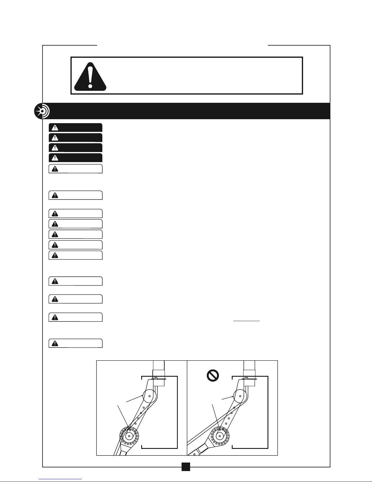
DO NOT allow the rope to overlap on the capstan. If this
condition begins to occur, immediately release the tailing force
on the rope. If this does not remedy the overlap, stop the
puller and run the puller in reverse to unwind the overlap.
During the pull, all personnel must stand to the side of the
cable puller and out of the direct line of tight pulling rope.
The cable puller must be attached to steel conduit or schedule
40 PVC conduit only. When attached to PVC conduit, the
conduit MUST be supported within 2" of the end.
ALWAYS inspect pins to be sure they are fully inserted through
holes and have spring clips properly attached. DO NOT
substitute any other object for factory supplied pins.
When making a vertical cable pull, keep the area underneath
the cable pull clear of all personnel.
Keep fingers away from adjustment holes and pivoting parts.
Fingers can be severed by pivoting parts.
Keep as much rope confined in conduit as possible. This will
help prevent injury should the rope break and whip violently.
DO NOT alter this cable puller. Doing so will void the warranty.
Guards and safety features are provided for your protection.
Wear eye protection when operating the cable puller.
Inspect all components of the cable puller before beginning
any cable pull. Replace any worn or defective components.
Be careful during assembly and disassembly of the cable
puller. Have control of components before removing any pins.
DO NOT use an extension cord longer than 100 ft. Extension
cord should be a minimum of 12 gauge wire with ground.
Some components of the pulling package exceed 50 lbs. and
will require more than on person to lift.
The motor, gear box and capstan may heat up during the pull.
Be careful.
ALWAYS pull in the direction of the arrows on top of the
capstan.
WARNING
WARNING
WARNING
WARNING
WARNING
WARNING
WARNING
WARNING
CAUTION
CAUTION
CAUTION
CAUTION
CAUTION
CAUTION
WARNING
WARNING