Curtis 1YANSAPR Operating instructions

1 of 29
INSTALLATION & OWNER’S MANUAL
Yanmar SA Series
Cab with Heater (p/n: 1YANSAPR)
fits tractor models: SA 221, SA 324, SA 424, SA 325*,
SA 425*. Adaptor kit allows cab to fit with backhoe.
Available Options:
1. Front LED Work Lights (P/N: 9LEDW4)
2. Rear LED Work Lights (P/N: 9LEDW3)
3. Strobe Light (P/N: 9LEDS2)
4. Dome Light (P/N: 9LEDD14)
5. Side View Mirrors (P/N: 9PM5)
6. Rear View Mirror (P/N: 9PM3)
7. Rear Wiper (P/N: 9PWK8512F9-11A)
8. Adaptor kit for Backhoe (P/N: 1YANSAPRBK). Contact Curtis for details.
9. Adaptor kit for Rear Dual SCV’s (P/N: 1YANSARRAK)
(*=Including the heater installation)
Approximate Installation Time *
Experienced Dealer Technician – 4.5 Hours
Average Dealer Technician – 5.5 Hours
Do-It-Yourself – 6.5 Hours
Approximate Product Specifications
Floorboard to Roof Height: 58.25 inches
Weight: 291 lbs.
Cab Width: 51.18 inches
Rev. B, 09/23/2022
P/N: IM-1YANSAPR
The contents of this envelope are the property of the owner. Leave with the owner when installation is complete.
While this cab kit was designed to fit on the vehicle(s) listed above, manufacturing tolerances and vehicle
assembly may affect cab fitment. It is the responsibility of the cab installer to check all vehicle pedals and
levers for full functionality and, as required, adjust the cab fitment to prevent any interference of the cab
components with the travel of pedals or levers.
* Adaptor kit for Rear Dual SCV’s (P/N: 1YANSARRAK) Required

2 of 29
TABLE OF CONTENTS
WARNINGS, TIPS, & REQUIRED TOOLS...................................................... 3
CAB INSTALLATION.................................................................................. 4-21
CAB FEATURES & OPERATION.................................................................. 22
CARE AND MAINTENANCE......................................................................... 23
SERVICE PARTS .................................................................................... 24-26
OPTIONAL ACCESSORIES ......................................................................... 27
TORQUE CHARTS…………………………………………….……………….28-29

3 of 29
Curtis cabs feature an assembly of parts designed for your vehicle which require adjustment
and alignment of components to accommodate vehicle variations and provide proper weather
protection. For accurate installation, proper operation, and years of satisfaction, please read
and understand the installation and owner’s manual fully prior to installing the cab.
From all of us at Curtis, we thank you for choosing our product.
HELPFUL HINTS:
•Refer to parts diagram found in the service parts section of this manual to help identify parts
during the assembly process.
•To assist with the cab installation, leave all fasteners loose for later adjustment unless
otherwise specified.
•Read and understand all instructions before beginning.
•Apply a silicone sealant to seal any minor gaps that may occur due to vehicle variations.
•Use caution to avoid damaging the factory installed threaded inserts or weld nuts. Begin the
thread engagement by hand to avoid or correct potential cross threading.
•Make sure the areas where the supplied self-adhesive hook Velcro and seals will be applied
are clean, dry, and at room temperature for best adhesion.
•Before installing parts with factory installed rubber, make sure the rubber is fully installed
onto the parts for proper fit and sealing.
•Plastic washers have been supplied to provide a weather seal under the heads of some
exterior bolts. The plastic washer should be installed under each bolt head directly
against the outside cab surface. Care should be taken not to over tighten the fasteners
and damage the plastic washer.
driver and passenger.
Curtis accessory weights are listed in product
add additional weight to the base vehicle. All
Curtis Cabs, blades and general accessories
ADDED
WEIGHT
brochures. Deduct the accessory's total weight
from the vehicle's rated capacity and never
exceed the vehicle's rated capacity including
Exposure to Carbon Monoxide
can Cause illness, serious injury or
death. Never operate vehicle if suspicious of Carbon Monox-
ide. Inspect exhaust system for leaks monthly. Leaks can
result from loose connections, corrosion, cracks or other
damage to the exhaust manifold. If leaks are found, repair or
replace exhaust system. Do not use vehicle until repair or
replacement is complete.
•Set of Standard and Metric Sockets including deep sockets (3/8”
Drive)
•3/8” Drive Ratchet with extension
•Torque Wrench
•Set of Standard and Metric Open-End Wrenches
•Set of Standard and Metric Allen Wrenches
•#2 and #3 Phillips Head Screwdrivers
•Drill/Driver
•#2 and #3 Phillips Head Bit
•Utility Knife
•Pair of Scissors
•Shears
•Grease
•Silicone Sealant
•Teflon Tape
•Tape Measure
WARNINGS, TIPS, & REQUIRED TOOLS
TOOLS REQUIRED:
GENERAL INFORMATION BEFORE YOU START
Fastener
Plastic
Washer
Cab
Surface
California Health and Safety Proposition 65 Warning: This product may contain chemi-
cals known to the state of California to cause cancer and birth defects or other reproductive harm.

CAB INSTALLATION
4 of 29
STEP 1: (VEHICLE PREP)
1.1 Disconnect the negative battery cable.
1.2 If equipped, remove and set aside the SMV sign.
1.3 Remove and discard the left rear fir tree clip holding
down the floor mat. See Figure 1.3.
1.4 Remove and save all the fir tree clips from the right floor
mat and temporarily remove the mat. Punch a 5/8” hole
in the center of the underside-indent in the mat in the
location shown. See Figure 1.4.
1.5 Remove and discard the M8 bolt in location shown in
Figure 1.4.
1.6 Re-install the right side floor mat using the fir tree clips
removed earlier.
1.7 Install the supplied aluminum spacer in the hole in the
right side floor mat. See Figure 1.7.
1.8 Loosen the nuts on the rear flashers and slide them out
of the brackets. Keeping the wires attached, let the
flashers rest on the rear fenders out of the way. See
Figure 1.8.
1.9 If installed, remove left side step and save all hardware
for re-installation later. See Figure 1.9.
1.10 If a rear SCV is installed, disconnect the hoses from the
SCV and remove from the ROPS. Refer to the SCV
installation instructions for installation after the cab is
complete.
Fig. 1.3 (Remove Left Rear Fir Tree Clip)
Fig. 1.4 (Punch Hole in Right Floor Mat)
Fig. 1.7 (Install Spacer)
Remove and
Discard
Punch 5/8”
Hole
Spacer
Remove Bolt
Spacer
Rear Flasher
Fig. 1.8 (Move Rear Flashers)Fig. 1.9 (Remove And Save Step)

CAB INSTALLATION
5 of 29
STEP 3: (REAR LEG AND ROPS
MOUNTS)
3.1 Slide on the lower ROPS clamp (taller one) onto the
ROPS just above the flasher bracket. See Figure 3.1.
3.2 With help, attach the left rear leg assembly to the lower
ROPS clamp as well as adding an upper ROPS clamp.
Leave hardware loose at this time. See Figure 3.2.
Ensure there is a gap between the rear leg and the
fender.
Hardware Used Qty
5/16-18 X 3/4 Hex Head Screw 8
5/16-18 Hex Nut 8
Tools required
1/2” wrench and socket
3.3 Repeat steps 3.1 and 3.2 for right rear leg.
Fig. 3.1 (Slide On Lower ROPS Bracket)
Fig. 3.2 (Install Left Rear Leg)
Fig. 2.1 (Pre-Assemble ROPS Mount to Rear Leg)
STEP 2: (PRE-ASSEMBLE REAR LEG)
2.1 Pre-assemble the left rear leg and a ROPS mount. See
Figure 2.1.
Hardware Used Qty
5/16-18 X 3/4 Hex Head Screw 2
5/16-18 Hex Nut 2
Tools required
1/2” wrench and socket
2.2 Repeat step 2.1 for right rear leg.
Gap
ROPS Mount
Larger ROPS Clamp
Larger
ROPS
Clamp
Smaller
ROPS
Clamp

CAB INSTALLATION
6 of 29
STEP 4: (SIDE FRAMES)
4.1 With assistance, remove the left door from the left side
frame by unlatching at the middle handle and lifting the
door off the hinges. Remove the 2 brass washers from
the side frame and set aside for later use. Position the
left side frame in place and loosely secure to the left
rear leg. See Figure 4.1.
Hardware Used Qty
5/16-18 X 3/4 Hex Head Screw 6
Tools required
1/2” wrench or socket
4.2 Secure the left side frame to the floor pan through the
hole from the fir tree plug removed earlier. See Figure
4.2.
Hardware Used Qty
1/4-20 X 3/4 Button Head Screw 1
1/4-20 Hex Nut 1
Tools required
5/32” Allen Wrench
7/16” wrench or socket
4.3 Repeat step 4.1 for the right side frame.
Hardware Used Qty
5/16-18 X 3/4 Hex Head Screw 6
Tools required
1/2” wrench or socket
4.4 Secure the right side frame to the floor pan through the
floor mat hole punched earlier and the aluminum
spacer. See Figure 4.4.
Hardware Used Qty
M8x1.25 X 35mm Button Head Screw 1
Tools required
5mm Allen Wrench
Fig. 4.1 (Install Left Side Frame)
Fig. 4.2 (Install Left Side Frame)
Fig. 4.4 (Install Right Side Frame)
5/16-18 x 3/4
Screws
1/4-20 X 3/4 Button
Head Screw
1/4-20 Nut
M8x1.25 X 35mm
Button Head Screw

CAB INSTALLATION
7 of 29
STEP 6: (WINDSHIELD SUPPORT)
6.1 With assistance, hold the windshield support in place
and attach with a screw to the front of each side frame.
See Figure 6.1. Do not screw in the top at this point.
Hardware Used Qty
5/16-18 X 3/4 Hex Head Screw 2
Tools required
1/2” wrench or socket
STEP 7: (COWL)
7.1 With assistance, carefully slide the cowl in place and
loosely secure with fasteners. See Figure 7.1.
Hardware Used Qty
5/16-18 X 3/4 Hex Head Screw 14
5/16-18 Hex Nut 8
Tools required
1/2” wrench and socket
Fig. 7.1 (Install Cowl)
Fig. 6.1 (Install Windshield Support)
STEP 5: (REAR FLASHERS)
5.1 Attach a flasher relocation bracket to the flasher
mounting tab on the ROPS. See Figure 5.1.
Hardware Used Qty
1/2-13 X 1 Hex Head Screw 1
1/2-13 Hex Nut 1
Tools required
3/4” wrench or socket
5.2 Slide the flasher into the slot in the flasher relocation
bracket and tighten the nut. See Figure 5.1.
5.3 Repeat steps 5.1 and 5.2 for the right rear flasher.
Fig. 5.1 (Install Rear Flashers)
5/16-18 x 3/4 Screws
5/16-18 x 3/4 Screw
5/16-18
Nut

CAB INSTALLATION
8 of 29
STEP 8: (WINDSHIELD)
8.1 Check the windshield support for squareness to the side
frames and tighten the two screws to 12.5 ft.-lbs.
8.2 With assistance, set the windshield up to the side
frames and secure it to the windshield support using the
hinge spacers and hardware. See Figure 8.2. Leave
hardware loose.
Hardware Used Qty
5/16-18 x 1.5” Flat Head Screw 4
5/16-18 Hex Nut 4
Tools required
#3 Phillips screw driver
½” wrench or socket.
8.3 Close the windshield while lifting up on the bottom edge.
Tighten hinge hardware. Caution: The windshield
hinges are plastic components. Do not overtighten
the flat head screws. Torque to 7 ft.-lbs. max.
Tools required
Torque Wrench
8.4 Ensure the windshield latches function properly and the
windshield pivots open.
8.5 Remove the over-tightening caution decal from the top
of the windshield.
Fig. 10.1 (Install Roof)
Fig. 8.2 (Attach Windshield)
Fig. 9.1 (Windshield Wiper Motor)
STEP 10: (ROOF)
NOTE: If installing a Backhoe Compatibility Kit, refer to the
Backhoe Compatibility Kit Installation Instructions for the
roof installation and then proceed to step 11 of these
installation instructions.
10.1 With assistance, set the roof on top of the cab. Loosely
secure with sealing washers on the (8) screws through
the top of the roof. See Figure 10.1.
Hardware Used Qty
5/16-18 x 3/4” Hex Head Screw 8
5/16” Sealing Washer 8
5/16-18 Hex Nut 4
Tools required
1/2” Wrenches and/or Sockets
5/16-18 Flat
Head Screws
5/16-18
Nuts
Hinge Spacer
STEP 9: (WINDSHIELD WIPER
MOTOR)
9.1 Mount the wiper motor to the windshield. See Figure
9.1.
NOTE: Do not install the wiper arm and blade at this time.
Once all the wiring is complete and power is restored, it
can be turned on and off to ensure that the wiper arm
will be parked in the correct position once it is attached
at a later step.
Hex NutPlastic Washer
Rubber Washer
Large Collared
Bushing (inside)
1/4-20 x 5/8” Screw 1/4” Int. Tooth Lock Washer
Small Collared
Bushing (Inside)
Rubber Washer
Steel
Washer
Cap Nut
(8) 5/16-18 x 3/4” Screws
and Sealing Washers
5/16-18 Nuts

CAB INSTALLATION
9 of 29
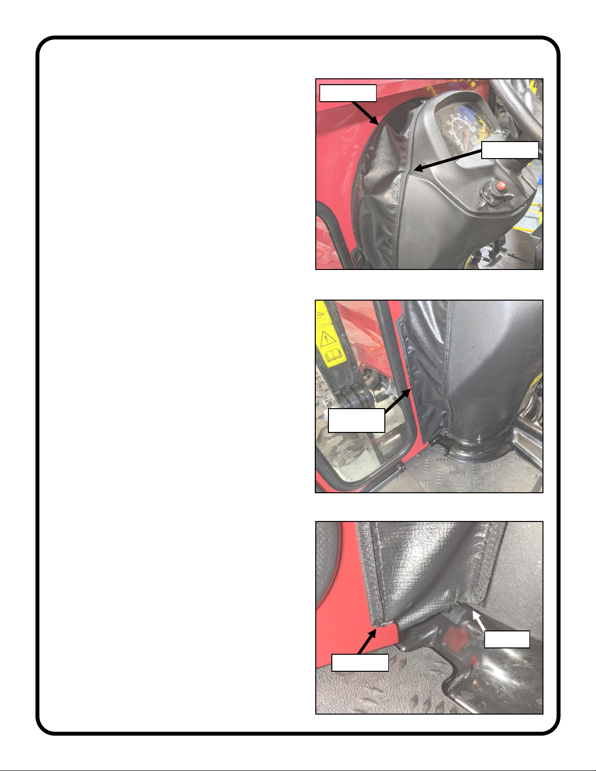
STEP 12: (TIGHTEN HARDWARE)
12.1 Tighten all hardware at this time, using the torque values
given below.
Each side frame can be pushed inward at the back to
close any gaps along the fender contour before
tightening hardware.
For 5/16” bolts that thread into factory installed threaded
inserts in the side frames without plastic washers, use
20 ft.-lbs.
For 5/16” bolts that use plastic washers, use only 12.5 ft.-lbs.
For the remaining 5/16” bolts (the vast majority on the cab)
that thread into hex nuts, use 28 ft.-lbs.
For all other bolt sizes, reference the torque tables at the end
of the manual.
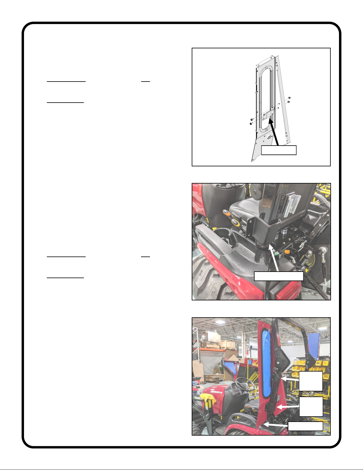
STEP 11: (REAR WINDOW)
11.1 Measure the back of the rear legs, inside to inside, and
adjust the width to 24-7/8”. Measure corner to corner
for squareness, and tighten the (8) sets of screws and
nuts that attach the rear legs to the ROPS, to lock in
this width. See figure 11.1
11.2 Grease the hinge pins for the rear window, and slide on
greased brass washers (one washer per pin). See
Figure 11.2.
11.3 Hang the rear window on the hinges.
11.4 Connect the window latches to the right rear leg by
depressing the tabs on the latch and inserting into the
receivers mounted on the rear leg. Close and check the
alignment of the window. If off, check measurements
and re-align the rear legs. Tighten the hinge hardware
to 7 ft.-lbs. Verify smooth operation of the latches.
Fig. 11.1 (Measure Rear Legs Left to Right)
24-7/8”
STEP 13: (LEFT STEP)
13.1 If equipped, re-install the left step to the new relocation
tabs on the side frame using the hardware saved
earlier. See Figure 13.1
Fig. 13.1 (Install Left Step)
Brass Washers
on Greased Pins
Snap Latches
into Right
Rear Leg
2 Places
Fig. 11.2 (Hang Rear Window)

CAB INSTALLATION
10 of 29
STEP 14: (FRONT FILLERS)
14.1 Pre-install the supplied Velcro to both front fillers. Leave
the release tape on until the filler is in place.
14.2 Set the left/center filler in place over the center console.
See Figure 14.2. The front of the filler should rest on
the arch on the cowl and run tight to the front face. Do
not apply the Velcro at this time. Note the channel in
the console that the filler needs to follow to seal
properly.
14.3 The left side of the filler runs along the left window, then
transitions from inside to outside the cab through the
slot. See Figures 14.3a and b. Do not apply the Velcro
at this time. The inner bottom of the filler should sit just
on top of the vehicle floor pan.
Fig. 14.2 (Set Left/Center Filler Into Place)
Fig. 14.3a (Left Side Of Filler)
Fig. 14.3b (Inside View Of Left Side Transition)
Note Channel
Rest On Arch
Align With
Window
Floor Pan
Transition Slot

CAB INSTALLATION
11 of 29
Fig. 14.4 (Secure Right Side Of Filler)
STEP 14: (FRONT FILLERS CONT’D)
14.4 With the left side located, the right side should end in-
line with the cutout in the cowl. See Figure 14.4. Start
securing the filler in place with Velcro while ensuring the
filler stays in place. Force the filler to follow in and out
of the channel on both sides of the console noted in
Figure 14.2 on the previous page.
14.5 Secure outside of the left side of the filler to the cowl
and floor pan. See Figure 14.5. Ensure there are no
gaps between the filler, the cowl, and the floor pan.
14.6 Slide the Right Side Filler over the brake pedal through
the pedal slit in the bottom and set into place. See
Figure 14.6. Do not secure Velcro at this time.
14.7 Slide the top right edge of the filler through the transition
slot. See Figure 14.6. Secure the top of the filler to the
left/center filler and cowl, then secure sides, followed by
the bottom along the floor pan.
Fig. 14.5 (Outside View Of Left Side Transition)
Fig. 14.6 (Right Side Filler)
Match Edges
Transition Slot
Pedal Slit
Mind Gaps
Transition Slot
Mind Gaps
Mind Gaps

CAB INSTALLATION
12 of 29
STEP 15: (CAB WIRING)
15.1 Attach the main power wire harness to the windshield
wiper connector, and secure to the windshield support
using a P-clip and hardware. Make sure there is
enough slack to fully open the windshield. See Figure
15.1.
Hardware Used Qty
#10-32 x 1/2” Pan Head Screw 1
#10-32 Hex Nut 1
Tools required
#2 Phillips Screw Driver
3/8” Wrench or Socket.
15.2 Run the harness along the windshield support and
down the side frame. Secure it with (2) more P-clips
and hardware. See Figure 15.2. Connect the harness
to the heater switch.
Hardware Used Qty
#10 x 3/4” Self-Drill Screw 2
Tools required
#2 Phillips Screw Driver
15.3 Snap in the heater switch into the rectangular cutout in
the cowl and connect the harness. See Figure 15.3.
Secure harness to side frame just above the cowl using
a P-clip and self-drill screw. Use a cable tie to loosely
secure the harness wires together as shown.
Hardware Used Qty
#10 x 3/4” Self-Drill Screw 1
Tools required
#2 Phillips Screw Driver
15.4 Secure the harness with one more P-clip halfway
between the two P-clips on the side frame.
Hardware Used Qty
#10 x 3/4” Self-Drill Screw 1
Tools required
#2 Phillips Screw Driver
15.5 The rest of the harness runs down the side frame and
through the 1/2” hole in the floorboard. See Figure
15.5. The harness will be secured at a later step along
with the heater hoses.
The rest of the connections will be finished after the
heater installation.
Fig. 15.1 (Attach Main Harness To Wiper Connector)
Fig. 15.3 (Route Harness To Heater Switch)
Secure With
P-Clip
Fig. 15.5 (Harness Runs Down Side Frame)
Fig. 15.2 (Secure Harness With P-Clips)
Secure With
P-Clips
Secure With
P-Clip
Heater
Switch
Cable Tie

CAB INSTALLATION
13 of 29
STEP 16: (PRE-ASSEMBLE HEATER)
16.1 Remove the heater screws shown in Figure 16.1 and
reuse to attach the heater brackets to the sides of the
heater box. Tighten hardware.
Tools required
#2 Phillips Screw driver
16.2 Apply 1/4” wiring loom to the heater wires. See Figure
16.2.
Fig. 16.1 (Pre-Install Heater Brackets)
Fig. 16.2 (Apply Loom to Heater Wires)
Connect and cover
1/4” Loom
Reuse
Screws
Reuse
Screws
STEP 17: (INSTALL HEATER)
17.1 Install the 2 supplied plastic snap bushings in the right
cab floorboard. See Figure 17.1.
17.2 Attach the heater to the cowl. See Figure 17.2.
Hardware Used Qty
1/4-20 x 5/8” Hex Head Screw 4
Tools required
3/8” socket or wrench
Snap Bushings
1/4-20
Screws
1/4-20
Screws
Fig. 17.1 (Install Snap Bushings)
Fig. 17.2 (Install Heater)

CAB INSTALLATION
14 of 29
STEP 17: (INSTALL HEATER CONT’D)
17.3 Connect the heater leads to the wiring harness. See
Figure 17.3.
17.4 Apply the supplied 1/2” wire loom to the heater wires.
See Figure 17.4.
Fig. 17.3 (Connect Heater Leads to Wiring Harness)
Fig. 18.3 (Tee Fitting)
Fig. 17.4 (Apply 1/2” Wire Loom)
Heater Tee
STEP 18: (HEATER PLUMBING)
18.1 Drain coolant (There is a drain hose connected to the
radiator on the right side).
18.2 Confirm the coolant has completely drained from the
other side and reconnect the drain hose. Relocate your
drain pan under the lower radiator hose, loosen the
clamp, and remove the hose from the radiator.
18.3 Cut the lower radiator hose 1.5” above the lower bend.
Then cut an additional inch off of the end still attached
to the engine to make room for the heater tee. See
Figure 18.3.
18.4 Install the supplied tee fitting and one of the large hose
clamps to the bent piece of radiator hose leaving the
clamp loose for now. Install the assembly back onto the
radiator with the original clamp. See Figure 18.3.
18.5 Attach the lower radiator hose to the other side of the
tee fitting with the remaining large hose clamp. Inspect
the lower radiator hose to confirm it is not pushed up
against any sharp edges and further trim to length if
necessary. Orient the Tee fitting per figure 18.3 and
tighten the clamps.
Connect to
harness
Apply Loom
Hose Clamps

CAB INSTALLATION
15 of 29
Fig. 18.7 (Heater Sending Unit Adapter Assembly)
STEP 18: (HEATER PLUMBING
CONT’D)
18.6 Unplug and remove the temperature sending unit from
the thermostat housing.
18.7 Thread in the sending unit adapter using Teflon tape.
Ensure the threaded hole in the middle faces up. See
Figure 18.7.
18.8 Thread the 90° elbow into the middle threaded hole
using Teflon tape. See Figure 18.7.
18.9 Thread the hose nipple into the 90° elbow using Teflon
tape. See Figure 18.7.
18.10 Thread the temperature sending unit into the end of
the sending unit adapter using Teflon tape. See Figure
18.7. Re-connect the sending unit wiring.
18.11 From inside the cab, insert each end of the supplied
heater hose through each bushing in the floorboard and
route them inward toward the brake pedal and up
toward the engine. Use the natural curve of the hose to
take corners and prevent kinking.
18.12 Connect one end of the hose to the hose nipple with a
small hose clamp. See Figure 18.12.
18.13 Connect the other end of the hose to the tee fitting with
a small hose clamp. See Figure 18.13.
Fig. 18.12 (Heater Supply Hose)
Fig. 18.13 (Heater Return Hose to Tee)
Sending Unit
Adapter
90° Elbow Hose Nipple
Sending Unit
Supply Hose
Return Hose

CAB INSTALLATION
16 of 29
Fig. 18.14 (Heater Shut-Off Valve)
STEP 18: (HEATER PLUMBING
CONT’D)
18.14 At installer’s preference, select a location to splice the
supplied shut-off valve into the supply line coming from
the nipple in the sending unit adapter. See Figure
18.14.
18.15 Wrap the hose closest to the vehicle under the floor
pan with the supplied spiral wrap to protect heater hose.
See Figure 18.15.
18.16 Inside the cab, cut the hose to length and connect to
the heater with small hose clamps. See Figure 18.16.
18.17 Use the supplied large P-clip and a self-drill screw to
secure the heater hose and wiring harness to the side
frame. See Figure 18.16. Ensure the hose does not
interfere with brake pedal use.
Tools required
#2 Phillips Screw driver
Fig. 18.15 (Heater Supply Hose)
Fig. 18.16 (Connect Hose to Heater)
Shut-Off Valve
Spiral Wrap
P-Clamp

CAB INSTALLATION
17 of 29
STEP 19: (FINISH WIRING)
19.1 Use a supplied cable tie to secure the wiring harness to
the heater hoses. See Figure 19.1.
19.2 Use two more cable ties to secure the wiring harness to
the heater hoses near the fuel filter as well as to the
battery cables running along the frame. See Figure
19.2.
19.3 Route the wiring harness around the front of the engine
and secure to vehicle wiring with a cable tie. See
Figure 19.3. Ensure the new wire harness will not
contact the engine fan, pulleys, or exhaust.
Fig. 19.1 (Secure Wiring Harness to Heater Hoses)
Fig. 19.2 (Secure Wiring Harness to Heater Hoses)
Fig. 19.3 (Route Wiring Harness In Front of Engine)
Cable Tie
Cable Ties
Cable Tie

CAB INSTALLATION
18 of 29
STEP 20: (WIPER ARM AND BLADE)
20.1 Turn on the wiper motor briefly, then turn back off. This
will make sure the motor shaft is in the correct parked
position.
20.2 Pre-assemble the wiper arm and wiper blade.
20.3 Install the wiper arm onto the wiper motor so that the
wiper is positioned as shown in figure 20.3. Tighten the
set screws.
Tools required
2.5mm Allen Wrench
20.4 Adjust the length of the wiper arm as long as possible
while still clearing the outer cap nut for the windshield
latches. Turn on the wiper to check proper operation
and to make sure the blade does not contact the
windshield hinge at the top.
Fig. 20.3 (Wiper Arm and Blade)
Set Screw
Set Screw
Fig. 19.5 (Connect Harness to Alternator)
Fig. 19.4 (Connect Ground Terminal)
STEP 19: (FINISH WIRING CONT’D)
19.4 Connect the ground terminal to the vehicle bracket
shown in Figure 19.4.
Hardware Used Qty
#10-32 x 1/2” Phillips Screw 1
#10-32 Nut 1
Tools required
#2 Phillips screw driver
3/8” Socket or Wrench
19.5 Connect the supplied fuse harness ring terminal to the
positive post on the back of the alternator. See Figure
19.5. Connect the red wire from the cab power harness
to the other side of the fuse harness. Coil up excess
harness and wire tie in place.
19.6 Refill coolant, connect battery, check system operation.
Ground Terminal
Positive Post

CAB INSTALLATION
19 of 29
STEP 21: (UNDER SEAT FILLER)
NOTE: Open and or remove the glass rear panel for
easier access.
21.1 Pre-install the supplied Velcro to the under seat filler.
Leave the release tape on until the filler is in place.
21.2 Tip the seat forward and set the filler in place starting
with the slits for the control levers on the left side. See
Figure 21.2. Do not stick Velcro yet.
21.3 Fold and tuck the left rear corner under the rear leg.
See Figure 21.3. Align the inner corner and inner edge
to the rear leg and apply the Velcro.
21.4 Pull the left rear flap back and secure to the rear fender.
See Figure 21.4. The flap should run close to the
ROPS and turn inward to create a water channel.
21.5 Repeat steps 21.3 and 21.4 for the right rear corner.
21.6 If the rear panel was removed for easier access, re-
install it at this time. Secure the rear of the filler to the
glass rear panel. See Figures 21.6a and b.
21.7 Finally, ensure full movement of the control levers and
secure the front half of the under seat filler. Do not
cover any decals.
Note: Ensure the transition noted on Figure 21.3 prevents
water intrusion. Adjustment may be necessary to keep
water from running in.
Fig. 21.2 (Set Filler In Place)
Fig. 21.3 (Secure Rear Left Corner)
Fig. 21.4 (Secure Rear Flap)
Fig. 21.6a (Secure Filler to Rear Panel)
Fig. 21.6b (Secure Filler to Rear Panel)
Control Lever Slits
Align Corner
Align Edge
Across to
Side Frame
Ensure No Gap
Water Channel
Note Transition

CAB INSTALLATION
20 of 29
STEP 22: (ACCESSORIES)
22.1 Install any optional accessories at this time.
22.2 Optional Rear Wiper Note:
For easier wiper motor harness disconnection, cut the
main wiring harness connector off a few inches from the
end and create a jumper harness with it using bullet
connectors. Do not cut the connector off the wiper
motor.
Strip all the wires, crimp a male bullet connector onto
the ground (black) wire of the main wire harness and a
female bullet connector on the positive (red) wire.
Reverse the male and female bullet connectors on the
new jumper wire harness so that the male bullet
connector is on the positive (red) wire and the female
bullet connector is on the ground (black) wire.
22.3 If a rear SCV was previously installed, refer to the Rear
SCV Installation Instructions now for re-installation.
Table of contents
Other Curtis Automobile Accessories manuals

Curtis
Curtis Polaris Ranger 1000 Roof Kit Operating instructions

Curtis
Curtis Polaris XP900 Operating instructions

Curtis
Curtis 47587420002 Operating instructions

Curtis
Curtis 47587421001 Operating instructions

Curtis
Curtis 1POLXP1000RP Operating instructions

Curtis
Curtis 1POLXP1000WS Operating instructions

Curtis
Curtis 47587420001 Operating instructions

Curtis
Curtis 47587417001 Operating instructions

Curtis
Curtis 47587418001 Operating instructions

Curtis
Curtis XP 900 Operating instructions