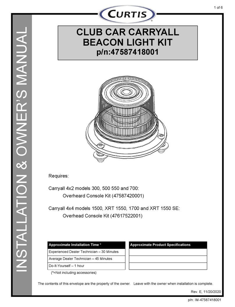
Curtis 47587420001 Operating instructions

1 of 8
INSTALLATION & OWNER’S MANUAL
CLUB CAR CARRYALL
ROPS CAB
OVERHEAD CONSOLE
(w/ Fans)
p/n: 47587420001
(*=Not including accessories)
Approximate Installation Time *
Experienced Dealer Technician – 30 Minutes
Average Dealer Technician – 45 Minutes
Do-It-Yourself – 1 Hour
Rev. F, 11/24/2020
p/n: IM-47587420001
The contents of this envelope are the property of the owner. Leave with the owner when installation is complete.

2 of 8
For accurate installation, proper operation, and years of satisfaction, please read and
understand the installation and owner’s manual fully prior to installing the console.
From all of us at Curtis, we thank you for choosing our product.
WARNINGS, TIPS, & REQUIRED TOOLS
• #1 (small) Phillips screwdriver
• 3/8”, 7/16”, 1/2” open-end wrenches or sockets
• 5/32” and 3/16” Allen wrenches or drivers
TOOLS REQUIRED:

INSTALLATION
3 of 8
Fig. 2.2
Cable Tethers
Fig. 2.3
Yellow/Black
For Strobe Light
Orange/Black
For Dome Light
1. Vehicle Preparation:
1.1 Installation of a Dome Light, Strobe Light, or Rear Work
Light requires the removal of the plastic roof. If installing
any of these accessories, remove the plastic roof as
outlined in the accessory instructions.
Note: If 7.5-amp fuse was installed in vehicle when installing
wiper, switch back to 15-amp fuse.
2. Dome Light and/or Strobe Light pre-
wiring:
(skip to step 3 if not installing either of these)
2.1 Poke up through the headliner with a screwdriver or awl
at each of the 2 smaller holes in the windshield support.
Note: Poke the holes from the headliner side up through the
hole in the roof to avoid having the headliner pull away
from its glued surface.
2.2 Install the end of each Tether from the Console into the
Windshield Support and allow the Console to hang. See
figure 2.2.
Note: If an interior mirror is installed, remove the mirror from
the mounting bracket.
2.3 Cut the cable tie from each of the two coiled wires inside
the console. Be careful to not cut any wires. Feed each
wire through the hole in the roof directly above the
wire. See figure 2.3.
Note: Leave the corresponding wires coiled if not installing a
strobe light or dome light.
• Orange/ black for Dome Light through center right.
• Yellow/black for Strobe Light through center left.

INSTALLATION
4 of 8
2.4 Slide a rubber grommet onto each wire from step
2.3 and install the grommet into the hole in the
roof.
3. Console Wiring:
3.1 Unplug the cab power wire from the wiper motor.
Connect the cab power wire to the short harness
(without wire loom) inside console from the fuse
block. See figure 3.1.
Note: the wire connections from the console fuse block
are polarized to help prevent connecting to the
wrong harness.
3.2 Make sure the other wire (with wire loom) is rout-
ed through the large hole in the center of the con-
sole and connect that to the wiper motor.
3.2 Install and connect all accessories at this time.
4. Install Console Panel:
4.1 Install a 1/4-20 clip nut (4 total) into the slots and
holes at the corner of each flange of the wind-
shield support, with the flat side of the nut on the
outside. See figure 4.1.
NOTE: Ensure that the wiper wire from the console is
routed through the hole in the center of the bottom
face of the console.
4.2 Place the console up against the windshield
support and loosely thread a 1/4-20 x 5/8” bolt into
the clip nuts at each corner.
4.3 Verify that no wires are visible or pinched between
the console and windshield support, and the wiper
wire is not pinched by the interior mirror mount.
4.4 Connect the wiper wire from the console to the
wiper motor.
4.5 Turn the ignition switch on. Verify the function of
each switch and accessory, then turn the ignition
off.
4.6 Tighten the 1/4-20 bolts for the console to 120±5
inch-pounds.
4.7 If you removed the plastic roof to install a Dome
Light, Strobe Light, or Rear Work Lights, re-install
the plastic roof per the instructions included with
those kits.
Fig. 3.1
Connection for
console
Fig. 4.1
Install Clip nuts to
windshield support
as shown

INSTALLATION
5 of 8
5. Changing Fuse (For Gasoline Vehicles
Only):
NOTE: If you have the electric vehicle, skip this
section and proceed to step 6.
5.1 Lift bed or remove seat in order to access
electronic component box.
5.2 Remove the screw that secures the cover to the
electronic component box in the compartment
under the driver’s seat as shown. Retain the
screw and cover for reinstallation. (Figure 5.2).
5.3 Replace the 10 Amp fuse (or 7.5 if cab is installed)
with supplied 15 Amp ATO/ATC fuse. (Figure 5.3)
Reattach the cover onto the electronic component
box. Tighten screw to 17 in./lbs. (1.9 Nm).
6. Changing Fuse (for Electric Vehicles
with cab wiper previously installed):
NOTE: If you have the gasoline vehicle or have not
installed the 7.5 amp fuse for the cab wiper,
disregard this section.
6.1 Locate the fuse block under the front hood.
Remove 7.5 Amp fuse installed for cab with 15
amp fuse supplied with this kit or removed in Cab
installation. (Figure 6.1)
Front of
Carryall
Figure 5.2
Electronic component box
Fig. 5.3
Front of Cab
Replace 10 (or 7.5) Amp
fuse with 15 Amp fuse
Front of
Carryall
Fig. 6.1
Install15 amp
fuse here

6 of 8
OVERHEAD CONSOLE TROUBLESHOOTING
Condition Possible Solution
• All console lights are off • Vehicle Ignition Key is off
• Check 15 Amp fuse
• One switch light is off • Check fuse for that device (see below)
• Switch is not connected to fuse block
• Switch light is on, device does not function • Device is not connected to console
• Connection polarity is reversed
• Check device to 12V power source
• Console will not turn off • Check cab wiring
• Relay harness is not installed
FRONT
LIGHTS:
5 AMP
DOME/
STROBE:
3 AMP
FANS:
5 AMP
WIPER:
7.5 AMP
PASSENGER SIDE
FRONT OF CAB
UNUSED
UNUSED

7 of 8
SERVICE PARTS
#PART NUMBER. DESCRIPTION QTY.
18SV-FP01-B4 FUSE BLOCK, 6-POSITION WITH MOUNTING BRACKET 1
28SV-OHCFC-B4 FUSE COVER 1
39SV-OHC1 AXIAL FAN, 80mm X 80mm 1
49SV-LVR02 LOUVER VENT, 4” LOW-PROFILE 1
59SV-WHOHC1 WIRE HARNESS, FUSE BLOCK 1
69SV-WHOHC2 WIRE HARNESS, WIPER 1
79SV-WH-00030 WIRE HARNESS, BEACON LIGHT AND DOME LIGHT 1
89SV-WH-00031 WIRE HARNESS, WORK LIGHTS 1
99SV-OHCSCC SWITCH SET, (SET OF 3 SWITCHES WITH COVERS) 1
123
4
9
5
6
7
8

8 of 8
GENERAL TORQUE SPECIFICATION TABLE
Use the following torques when special torques are not given. These values apply to fasteners as received from
suppliers, dry, or when lubricated with normal engine oil. They do not apply if special graphited or moly disulphide greases or
other extreme pressure lubricants are used. This applies to both UNF and UNC threads. Remember to always use grade five
or better when replacing bolts.
IMPORTANT: On all PLATED GRADE 8 bolts, reduce torque 15% from listed bolt torque specification.
Size of Screw Property Class
Course Thread Fine Thread
Pitch (mm) Pounds Feet Newton-Meters Pitch (mm) Pounds Feet Newton-Meters
M6
5.6
1.0
3.6-5.8 4.9-7.9
-
- -
8.8 5.8-9.4 7.9-12.7 - -
10.9 7.2-10 9.8-13.6 - -
M8
5.6
1.25
7.2-14 9.8-19
1.0
12-17 16.3-23
8.8 17-22 23-29.8 19-27 25.7-36.6
10.9 20-26 27.1-35.2 22-31 29.8-42
M10
5.6
1.5
20-25 27.1-33.9
1.25
20-29 27.1-39.3
8.8 34-40 46.1-54.2 35-47 47.4-63.7
10.9 38-46 51.5-62.3 40-52 54.2-70.5
M12
5.6
1.75
28-34 37.9-46.1
1.25
31-41 42-55.6
8.8 51-59 69.1-79.9 55-68 75.9-92.1
10.9 57-66 77.2-89.4 62-75 84-101.6
M14
5.6
2.0
49-56 66.4-75.9
1.5
52-64 70.5-86.7
8.8 81-93 109.8-126 90-106 122-143.6
10.9 96-109 130.1-147.7 107-124 145-168
M16
5.6
2.0
67-77 90.8-104.3
1.5
69-83 93.6-112.5
8.8 116-130 157.2-176.2 120-138 162.6-187
10.9 129-145 174.8-196.5 140-158 189.7-214.1
M18
5.6
2.0
88-100 119.2-136
1.5
100-117 136-158.5
8.8 150-168 203.3-227.6 177-199 239.8-269.6
10.9 175-194 237.1-262.9 202-231 273.7-313
M20
5.6
2.5
108-130 146.3-176.2
1.5
132-150 178.9-203.3
8.8 186-205 252-277.8 206-242 279.1-327.9
10.9 213-249 288.6-337.4 246-289 333.3-391.6
METRIC BOLT TORQUE SPECIFICATIONS 5.6 8.8 10.9
SAE Grade No.
Bolt head identification
mark as per grade.
NOTE: Manufacturing
Marks Will Vary
TORQUE TORQUE TORQUE
Bolt Size Pounds Feet Newton-Meters Pounds Feet Newton-Meters Pounds Feet Newton-Meters
Inches Millimeters Min. Max. Min. Max. Min. Max. Min. Max. Min. Max. Min. Max.
1/4 6.35 5678911 12 15 12 15 16 20
5/16 7.94 10 12 14 16 17 20.5 23 28 24 29 33 39
3/8 9.53 20 23 27 31 35 42 48 57 45 54 61 73
7/16 11.11 30 35 41 47 54 64 73 87 70 84 95 114
1/2 12.70 45 52 61 70 80 96 109 130 110 132 149 179
9/16 14.29 65 75 88 102 110 132 149 179 160 192 217 260
5/8 15.88 95 105 129 142 150 180 203 244 220 264 298 358
3/4 19.05 150 185 203 251 270 324 366 439 380 456 515 618
7/8 22.23 160 200 217 271 400 480 542 651 600 720 814 976
125.40 250 300 339 406 580 696 787 944 900 1080 1220 1464
1-1/8 25.58 - - - - 800 880 1085 1193 1280 1440 1736 1953
1-1/4 31.75 - - - - 1120 1240 1519 1681 1820 2000 2468 2712
1-3/8 34.93 - - - - 1460 1680 1980 2278 2380 2720 3227 3688
1-1/2 38.10 - - - - 1940 2200 2631 2983 3160 3560 4285 4827
*Thick Nuts must be used with Grade 8 bolts
58*
2
BOLT TORQUE
BOLT TORQUE SPECIFICATIONS
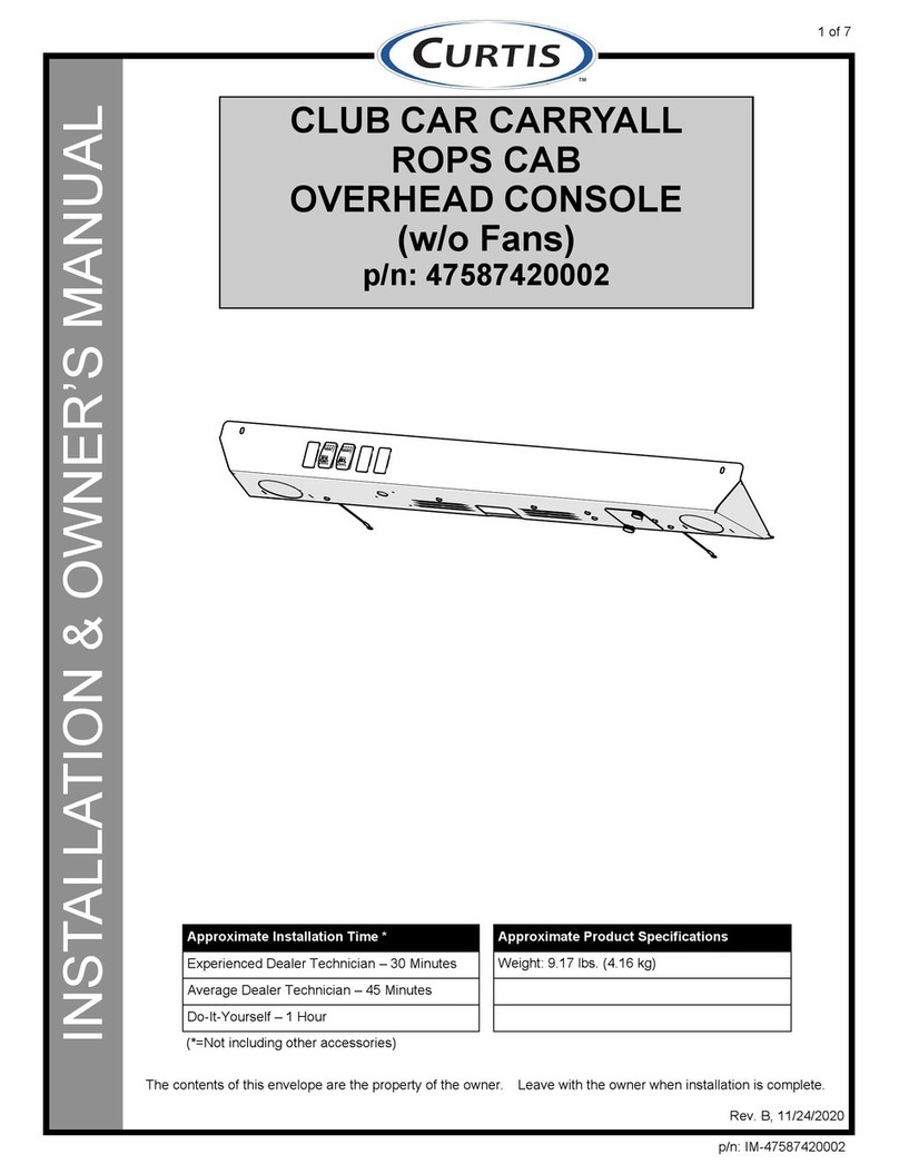
Table of contents
Other Curtis Automobile Accessories manuals

Curtis
Curtis 47587421001 Operating instructions

Curtis
Curtis 1POLXP1000WS Operating instructions

Curtis
Curtis 1YANSAPR Operating instructions

Curtis
Curtis 1POLXP1000RP Operating instructions

Curtis
Curtis 47587418001 Operating instructions

Curtis
Curtis 1POLXP1000GS Operating instructions

Curtis
Curtis XP 900 Operating instructions

Curtis
Curtis 1POLXP1000DR Operating instructions

Curtis
Curtis 1POLXP1000DR Operating instructions

Curtis
Curtis Polaris XP900 Operating instructions