Curtis 1POLXP1000DR Operating instructions

1 of 9
INSTALLATION & OWNER’S MANUAL
Polaris Ranger 1000 Door Kit
Kit p/n:1POLXP1000DR
Fits UTV Models:
POLARIS RANGER 900, XP 900, 1000
& XP 1000
Rev. A, 06/30/2021
p/n: IM-1POLXP1000DR
(*=Not including accessories)
Approximate Installation Time *
Experienced Dealer Technician – 30 minutes
Average Dealer Technician – 45 minutes
Do-It-Yourself – 60 minutes
Approximate Product Specifications
Weight: 56.5 lbs.
Cab Width: 61 inches
The contents of this envelope are the property of the owner. Leave with the owner when installation is complete.
Register your new product quickly online at
Curtiscab.com/product-registration/
Download a digital copy of your installation
instructions online at Curtiscab.com/literature/
Curtis encourages all customers to register their
Curtis products. However, failure to do so will not
diminish right to warranty. Curtis Industries does not
sell or share your information with anyone else.
Curtis strives to continuously improve our products,
technical documentation, etc. Therefore, the
installation manual for this product may have been
updated after your product was packaged. The
latest revision of the installation manual can always
be found at the website above.
Available Options:
1. Roof Kit (P/N: 1POLXP1000RF)
2. Windshield Kit (P/N: 1POLXP1000WS)
3. Rear Panel Kit (P/N: 1POLXP1000RP)
4. Front Wiper Kit (P/N 1POLXP1000WK)
5. Side View Mirrors (P/N: 9PM5)
6. Door Restraint Kit (P/N: 1POLXP1000GS)

2 of 9
Curtis cabs, kits, and accessories feature an assembly of parts designed for your vehicle which require
adjustment and alignment of components to accommodate vehicle variations and provide proper weather
protection. For accurate installation, proper operation, and years of satisfaction, please read and understand the
installation and owner’s manual fully prior to installing the door kit.
From all of us at Curtis, we thank you for choosing our product.
HELPFUL HINTS:
•Refer to parts diagram found in the service parts section of this manual to help identify parts
during the assembly process.
•To assist with the door installation, leave all fasteners loose for later adjustment unless otherwise
specified.
•Read and understand all instructions before beginning.
•Apply a silicone sealant to seal any minor gaps that may occur due to vehicle variations.
•Before installing parts with factory installed rubber, make sure the rubber is fully installed onto the
parts for proper fit and sealing.
driver and passenger.
Curtis accessory weights are listed in product
add additional weight to the base vehicle. All
Curtis Cabs, blades and general accessories
ADDED
WEIGHT
brochures. Deduct the accessory's total weight
from the vehicle's rated capacity and never
exceed the vehicle's rated capacity including
Exposure to Carbon Monoxide
can Cause illness, serious injury or
death. Never operate vehicle if suspicious of Carbon Monox-
ide. Inspect exhaust system for leaks monthly. Leaks can
result from loose connections, corrosion, cracks or other
damage to the exhaust manifold. If leaks are found, repair or
replace exhaust system. Do not use vehicle until repair or
replacement is complete.
•Set of Standard and Metric Sockets (3/8” Drive)
•3/8” Drive Ratchet and Long Drive Extension
•Set of Standard and Metric Open-End Wrenches
•Silicone Sealant
•Drill/Driver
•Torque T40 Wrench
WARNINGS, TIPS, & REQUIRED TOOLS
TOOLS REQUIRED:
GENERAL INFORMATION BEFORE YOU START
California Health and Safety Proposition 65 Warning: This product may contain chemicals
known to the state of California to cause cancer and birth defects or other reproductive harm.
TABLE OF CONTENTS
WARNINGS, TIPS, & REQUIRED TOOLS...................................................... 2
KIT INSTALLATION ..................................................................................... 3-5
CAB FEATURES & OPERATION.................................................................... 6
CARE AND MAINTENANCE........................................................................... 6
SERVICE PARTS ........................................................................................... 7
BOLT TORQUE SPECIFICATIONS ............................................................. 8-9

KIT INSTALLATION
3 of 9
Fig. 1.1 (Remove Left Lower, Mount-Net)
Fig. 1.2 (Remove Left Net-Clip)
Fig. 1.3 (Remove Left Net Mounting Screws)
Fig. 1.4 (Remove Left Net Mounting Screw)
Mounting screw
STEP 1: (VEHICLE PREP)
If installing multiple Curtis Polaris Ranger 1000 kits,
install in the following order.
1.Doors
2.Windshield
3.Rear Panel
4.Roof
If the vehicle’s nets are not installed on your
vehicle, skip to Step 1.6 on the next page.
1.1 Per figure 1.1, remove left lower, mount-net and its
(2) mounting screws. Re-install screws into the
vehicle.
Tools required
Torque T40 wrench or socket
1.2 Per figure 1.2, remove left net clip and its (2)
mounting screws.
Tools required
Torque T40 wrench or socket
1.3 Per figure 1.3, remove (2) of the left net mounting
screws. The screws are located in the shoulder
restraint top mounting foot and the bottom of the
door opening. Re-install screws into the vehicle
with the net mount removed.
Tools required
Torque T40 wrench or socket
1.4 Per figure 1.4, remove hex flange mounting screw
at the shoulder restraint bottom mounting foot.
Re-install screw into the vehicle with the net mount
removed.
Tools required
13mm socket and wrench
1.5 Per figure 1.5, remove hex flange mounting screw
and hinge plate at the back of the ROPS.
The net is now free to be completely removed.
Tools required
13mm socket and wrench
Fig. 1.5 (Remove Top Left Net Mounting Screw)
Hinge Plate
Mounting screw
Mounting screw

KIT INSTALLATION
4 of 9
STEP 1: (VEHICLE PREP, continued)
1.6 Use black silicone to seal the entire front ROPS
joint shown in Figure 1.6. Note: A significant
amount of water will enter the vehicle through
this seam if this step is not taken.
1.7 Repeat steps 1.1 to 1.6 on right side net assembly
STEP 2: (KIT INSTALLATION)
2.1 Per figure 2.1, install striker pin assembly on the
left side at the removed net-clip location. Use
provided M8 hex flange bolts.
Hardware Used Qty
M8x1.25 X 30 Hex Head Flange Screw 2
Tools required
13mm socket and wrench
2.2 Per figure 2.2, install upper left hinge pin on the left
side ROPS . Use provided 5/16-18 hex flange bolts
and (1 of 4) hinge pin mounting plates.
Hardware Used Qty
5/16-18 X 3/4 Hex Head Flange Screw 2
Tools required
1/2” socket and wrench
2.3 Per figure 2.3, install lower left hinge pin on the left
side ROPS . Use provided 5/16-18 hex flange bolts
and (1 of 4) hinge pin mounting plates.
Hardware Used Qty
5/16-18 X 3/4 Hex Head Flange Screw 2
Tools required
1/2” socket and wrench
2.4 Install the supplied brass washers onto the hinge
pins on the left side and then apply grease to the
pins. Fig. 2.1 (Striker Pin Assembly, Left)
Fig. 2.2 (Upper Hinge Pin, Left)Fig. 2.3 (Lower Hinge Pin, Left)
Fig. 1.6 (ROPS Joint)

KIT INSTALLATION
5 of 9
STEP 2: (KIT INSTALLATION
CONT’D)
2.5 See figures 2.5a & 2.5b. Loosen the door hinges to
allow for adjustment later. Hang the left door on
the hinges. While lifting up and forward on the
door handle, line up the door latch with the striker
pin and carefully attempt to latch. You should be
able to hear 2 clicks as you slowly engage the latch
on the pin. If the latch is too far forward or back to
latch on the pin, adjust as shown. Then retighten
and latch.
Tools required
3/8” socket and wrench
7/16” socket and wrench
2.6 Stand back and examine the alignment of the door
with the roof and the vehicle's A-pillar. You can
adjust this by moving the striker pin up or down as
shown to help with alignment. TIP: In the final
step, the front of the door will drop a small amount
the first time you open it. Set the front of the door a
little bit higher so it aligns properly. Adjust as
necessary until you are happy with the alignment.
Once more carefully close the door like you did in
step 2.5. Tighten the hinge bolts.
Tools required
3/8” socket and wrench
7/16” socket and wrench
13mm socket and wrench
2.7 Open the door and check for smooth operation of
the latch. As noted in step 2.6, the door will likely
drop a little bit at the front and the striker pin will
need to be adjusted down accordingly. Also make
sure the door seal is making contact along the
perimeter of the door and the latch clicks twice
when closing. If necessary, adjust the striker in or
out to achieve this (see Figure 2.6).
2.8 Due to vehicle and cab manufacturing tolerances,
the door frames may need to be hand bent to
improve the seal.
To adjust the bottom of the door, hold the door at
the latch with the door open and have an assistant
hold the top of the door. Pull inward on the bottom
corner of the door, then close the door and check
the seal.
To adjust the top of the door, hold the door at the
latch with the door open and pull inward on the top
corner. It is not necessary to have an assistant hold
the bottom.
Repeat as needed until the door is sealed around
the entire perimeter.
2.9 Repeat steps 2.1 through 2.8 for the right door.
2.10 Kit is now fully installed.
Fig. 2.5a (Door Hinge Adjustment, Left)
Fig. 2.5b (Door Latch Adjustment, Left)
Fig. 2.6 (Striker Pin Adjustment, Left)
Adjustment
Adjustment
Loosen Door Hinges
Adjustment

6 of 9
KIT FEATURES & OPERATION
LIFT-OFF DOORS
For added ventilation, the doors on the Ranger 1000
door kit lift off in seconds without tools.
To lift off:
1) Rotate the doors 90° to the ROPS and lift. Also,
remove the hinge washers and store in a plastic bag.
Store the doors in a safe location to prevent damage.
Lift-Off Door
CARE AND MAINTENANCE
•Re-apply lubrication (preferably grease) periodically as needed to the door striker pins, door latch assemblies,
and the door hinges.
•Check and tighten hardware after 40 hours of operation. Periodically inspect and tighten hardware for the
remainder of the unit’s life.
•Vinyl components should be washed with a mild solution of warm soapy water.
•Clear vinyl can be easily scratched. Keep curtain clean.

7 of 9
POLARIS RANGER 1000 DOOR KIT
SERVICE PARTS
DOOR, LEFT
P/N: 8SV-107-00045-L
DOOR CURTAIN, LEFT
P/N: 8SV-112-00062-L
DOOR HINGES (SLEEVE)
P/N: 8SV-WA-00458-L & 8SV-WA-00458-R
DOOR, RIGHT
P/N: 8SV-107-00045-R
DOOR CURTAIN, RIGHT
P/N: 8SV-112-00062-R
SET OF HINGE PIN MOUNTING PLATES (4)
P/N: 8SV-WA-00462
HINGE PIN SET, LEFT
P/N: 8SV-WA-00459-L
HINGE PIN SET, RIGHT
P/N: 8SV-WA-00459-R
STRIKER PIN ASSEMBLY
P/N: 8SV-113-00250
Left Right
5/8" SIDE BULB
W/ 1/4" GRIP, 15’
9SV-PR23-15

8 of 9
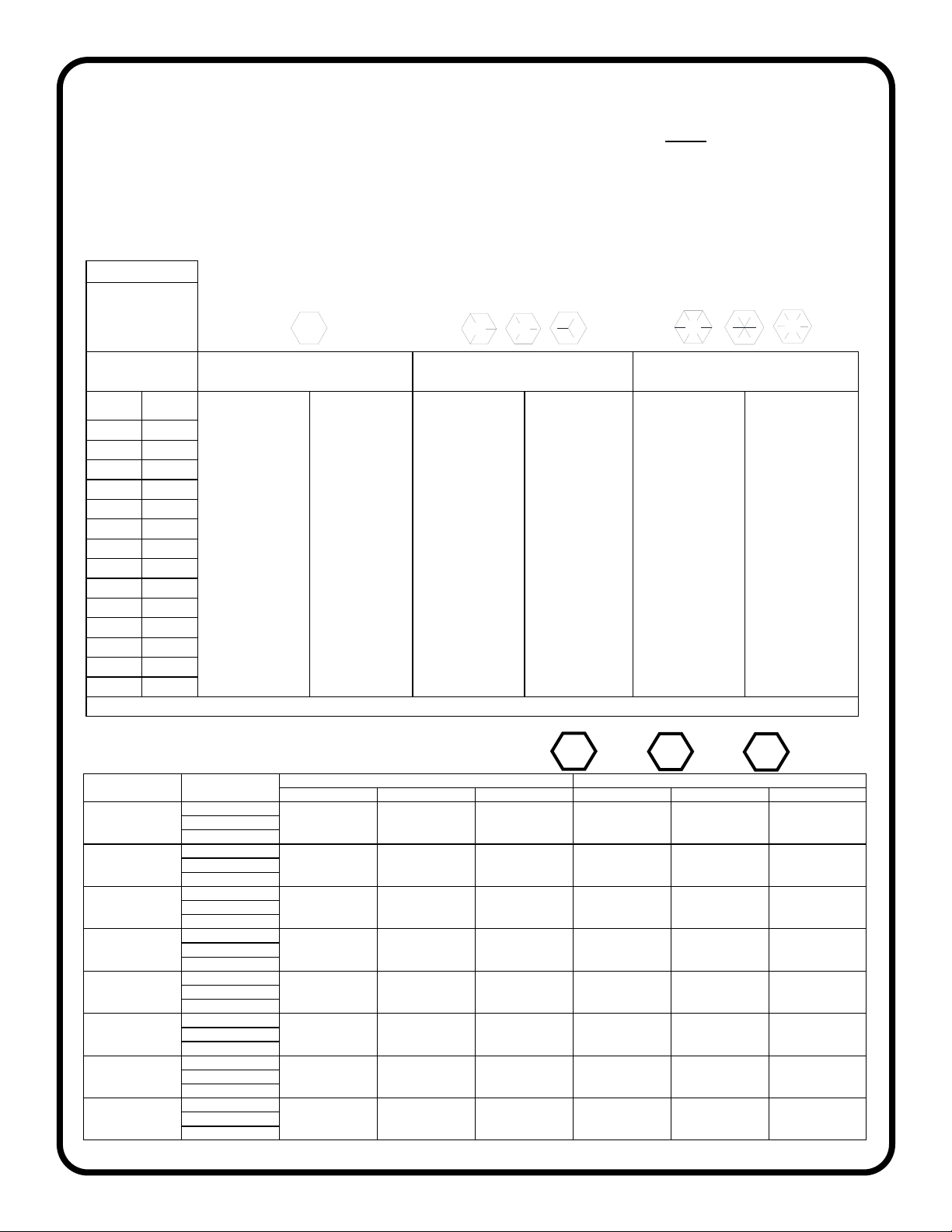
Torque Specs. for Structural Bolts
This page is for use primarily when dealing with high-strength vehicle fasteners such as ROPS hardware that hold the
structure together for safety. This page can also be used for other solid metal-to-metal joints. Do not use these high torque
values on any of the following applications involving: tubing, plastic, nylon or rubber washers, threaded inserts, etc.. See next
page regarding less critical fasteners.
The values below apply to fasteners that are dry or lubricated with normal engine oil. They do not apply if special graphited or
moly disulphide greases or other extreme pressure lubricants are used. This applies to both UNF and UNC threads.
Remember to always use the same grade or property class when replacing bolts.
IMPORTANT: on all PLATED GRADE 8 bolts, reduce torque 15% from listed bolt torque specification.
Size of Screw Property Class
Course Thread Fine Thread
Pitch (mm) Pounds Feet Newton-Meters Pitch (mm) Pounds Feet Newton-Meters
M6
5.6
1.0
3.6-5.8 4.9-7.9
-
- -
8.8 5.8-9.4 7.9-12.7 - -
10.9 7.2-10 9.8-13.6 - -
M8
5.6
1.25
7.2-14 9.8-19
1.0
12-17 16.3-23
8.8 17-22 23-29.8 19-27 25.7-36.6
10.9 20-26 27.1-35.2 22-31 29.8-42
M10
5.6
1.5
20-25 27.1-33.9
1.25
20-29 27.1-39.3
8.8 34-40 46.1-54.2 35-47 47.4-63.7
10.9 38-46 51.5-62.3 40-52 54.2-70.5
M12
5.6
1.75
28-34 37.9-46.1
1.25
31-41 42-55.6
8.8 51-59 69.1-79.9 55-68 75.9-92.1
10.9 57-66 77.2-89.4 62-75 84-101.6
M14
5.6
2.0
49-56 66.4-75.9
1.5
52-64 70.5-86.7
8.8 81-93 109.8-126 90-106 122-143.6
10.9 96-109 130.1-147.7 107-124 145-168
M16
5.6
2.0
67-77 90.8-104.3
1.5
69-83 93.6-112.5
8.8 116-130 157.2-176.2 120-138 162.6-187
10.9 129-145 174.8-196.5 140-158 189.7-214.1
M18
5.6
2.0
88-100 119.2-136
1.5
100-117 136-158.5
8.8 150-168 203.3-227.6 177-199 239.8-269.6
10.9 175-194 237.1-262.9 202-231 273.7-313
M20
5.6
2.5
108-130 146.3-176.2
1.5
132-150 178.9-203.3
8.8 186-205 252-277.8 206-242 279.1-327.9
10.9 213-249 288.6-337.4 246-289 333.3-391.6
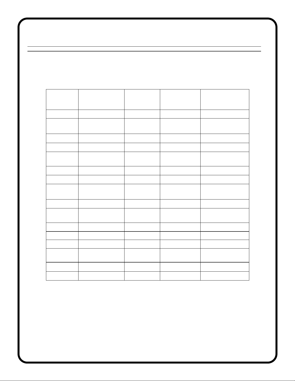
METRIC BOLT TORQUE SPECIFICATIONS 5.6 8.8 10.9
SAE Grade No.
Bolt head identification
mark as per grade.
NOTE: Manufacturing
Marks Will Vary
TORQUE TORQUE TORQUE
Bolt Size Pounds Feet Newton-Meters Pounds Feet Newton-Meters Pounds Feet Newton-Meters
Inches Millimeters Min. Max. Min. Max. Min. Max. Min. Max. Min. Max. Min. Max.
1/4 6.35 5678911 12 15 12 15 16 20
5/16 7.94 10 12 14 16 17 20.5 23 28 24 29 33 39
3/8 9.53 20 23 27 31 35 42 48 57 45 54 61 73
7/16 11.11 30 35 41 47 54 64 73 87 70 84 95 114
1/2 12.70 45 52 61 70 80 96 109 130 110 132 149 179
9/16 14.29 65 75 88 102 110 132 149 179 160 192 217 260
5/8 15.88 95 105 129 142 150 180 203 244 220 264 298 358
3/4 19.05 150 185 203 251 270 324 366 439 380 456 515 618
7/8 22.23 160 200 217 271 400 480 542 651 600 720 814 976
125.40 250 300 339 406 580 696 787 944 900 1080 1220 1464
1-1/8 25.58 - - - - 800 880 1085 1193 1280 1440 1736 1953
1-1/4 31.75 - - - - 1120 1240 1519 1681 1820 2000 2468 2712
1-3/8 34.93 - - - - 1460 1680 1980 2278 2380 2720 3227 3688
1-1/2 38.10 - - - - 1940 2200 2631 2983 3160 3560 4285 4827
*Thick Nuts must be used with Grade 8 bolts
58*
2

9 of 9
Tightening of Non-Structural Bolts
For light or medium duty fastening, Curtis recommends using a general industry standard of tightening until snug and then
giving an additional one quarter turn of the tool as deemed reasonable for the application (i.e.: at the installer’s discretion).
If torque values are required, the examples listed below are intended as a reasonable reference for use in the majority of
non-structural fastener applications such as: small diameter fasteners; bolts passing thru tubing, glass, plastic, nylon or
rubber washers, threaded inserts, etc.
If more than one application below applies, use the lower torque value.
FASTENER
SIZE:
FASTENER
TYPE:
WASHER
MATERIAL: APPLICATION:
TORQUE
(INCH-POUNDS)
(±5)
#10 Machine Screws - in Nylon P-Clamps 20
#10 Machine Screws - Strobe Light
(plastic base) 35
M5 Set Screws - Wiper Arm 20
1/4” Cap Nut - Windshield Wiper 20
1/4” Bolts - Tubing
(5/8” to 3/4” wide) 132
1/4” Bolts Rubber - 60
1/4” Bolts Nylon / Plastic - 72
1/4” Bolts - Factory Installed
Threaded Inserts 132
5/16” Bolts - Tubing (1” or wider) 60
5/16” Flat Head Bolts - Plastic Windshield
Hinge 79
5/16” Bolts Rubber - 120
5/16” Bolts Nylon / Plastic - 150
5/16” Ball Studs - - 150
5/16” Bolts - Factory Installed
Threaded Inserts 240
3/8” Bolts - Tubing 120
M12 Door Striker Pins - - 120
Other manuals for 1POLXP1000DR
1
Table of contents
Other Curtis Automobile Accessories manuals

Curtis
Curtis Polaris Ranger 1000 Roof Kit Operating instructions

Curtis
Curtis 1POLXP1000WS Operating instructions

Curtis
Curtis 47587421001 Operating instructions

Curtis
Curtis 1POLXP1000RP Operating instructions

Curtis
Curtis Polaris XP900 Operating instructions

Curtis
Curtis XP 900 Operating instructions

Curtis
Curtis 1POLXP1000DR Operating instructions

Curtis
Curtis 47587417001 Operating instructions

Curtis
Curtis 47587420001 Operating instructions

Curtis
Curtis 47587416001 Operating instructions