Curtis enGage II 3000 Series User manual

1
enGage II:Programmable Battery Discharge
Indicator
3003R-57X-0001
Description
AMP
Pin #
(V+) Supply voltage positive
terminal
4
(V-) Supply voltage negative
terminal
8
Key switch (+): When V+ is
applied this switch operates the
gauge display.
6
MOSFET output: MOSFET
(0.5A) open drain type internally
tied to V-.
7
Setup Enable (+): When V+
applied, gauge can be
programmed via panel buttons.
2
Hour Meter Enable (+): When
V+ applied, accumulation of
time occurs when key switch on.
3
AutoRange Switch (-):
No connection = 24 04 48 VDC;
Connection = 12 or 36 VDC
1
Technical Specifications
Operating Voltage Range 12V-48VDC nominal voltage, +/-
25%
Operating Current Range Nominal- 14 mA, maximum 20
mA. Values reflect key switch in "on" position
Display: LCD with 10-segment bar and 5 digit numeric
(5mm high)
Hour Meter Range: 99,999 Total Hours
Hardware: Mounting Bracket
Panel Cutout: 52 mm / 2 1/16" diameter
Shock SAE J 1378 Amplitude
44-55 g, half sine, 9-13 ms duration
Vibration SAE J 1378 Double amplitude of 1.53mm with
frequency sweep for 10-80-10 Hz (20 g max) at 1 minute
intervals
Storage Temperature: -50°C to +90°C
Operating Temperature: -40°C to +85°C
Humidity: 95% RH (non-condensing)
IP Rating: 65 Front & Rear with AMP connector installed

2
Entering the Configuration Mode
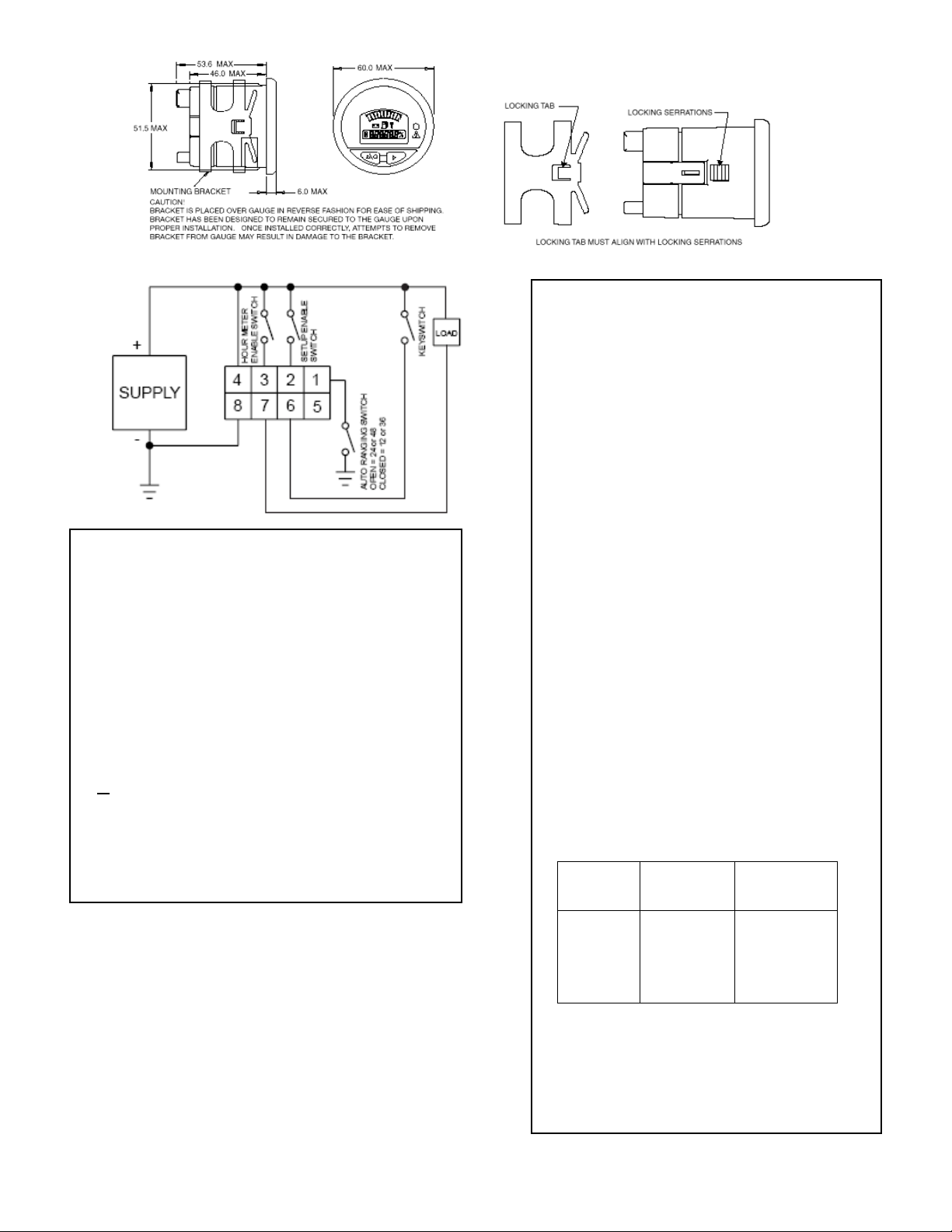
To change the Battery Discharge Profile V+ must be
connected to the set up pin (2). After V+ is applied to
pin 2 press and hold the left button until the time of day
clock flashes the 4 clock digits. If no change in clock
setting is desired use the left button to progress to the
discharge profile
Configuring Your Gauge
Access to these operations is sequential in this order.
Adjustments of the following functions can be
performed in the Configuration Mode:
1. Time-of-Day Clock
2. Battery Discharge Indicator Profiles
During configuration, the right button is used to
increment. The left button is used to:
1. Enter a selection
2. Advance to the next configurable item
If no change is desired to a specific gauge function,
continue to press the left button until the next desired
function is reached. The time-of-day clock is entered
by setting the hours digits between 01 and 12, then
"minutes" digits between "00" and "59".
The profile of the BDI is settable with the front panel
buttons.
Setting the Battery Indicator
Profiles
The display flashes the 3 digits of the discharge full
profile. Press the right button to increment by 0.10
VPC or hold the button to increment continuously.
When the display reaches 2.30 it will automatically
restart at 1.80 VPC. When the desired reset profile
setting is reached, press the left button once.
The display flashes the 3 digits of the discharge empty
profile. Press the right button to increment by 0.10
VPC or hold the button to increment continuously.
When the display reaches 2.20 it will automatically
restart at 1.50 VPC. When the desired reset profile
setting is reached, press the left button once.
Setting the Time-of-Day Clock
The display will flash the two "Hours" digits. Press the
right button to increment by one hour, or hold the
button to increment continuously. When the desired
number of hours is reached, press the left button once.
The display will flash the two "Minutes" digits. Press
the right button to increment by one minute or hold the
button to increment continuously. When the desired
number of minutes is reached, press the left button
once.
Configuration Notes
The gauge remains in configuration mode for 30
seconds without input from the user. When configuring
each function (time-of-day, BDI Profile), you must
enter in all data for that function for it to be saved. If
incomplete data is entered for a function and the
programming mode is timed out (after 30 seconds of
no input received by the gauge), the gauge will revert
back to what was previously stored for that item.
1 0
Exiting Configuration Mode
The configuration mode can be exited in three ways:
1. Press and hold the left button for three seconds.
2. Leave buttons untouched for 30 seconds.
3. Press the left button after selecting the last (right)
digit of the last function available.
Operation
When the main power (9-60 VDC) is applied to V+ and
V-, a power-up sequence is initiated. All display
segments are illuminated for one second. The display
is then turned off until the key switch is activated.
Toggling Display Functions
Press the left button to sequentially toggle between the
three numeric gauge functions (time-of-day clock,
maintenance hours, total hours).
Setting/Changing the Time-of-
Day Clock
This can be done without V+ applied to Setup Enable
pin. Press and hold the left button on the front panel
until the entire display flashes and then release.
Resetting the BDI
OCR- Open circuit reset
The BDI will reset when the gage is
disconnected from the discharged battery and
reconnected to a fully charged battery.
CTR – Charge Tracking Reset
Battery state-of-charge will be tracked by the
Gauge during the charging period.

3
LCD Icons
1. Hourglass Icon -Turned on (not blinking) to
indicate that an hour meter is displayed in the numeric
display. Flashes to indicate hour meter accumulation.
2. Battery Icon – Turned on (not blinking) to
indicate function. It flashes when a low condition is
detected.
3. Colon -Flashes to indicate that the time-of-
day clock is being displayed in the numeric display and
that time is counting-up.
4. Decimal Point -To indicate 1/10 of a volt for
the BDI profile
5. Percent -Indicates remaining percentage of
interval or level.
Troubleshooting
Problem Possible Causes
No Display Terminals not connected
Improper voltage
Stays at Full Instrument voltage does not match
battery voltage
V+ connected to wrong terminal
Will not reset Instrument voltage does not match
battery voltage
Battery not fully charged
Defective battery
Resets without charging Not connected to battery
terminal
Empty too soon V+ connected to wrong terminal
Instrument voltage does not match
battery voltage
Terminals not connected to battery
Cannot configure No power to the setup enable pin
Notes
1. Mating connector; 8-pin AMP, P/N 794821-1
with UL rating 94V-0. Interface seal, P/N
794772-0. Wire seal 794758-
1, Pins
P/N770904-X for #18-24 AWG.
2. Material: Case-polycarbonate, lens-clear
polymethylmethacrylat (PMMA) cover,
overlay and mounting bracket-polycarbonate.
3. This unit is designed for a mounting panel
thickness of 0.8mm-6.4mm.
4. Panel cutout: 52mm diameter dash panel
hole.
Maintenance
The enGage™II 3000 Series is not serviceable.
Safety Instructions
This instrument was manufactured and tested
according to the applicable technical standards. It
complies with all the safety regulations as shipped
from the factory.
Installation and startup must be performed by skilled
personnel.
Failure to install and operate the unit in accordance
with these instructions may result in damage or injury.
If safe operation of the instrument can no longer be
ensured, stop and secure it against accidental
operation.
If instrument failure or malfunction may cause
personal injury or material damage, use additional
safety measures such as limit switches, guards, etc.
Read the Operating Instructions carefully before
startup.
Note the safety instructions marked with this
warning symbol in this manual.
Guarantee
Curtis Instruments’ products and/or components are
guaranteed against defects in workmanship and
material for a period of two years, or as defined in the
individual product literature, from date of shipment
from our factory, when applied in a proper application
within specified ratings. This guarantee is limited to
repair or replacement F.O.B. our factory. There is no
further warranty or implied representation, guarantee,
promise or agreement as to any Curtis Instruments
product and/or component. Curtis Instruments, Inc.,
cannot assume responsibility or accept invoices for
unauthorized repairs to its products and/or
components, even though defective. In no case will
Curtis Instruments’ responsibility extend to products,
components or equipment not of its manufacture.
Under no circumstances shall Curtis Instruments, Inc.
be liable for any special or consequential damages or
loss of profits or other damages. Returned goods will
not be accepted unless identified by a Curtis Return
Material Authorization (RMA). All specifications are
subject to change without notice.

4
Installation
Caution!
Bracket has been designed to remain secured to the
gauge upon proper installation. Once installed
correctly, attempts to remove bracket from gauge
may result in damage to the bracket.
Curtis enGage™ II instruments are mounted in a
52mm round cutout. Serrations on the barrel of the
gauge, combined with the mounting bracket
provided, insure fast and trouble free installation. To
insure proper installation, the 2 locking tabs on
either side of the inner diameter of the bracket
should aligned with the serrations on the barrel of
the gauge (see drawing above). Next, slide the
bracket over the barrel of the gauge and press it
firmly against back of panel. You should hear the tab
sliding over the serrations.
Curtis enGage™ II mates with an 8-pin AMP
connector (AMP pins P/N 770904-X FOR #18-24
AWG P/N 794821-1). A preassembled mating
connector kit (Curtis P/N 17631800-01) with crimp-
connect terminated wires (approx. 5 inches in
length) is also available.
Output and Warning LED
Function
LED
Activated
FET
Opens
BDI
LMB
LMB
KEY
1. RMB = Right Most LCD Bar
2. LMB = Left Most LCD Bar.
Installation Procedure
1. Mount unit in standard SAE round cutout.
2. Connect supply voltage to pins indicated: (V+) pin 4,
(V-) pin 8.
3. Connect pin 6, as appropriate for key switch, to enable
gauge display.
4. Connect pin 3 as appropriate to activate the hour
meter.
5. Connect pin 2 to a programming enable switch.
6. If battery is 12 or 36 VDC connect pin 1 to battery (-).
7. Connect pin 7 to an audio, visual, horn, or other warning
device (load). Caution:Max current draw on warning
device is 0.5 Amps.
This manual suits for next models
1
Table of contents
Other Curtis Measuring Instrument manuals