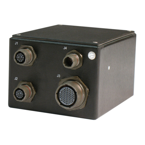
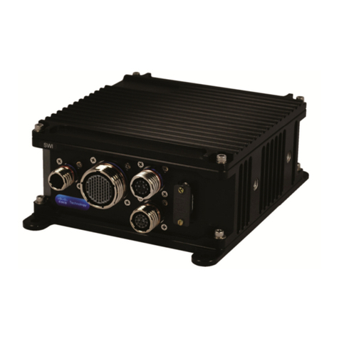
Curtiss-Wright DuraNET 3300 User manual

24x 1000BASE-T w/PoE+ and 2x 10GBASE-SR
USER MANUAL
DuraNET 3300
Rugged Cisco ESS-3300 L2/L3 Ethernet Switch

User Manual –DuraNET 3300
Page 2 of 84
MNL-0676-01 Rev A4
ECO- N/A
Effective: 26 Feb 21
Disclaimer
Although the information contained herein has been carefully verified, Curtiss-Wright assumes no responsibility for errors that might
appear in this document or for damage to property or persons resulting from improper use of this manual or related software.
Curtiss-Wright reserves the right to change the contents and form of this document, as well as the features and specifications of its
products, at any time without notice. The information in this publication does not represent a commitment on the part of Curtiss-
Wright. This document contains proprietary information that is protected by copyright. All rights are reserved. No part of this
document may be photocopied, reproduced, or translated into another language without the prior written consent of Curtiss-Wright.
Contact Information
Curtiss-Wright
Defense Solutions Division
3222 S. Washington St.
Salt Lake City, Utah, USA 84115
T: +1.801.483.1533
Toll-Free: +1.800.483.3152
F: +1.801.483.1523
Email:
Sales: slp_sales@curtisswright.com
Support: slp_tsupport@curtisswright.com
Web-site: www.curtisswrightds.com
Send us your comments and feedback: slp_feedback@curtisswright.com
Trademarks
Parvus is a brand of Curtiss-Wright Corporation.
All trademarks, both marked and not marked, appearing in this document are the property of their respective owners.
Copyright
© 2021 Curtiss-Wright
This document was reviewed on 2020.11.19 and does not contain technical data.

User Manual –DuraNET 3300
Table of Contents
MNL-0676-01 Rev A4
ECO- N/A
Effective: 26 Feb 21
Page 3 of 84
Table of Contents
Table of Contents......................................................................................................................3
List of Figures...........................................................................................................................5
List of Tables.............................................................................................................................6
Chapter 1 Introduction..............................................................................................................7
About This Document....................................................................................................................................7
Manual Organization ..............................................................................................................................7
Definitions...............................................................................................................................................7
Description of Safety Symbols................................................................................................................7
Functional Description...................................................................................................................................8
Features........................................................................................................................................................9
Cisco Technology..........................................................................................................................................9
Rugged MIL-STD Design..............................................................................................................................9
Target Applications .......................................................................................................................................9
Configurations.............................................................................................................................................10
Architecture Block Diagram.........................................................................................................................12
Chapter 2 Quick-Start Guide..................................................................................................13
Starter Breakout Cable Sets .......................................................................................................................14
Cable Install and Connections ....................................................................................................................15
Accessing the CLI through the Console Port..............................................................................................16
Software Terminal Emulator and Serial Console Setup.......................................................................16
Linux:..............................................................................................................................................16
Windows:........................................................................................................................................18
Execute and Configure the PuTTY installer................................................................................................18
Running PuTTY...........................................................................................................................................21
Setting an Open Firewall Port.....................................................................................................................29
USB Console Port.................................................................................................................................31
Linux:..............................................................................................................................................31
Windows:........................................................................................................................................32
RS-232 Console Port............................................................................................................................32
Recommended Settings..............................................................................................................................33
Chapter 3 Connector Descriptions ........................................................................................34
Connector Identification ..............................................................................................................................34
Connector Pinouts.......................................................................................................................................35
J1 Power Connector.............................................................................................................................36
J2 Copper I/O Connector......................................................................................................................38
J3 Copper I/O Connector......................................................................................................................42
J4 Optical I/O Connector ......................................................................................................................47
Chapter 4 Operational Description........................................................................................48
Configure IP Address, User Name and Password......................................................................................48
Updating Cisco IOS-XE Version .................................................................................................................49
Install TFTP Server (Linux)...................................................................................................................51
Loading a new Image ...........................................................................................................................56

User Manual –DuraNET 3300
Table of Contents
Page 4 of 84
MNL-0676-01 Rev A4
ECO- N/A
Effective: 26 Feb 21
Select a Cisco IOS Software Image ......................................................................................................56
PoE Type1 and PoE+ Type2 Functionality and Power Check ...................................................................58
Zeroization or Declassification....................................................................................................................62
Command Line Interface ......................................................................................................................62
Zeroization Trigger................................................................................................................................63
Recovery Procedures...........................................................................................................................63
Chapter 5 Specifications ........................................................................................................65
Mechanical & Technical Specifications.......................................................................................................65
Dimensions...........................................................................................................................................65
Physical ................................................................................................................................................65
Installation & Mounting................................................................................................................................66
Orientation............................................................................................................................................66
Choosing a Mounting Location –Thermal Considerations ..................................................................66
Vertical Mounting..................................................................................................................................66
Horizontal Mounting..............................................................................................................................67
Grounding.............................................................................................................................................68
Power....................................................................................................................................................69
Environmental Specifications......................................................................................................................69
Temperature.........................................................................................................................................69
Shock/Vibration.....................................................................................................................................69
EMI/EMC Compliance ..........................................................................................................................69
Operating Conditions............................................................................................................................70
Cisco Specifications....................................................................................................................................70
Other Specifications....................................................................................................................................74
Reliability ..............................................................................................................................................74
Export Jurisdiction ................................................................................................................................74
Regulatory Compliance ........................................................................................................................74
Warranty......................................................................................................................................................74
Chapter 6 Troubleshooting ....................................................................................................75
Product Identification...................................................................................................................................75
Technical Assistance ..................................................................................................................................75
Returning for Service ..................................................................................................................................75
Chapter 7 Contact Info............................................................................................................76
Appendix A..............................................................................................................................77
Firefox Browser Issue and Correction.........................................................................................................77
Minicom Client Install and Setup - Ubuntu..................................................................................................78
iperf Install and Setup –Linux Ubuntu........................................................................................................79
Automated Diagnostic Software Install and Execute..................................................................................80
DuraNET 3300 Port to Cisco Name Mapping.............................................................................................82
Glossary ..................................................................................................................................83

User Manual –DuraNET 3300
List of Figures
MNL-0676-01 Rev A4
ECO- N/A
Effective: 26 Feb 21
Page 5 of 84
List of Figures
Figure 1.1: DuraNET 3300 Architecture Block Diagram............................................................................12
Figure 2.1: Cable Diagram..........................................................................................................................15
Figure 2.2: Minicom Term ...........................................................................................................................16
Figure 2.3: Minicom Serial Setup................................................................................................................16
Figure 2.4: Minicom Baud...........................................................................................................................17
Figure 2.5: Minicom Default........................................................................................................................17
Figure 2.6: PuTTY Install ............................................................................................................................18
Figure 2.7: PuTTY Destination....................................................................................................................19
Figure 2.8: PuTTY Features........................................................................................................................19
Figure 2.9: PuTTY Completed ....................................................................................................................20
Figure 2.10: PuTTY Configuration ..............................................................................................................21
Figure 2.11: PuTTY COM Port Assigned....................................................................................................21
Figure 2.12: PuTTY Configuration with COM # ..........................................................................................22
Figure 2.13: Console Prompt......................................................................................................................22
Figure 2.14: Null Modems...........................................................................................................................32
Figure 2.15: DuraNET 3300 switch> prompt ..............................................................................................33
Figure 3.1: EAU Front View ........................................................................................................................34
Figure 3.2: Production Front View ..............................................................................................................35
Figure 3.3: J1 EAU Pin Arrangement..........................................................................................................36
Figure 3.4: J1 Production Pin Arrangement................................................................................................37
Figure 3.5: J2 Pin Arrangement..................................................................................................................38
Figure 3.6: J3 Pin Arrangement..................................................................................................................42
Figure 3.7: J4 Pin Arrangement..................................................................................................................47
Figure 4.1: Show Configuration Listing .......................................................................................................50
Figure 4.2: Show Boot Listing .....................................................................................................................50
Figure 4.3: Update APT package repository cache....................................................................................51
Figure 4.4: Install the tftpd-hpa package.....................................................................................................51
Figure 4.5: tftpd-hpa package installed.......................................................................................................52
Figure 4.6: Check whether the tftpd-hpa service is running. ......................................................................52
Figure 4.7: tftpd-hpa is running...................................................................................................................53
Figure 4.8: Modify the /etc/default/tftpd-hpa configuration file....................................................................53
Figure 4.9: Configuration file editing. ..........................................................................................................54
Figure 4.10: Adding the --create option. .....................................................................................................54
Figure 4.11: Create a new directory............................................................................................................55
Figure 4.12: Change the owner and group.................................................................................................55
Figure 4.13: Restart the tftpd-hpa service...................................................................................................55
Figure 4.14: Enter command to check that tftpd-hpa service is running. ...................................................55
Figure 4.15: tftpd-hpa is running.................................................................................................................56
Figure 4.16: Max PoE Power vs Temperature.............................................................................................58
Figure 4.17: minicom IP address ................................................................................................................59
Figure 4.18: DUT Login Window. ................................................................................................................60
Figure 4.19: DUT Login Window. ................................................................................................................60
Figure 4.20: Click Yes to continue. .............................................................................................................61
Figure 4.21: PoE power consumption box..................................................................................................61
Figure 5.1: Front Panel Dimensions ...........................................................................................................65
Figure 5.2: Mounting Holes.........................................................................................................................66
Figure 5.3: Side Mounting Holes.................................................................................................................67
Figure 5.4: Rear View Grounding Hole.......................................................................................................68

User Manual –DuraNET 3300
List of Tables
Page 6 of 84
MNL-0676-01 Rev A4
ECO- N/A
Effective: 26 Feb 21
List of Tables
Table 1.1: EAU System Configurations ......................................................................................................10
Table 1.2: EAU Breakout I/O Cable Configurations....................................................................................10
Table 1.3: Production System Configurations.............................................................................................11
Table 1.4: Production Breakout I/O Cable Configurations..........................................................................11
Table 2.1: DuraNET 3300 Breakout Cables, Cisco Ports and Port Labels ................................................13
Table 2.2: Physical Cable Labels vs Cisco Port Numbers/Long Names....................................................14
Table 3.1: EAU Connector Identification & Part Numbers..........................................................................34
Table 3.2: Production Connector Identification & Partnumbers..................................................................35
Table 3.3: J1 EAU Connector Information..................................................................................................36
Table 3.4: J1 Connector Pinout ..................................................................................................................36
Table 3.5: Phoenix Power Cables...............................................................................................................37
Table 3.6: J1 Production Connector Information ........................................................................................37
Table 3.7: J1 Connector Pinout ..................................................................................................................37
Table 3.8: J2 EAU Connector Information..................................................................................................38
Table 3.9: J2 Production Connector Information ........................................................................................38
Table 3.10: J2 Connector Pinout –By Pin Number....................................................................................38
Table 3.11: J2 Connector Pinout –By Function .........................................................................................40
Table 3.12: J3 EAU Connector Information ................................................................................................42
Table 3.13: J3 Production Connector Information ......................................................................................42
Table 3.14: J3 Connector Pinout –By Pin Number....................................................................................42
Table 3.15: J3 Connector Pinout –By Function .........................................................................................45
Table 3.16: J4 Connector Information.........................................................................................................47
Table 3.17: J4 Connector Pinout ................................................................................................................47
Revision History Table
REVISION HISTORY
Rev
Date
Page(s) /
Section(s) Affected
Detailed Description of Changes
-
*
All
Creation
A1
10/20/2020
All
Initial Release
A2
10/29/2020
44
Table 3.14, Pin 78 from: P16.MDI2_N to: P16.MDI1_N
A3
10/30/2020
6, 40
Added this Table.
Corrected Figure 3.5, pins 20&28 incorrect location.
A4
2/25/2021
15, 33, 35, 37, 38,
42, 47, 48, 65, 66,
67, 68, 74
Updated cable connection diagram (Figure 2.1). Added
“Recommended Settings” section for post-zeroization
setting changes. Removed references to Amphenol
connectors, updated optical connector PN. Corrected J1
power pinout. Added links to Cisco manuals and IOS-XE
software releases. Updated mechanical
dimensions/mounting section. Removed references to
EN55xxx testing.

User Manual –DuraNET 3300
Introduction
MNL-0676-01 Rev A4
ECO- N/A
Effective: 26 Feb 21
Page 7 of 84
Chapter 1 Introduction
The Parvus® DuraNET® 3300 is a MIL-rugged 26-port Cisco IOS-managed L2/L3 switch integrating the
Cisco® Systems ESS-3300 Embedded Services Switch in a robust design optimized for the harshest
deployed military, aerospace, and industrial applications.
About This Document
Manual Organization
This manual provides functional and technical descriptions of the DuraNET 3300 hardware, instructions
on connecting the system to test equipment, connector descriptions and pinouts, and specifications.
•Chapter 1 provides an introduction and function description of the DuraNET-3300
•Chapter 2 provides a Quick Start Guide.
•Chapter 3 contains connector pinouts and part numbers for all external connectors and their
mating connector
•Chapter 4 explains how to operate the DuraNET 3300. It describes the system connectors and
cables, and includes procedures for starting the system, and usage of the zeroization capabilities.
•Chapter 5 provides chassis specifications, dimensions, and mounting instructions. In addition, it
provides the technical and environmental specifications for the DuraNET 3300.
•Chapter 6 provides troubleshooting instructions and technical support contact information
•Chapter 7 provides additional contact information.
Definitions
Please refer to the Glossary at the end of this document for an explanation of terms.
Description of Safety Symbols
The following symbols are used in this manual to indicate important information and potentially dangerous
situations.
Warning! Danger, electrical shock hazard!
Personal injury or death could occur. Also damage to the system, connected peripheral devices, or
software could occur if the warnings are not followed carefully.
Caution! Hazard to individuals, environment, devices, or data!
If you do not adhere to the safety advice next to this symbol, there is obvious hazard to individuals, to
environment, to materials, or to data.
Note: This symbol highlights important information or instructions that should be observed.

User Manual –DuraNET 3300
Introduction
Page 8 of 84
MNL-0676-01 Rev A4
ECO- N/A
Effective: 26 Feb 21
Functional Description
The Parvus® DuraNET® 3300 is a MIL-rugged 26-port Cisco IOS-managed L2/L3 switch integrating
Cisco® Systems’ “Hellcat” Embedded Services Switch (ESS-3300) in a robust design optimized for the
harshest deployed military, aerospace, and industrial applications. With a small form factor (SFF), fan-
less and IP67-rated design, this 1G / 10G (24 x 1000BASE-T + 2 x 10GBASE-SR) ultra-rugged
Commercial-Off the Shelf (COTS) network device provides up to 44 Gbps of line-rate multi-layer
forwarding, along with advanced network security, data, video and voice services supported by Cisco
IOS® software. The DuraNET 3300 serves as an ideal high bandwidth connectivity solution for size,
weight, power and cost (SWaP-C)-sensitive vehicle and aircraft platforms exposed to harsh
environmental and noisy conditions (e.g. high altitude, extreme shock and vibe, extended temperatures,
humidity, dust and water exposure, noisy EMI, dirty power). Integrated EMI and power filtering comply
with civil / military vehicle and aircraft requirements, including power input voltage, spikes, surges,
transients, and EMI/EMC compatibility requirements per MIL-STD-704F, MIL-STD-1275D, MIL-STD-
461F, and RTCA/DO-160. The unit also delivers support for PoE (Power-Over-Ethernet) devices (i.e. IP
cameras, IP phones) and MIL-STD-704 hold-up capabilities for aircraft power switch-over requirements.
Not only does the DuraNET 3300 deliver an ultra-reliable and SWaP-optimized design, it notably delivers
the latest in Cisco’s ESS-3300 IOS-managed Gigabit and 10 Gigabit Ethernet connectivity for a devices
installed at the tactical network edge on-board unmanned air/ground vehicles (UAVs, UGVs), helicopters,
fixed-wing aircraft, tactical ground vehicles and other SWaP-constrained platforms deploying Ethernet
backbones. With Cisco Network Essentials (switching) or Network Advantage software (switching +
routing) software license options, the unit can support fully managed Layer 2/3 switching and dynamic
routing with a comprehensive set of enterprise-grade networking features for robust and secure network
services including efficient multicasting, flexible Quality of Service (QoS), precision timing (IEEE-1588),
and a range of security features, such as MACsec, secure boot, and zeroize, etc)
Housed in a sealed IP67-rated (dust + water proof) aluminum chassis with MIL-DTL-38999 circular
connectors, the DuraNET 3300 combines rugged robust mechanical design with high-performance
networking, delivering new capabilities for situational awareness and Command, Control,
Communications, Computers, Intelligence, Surveillance and Reconnaissance (C4ISR) applications. Built
with industrial-temperature components, this compact system supports a wide ambient operating
temperature range of -40 to +71°C (-40 to +160ºF) without fans or cold plate. It thrives in extreme
shock/vibration conditions, high altitude, and humidity, making it well suited for mobile, tactical,
aerospace, and ground vehicle applications. The unit will undergo extensive qualification testing to MIL-
STD-810G, MILSTD-461F, MIL-STD-1275D, MIL-STD-704F and RTCA/DO-160G conditions for
environmental, power and EMI compatibility (thermal, shock, vibration, dust, water, humidity, altitude,
power spikes/ surges, conducted/radiated emissions & susceptibility.

User Manual –DuraNET 3300
Introduction
MNL-0676-01 Rev A4
ECO- N/A
Effective: 26 Feb 21
Page 9 of 84
Features
•Small form factor L2/L3 Ethernet Switch
•24x ports of Gigabit 1000BASE-T (copper) interfaces + optional 2 x ports of 10 Gigabit 10GBASE-
SR (fiber optic) ports for trunking / uplinks / long hauls / EMI immunity. USB 2.0 console, RS232
console, zeroize discrete input, and optional 50ms holdup for core switch (not for PoE power)
•SWaP-optimized
oSize: ~ 150 in³ volume; ~ 2U high
oWeight: ~ 5.6 lb (2.52 kg)
oPower: < 50 W, excluding PoE
Cisco Technology
•Integrated 10G/1G Cisco Embedded Services Switch (ESS-3300) cards
•Cisco IOS-XE with Network Essentials or Network Advantage license options
•Data, video, and voice service features for security, QoS, and high availability: TCP, UDP, Telnet,
IGMP, IP, RADIUS, SNMP, RMON, DHCP, HTTPS, VLAN, WEBUI Device Manager, Industrial
Network Director (IND), IEEE-1588v2 time-stamping, Media Access Control Security (MACsec)
•Optional Layer 3 IP Services support for dynamic routing: Inter-VLAN Routing, Open Shortest Path
First (OSPF), Enhanced Interior Gateway Routing Protocol (EIGRP), Routing Information Protocol
(RIP), Intermediate System to Intermediate System (IS-IS), Protocol Independent Multicast (PIM)
Rugged MIL-STD Design
•MIL-STD-810G and DO-160G environmental qualifications (shock, vibration, thermal, altitude,
humidity, ingress)
•Filtered, transient and EMI-protected MIL-STD-1275/704/ DO-160 compliant power supply for aircraft
and vehicle “dirty power” input; support for PoE injected IP phones and cameras; 50ms power hold-
up option
•MIL-STD-461F and DO-160 EMI/EMC (conducted and radiated emissions and susceptibility)
•-40 to +71°C fan-less extended temp operation with no moving parts (passive natural convection)
•Corrosion-resistant, aluminum chassis sealed for water immersion, dust exposure (equivalent to IP67
rating)
•High-performance MIL-circular connectors
•Conformal coating for humidity/tin-whisker mitigation
Target Applications
•High throughput in-vehicle / airborne L2/L3 Ethernet switching and routing in harsh temperature and
vibration environments (for onboard computers, cameras, sensors, monitoring devices,
communications, and command-and-control equipment)
•Civil and military SWaP-sensitive Communications - On the Move (C-OTM) systems for mobile,
tactical, airborne, and vehicle platforms, enhancing situational awareness and network centric
operations at network edge (i.e. UAV, UAS, UGV, helicopter, aircraft, vehicle, maritime vessels,
outdoor, underground)

User Manual –DuraNET 3300
Introduction
Page 10 of 84
MNL-0676-01 Rev A4
ECO- N/A
Effective: 26 Feb 21
•C4ISR technology refresh on retrofit / new platforms
•ITAR-free export, U.S. Commerce EAR controlled
•Commercial and military aerospace platforms requiring compliance to MIL-STD-810G, MIL-STD-
461F, MIL-STD- 1275D, MIL-STD-704F, CE Mark, RTCA/DO-160
Configurations
Details on DuraNET 3300 Early Access Unit (EAU) and Production configurations follow. Both EAUs and
Production units share the same form factor and function, but have different power connectors and
external connector coatings.
EAU system and cable set configurations include:
Table 1.1: EAU System Configurations
Product Number
Description
NET-3300-01H-E
DuraNET 3300 Ethernet Switch, 24 x 1000BASE-T with 50 ms switch
holdup, Network Essentials IOS, EAU
NET-3300-02-E
DuraNET 3300 Ethernet Switch, 24 x 1000BASE-T, 2 x 10GBASE-SR,
Network Essentials IOS, EAU
NET-3300-11-E
DuraNET 3300 Ethernet Switch, 24 x 1000BASE-T, Network Advantage
IOS, EAU
Table 1.2: EAU Breakout I/O Cable Configurations
Product Number
Description
CBL-NET-3300-01-E
Starter cable set for DuraNET 3300, 24 x GbE, Mating Circular Connectors
to RJ-45/USB/DB9, EAU
CBL-NET-3300-02-E
Starter cable set for DuraNET 3300, 24 x GbE, 2 x 10G, Mating Circular
Connectors to RJ-45/USB/DB9/Fiber-LC, EAU

User Manual –DuraNET 3300
Introduction
MNL-0676-01 Rev A4
ECO- N/A
Effective: 26 Feb 21
Page 11 of 84
Production system and cable set configurations include:
Table 1.3: Production System Configurations
Product Number
Description
NET-3300-01
DuraNET 3300 Ethernet Switch, 24 x 1000BASE-T, Network Essentials IOS
NET-3300-01H
DuraNET 3300 Ethernet Switch, 24 x 1000BASE-T with 50 ms switch holdup,
Network Essentials IOS
NET-3300-02
DuraNET 3300 Ethernet Switch, 24 x 1000BASE-T, 2 x 10GBASE-SR, Network
Essentials IOS
NET-3300-02H
DuraNET 3300 Ethernet Switch, 24 x 1000BASE-T, 2 x 10GBASE-SR with 50
ms switch holdup, Network Essentials IOS
NET-3300-11
DuraNET 3300 Ethernet Switch, 24 x 1000BASE-T, Network Advantage IOS
NET-3300-11H
DuraNET 3300 Ethernet Switch, 24 x 1000BASE-T with 50 ms switch holdup,
Network Advantage IOS
NET-3300-12
DuraNET 3300 Ethernet Switch, 24 x 1000BASE-T, 2 x 10GBASE-SR, Network
Advantage IOS
NET-3300-12H
DuraNET 3300 Ethernet Switch, 24 x 1000BASE-T, 2 x 10GBASE-SR with 50
ms switch holdup, Network Advantage IOS
Table 1.4: Production Breakout I/O Cable Configurations
Product Number
Description
CBL-NET-3300-01
Starter cable set for DuraNET 3300, 24 x GbE, Mating Circular Connectors to
RJ-45/USB/DB9
CBL-NET-3300-02
Starter cable set for DuraNET 3300, 24 x GbE, 2 x 10G, mating circular
connectors to RJ-45/USB/DB9/Fiber-LC

User Manual –DuraNET 3300
Introduction
Page 12 of 84
MNL-0676-01 Rev A4
ECO- N/A
Effective: 26 Feb 21
Architecture Block Diagram
Figure 1.1: DuraNET 3300 Architecture Block Diagram

User Manual –DuraNET 3300
Quick-Start Guide
MNL-0676-01 Rev A4
ECO- N/A
Effective: 26 Feb 21
Page 13 of 84
Chapter 2 Quick-Start Guide
This section describes the physical configuration and quick-start operational testing of
the DuraNET 3300. You will need two computers with at least a single USB port and
single network connection.
Tables 2.1 and Table 2.2 list the relationship between cables, cable port labels, and
Cisco port definitions.
Table 2.1: DuraNET 3300 Breakout Cables, Cisco Ports and Port Labels
J2 CBL-2884-01
J3 CBL-2885-01
Cisco
Port
Cable
Label
Cisco
Port
Cable
Label
Cisco
Port
Cable
Label
Gi1/3
P3
Gi2/1
P11
Gi2/9
P19
Gi1/4
P4
Gi2/2
P12
Gi2/10
P20
Gi1/5
P1
Gi2/3
P9
Gi2/11
P17
Gi1/6
P2
Gi2/4
P10
Gi2/12
P18
Gi1/7
P7
Gi2/5
P15
Gi2/13
P23
Gi1/8
P8
Gi2/6
P16
Gi2/14
P24
Gi1/9
P5
Gi2/7
P13
Gi2/15
P21
Gi1/10
P6
Gi2/8
P14
Gi2/16
P22
Note: J4 optical ports Te1/1 and Te1/2 assigned to LC1 and LC2 respectively.

User Manual –DuraNET 3300
Quick-Start Guide
Page 14 of 84
MNL-0676-01 Rev A4
ECO- N/A
Effective: 26 Feb 21
Table 2.2: Physical Cable Labels vs Cisco Port Numbers/Long Names
Physical Cable Label
Cisco Software Shorthand Name
Cisco Software Long Name
LC1
Te1/1
Tengigabitethernet1/1
LC2
Te1/2
Tengigabitethernet1/2
P1
Gi1/5
Gigabitethernet1/5
P2
Gi1/6
Gigabitethernet1/6
P3
Gi1/3
Gigabitethernet1/3
P4
Gi1/4
Gigabitethernet1/4
P5
Gi1/9
Gigabitethernet1/9
P6
Gi1/10
Gigabitethernet1/10
P7
Gi1/7
Gigabitethernet1/7
P8
Gi1/8
Gigabitethernet1/8
P9
Gi2/3
Gigabitethernet2/3
P10
Gi2/4
Gigabitethernet2/4
P11
Gi2/1
Gigabitethernet2/1
P12
Gi2/2
Gigabitethernet2/2
P13
Gi2/7
Gigabitethernet2/7
P14
Gi2/8
Gigabitethernet2/8
P15
Gi2/5
Gigabitethernet2/5
P16
Gi2/6
Gigabitethernet2/6
P17
Gi2/11
Gigabitethernet2/11
P18
Gi2/12
Gigabitethernet2/12
P19
Gi2/9
Gigabitethernet2/9
P20
Gi2/10
Gigabitethernet2/10
P21
Gi2/15
Gigabitethernet2/15
P22
Gi2/16
Gigabitethernet2/16
P23
Gi2/13
Gigabitethernet2/13
P24
Gi2/14
Gigabitethernet2/14
Starter Breakout Cable Sets
Cable sets are made of the following individual cable assemblies:
•CBL-2883-01 CBL LAB DURANET 3300 POWER J1 80IN
•CBL-2884-01 CBL LAB DURANET 3300 8X1G J2 80IN
•CBL-2885-01 CBL LAB DURANET 3300 16X1G J3 80IN
•CBL-2886-01 CBL LAB DURANET 3300 10G-SR J4 80IN

User Manual –DuraNET 3300
Quick-Start Guide
MNL-0676-01 Rev A4
ECO- N/A
Effective: 26 Feb 21
Page 15 of 84
Cable Install and Connections
Figure 2.1: Cable Diagram
1. Connect a power cable (CBL-2883-01) to port J1 on the DuraNET 3300 and the other end of the
cable to the unpowered DC power source.
2. Connect network cable (CBL-2884-01) to port J2 on the DuraNET 3300
a. Connect either the RS-232 or USB communication link to PC1 USB or serial port.
3. Connect network cable (CBL-2885-01) to port J3 on the DuraNET 3300
4. Connect Optical cable (CBL-2886-01) to port J4 on the DuraNET 3300

User Manual –DuraNET 3300
Quick-Start Guide
Page 16 of 84
MNL-0676-01 Rev A4
ECO- N/A
Effective: 26 Feb 21
Accessing the CLI through the Console Port
You can enter Cisco IOS commands and parameters through the CLI, by using one of the console
connections. Note: if both the USB and RS-232 are connected, the USB takes precedence.
•USB Console Port
•RS-232 Console Port
Software Terminal Emulator and Serial Console Setup
Prior to communicating with the DuraNET 3300, software installation and setup must be performed to
ensure proper communication. The installation instructions will be tailored for both Windows 10 and Linux
operating systems for multi-user preference and experience.
See appendix A for the install of required software
Linux:
•Open a terminal window. If this is the first time opening a terminal window you will need
to set the baud rate for the console port. If this is not the first time you can simply enter
“sudo minicom”
•From the terminal window prompt enter the following command
▪~$ sudo minicom –s
▪password for parvus: parvus “if asked for a password”
Figure 2.2: Minicom Term
•Use the up and down arrow keys to select “Serial port setup” in the [configuration] menu
▪Serial port setup
Figure 2.3: Minicom Serial Setup

User Manual –DuraNET 3300
Quick-Start Guide
MNL-0676-01 Rev A4
ECO- N/A
Effective: 26 Feb 21
Page 17 of 84
•Under setup option enter Eand change the Bps/Par/Bits to
▪9600 8N1
Figure 2.4: Minicom Baud
•Then save as default and exit
Figure 2.5: Minicom Default
•To confirm correct configuration and communication link
▪Hit <return> and confirm the Cisco CLI prompt is displayed
oSwitch>

User Manual –DuraNET 3300
Quick-Start Guide
Page 18 of 84
MNL-0676-01 Rev A4
ECO- N/A
Effective: 26 Feb 21
Windows:
First-time use of Windows will require installation of a USB driver, terminal emulator, console and
IP address setup.
•USB Driver
▪Connection of either the USB or RS232 console cables will initiate an auto USB
CP2102 driver load. User interaction during this process is not required.
•Download the PuTTY Terminal Emulator (or equivalent, i.e. TeraTerm) and Serial
Console Application software and following the instructions
•www.putty.org
▪Download PuTTY installation
oPuTTY-64bit-0.74-installer
▪Software installation can be accomplished by following the instructions from the
URL page.
ohttps://www.ssh.com/ssh/putty/windows/install
Execute and Configure the PuTTY installer
Open the Windows Explorer (right-click on the Windows logo in the bottom left corner), navigate to the
Downloads directory (or wherever you saved the installer), and double-click on the file name. Note,
however, that the installation has to be performed with Administrator rights (either using the Administrator
account or your personal account must have Administrator permissions).
When the installer starts, it shows the welcome screen. Just click Next.
Figure 2.6: PuTTY Install

User Manual –DuraNET 3300
Quick-Start Guide
MNL-0676-01 Rev A4
ECO- N/A
Effective: 26 Feb 21
Page 19 of 84
The installer then asks for the Destination folder in which to install the software. Almost always it is best to
use the default value. Just click Next.
Figure 2.7: PuTTY Destination
Then, the installer asks to select product features to install. You probably want to add a shortcut on the
desktop if you expect to use the software frequently. All the other options generally should be enabled.
When ready, click Install.
Figure 2.8: PuTTY Features

User Manual –DuraNET 3300
Quick-Start Guide
Page 20 of 84
MNL-0676-01 Rev A4
ECO- N/A
Effective: 26 Feb 21
When the installation has completed successfully, it should show a "Completed" screen. Click Finish to
exit the installer.
Figure 2.9: PuTTY Completed
Table of contents
Other Curtiss-Wright Switch manuals

Curtiss-Wright
Curtiss-Wright Parvus DuraMAR 5915-3X User manual

Curtiss-Wright
Curtiss-Wright Parvus DuraNET 20-11 User manual

Curtiss-Wright
Curtiss-Wright Parvus DuraNET 30-2020 User manual

Curtiss-Wright
Curtiss-Wright Parvus SWI-22-10-10 User manual

Curtiss-Wright
Curtiss-Wright DuraNET 1059 User manual