Curtiss-Wright Parvus DuraNET 30-2020
MNL-0654-01 Rev B3 ECO-5370 Effective: 19 Jan 18 Page 3 of 33
T
ABLE OF
C
ONTENTS
Chapter 1 Introduction.............................................................................................................6
About This Document.................................................................................................................................... 6
Description of Safety Symbols................................................................................................................ 6
Functional Description................................................................................................................................... 7
Features.................................................................................................................................................. 8
Cisco Technology............................................................................................................................. 8
IOS Management ............................................................................................................................. 8
Rugged MIL-STD Design ................................................................................................................. 8
Configurations......................................................................................................................................... 9
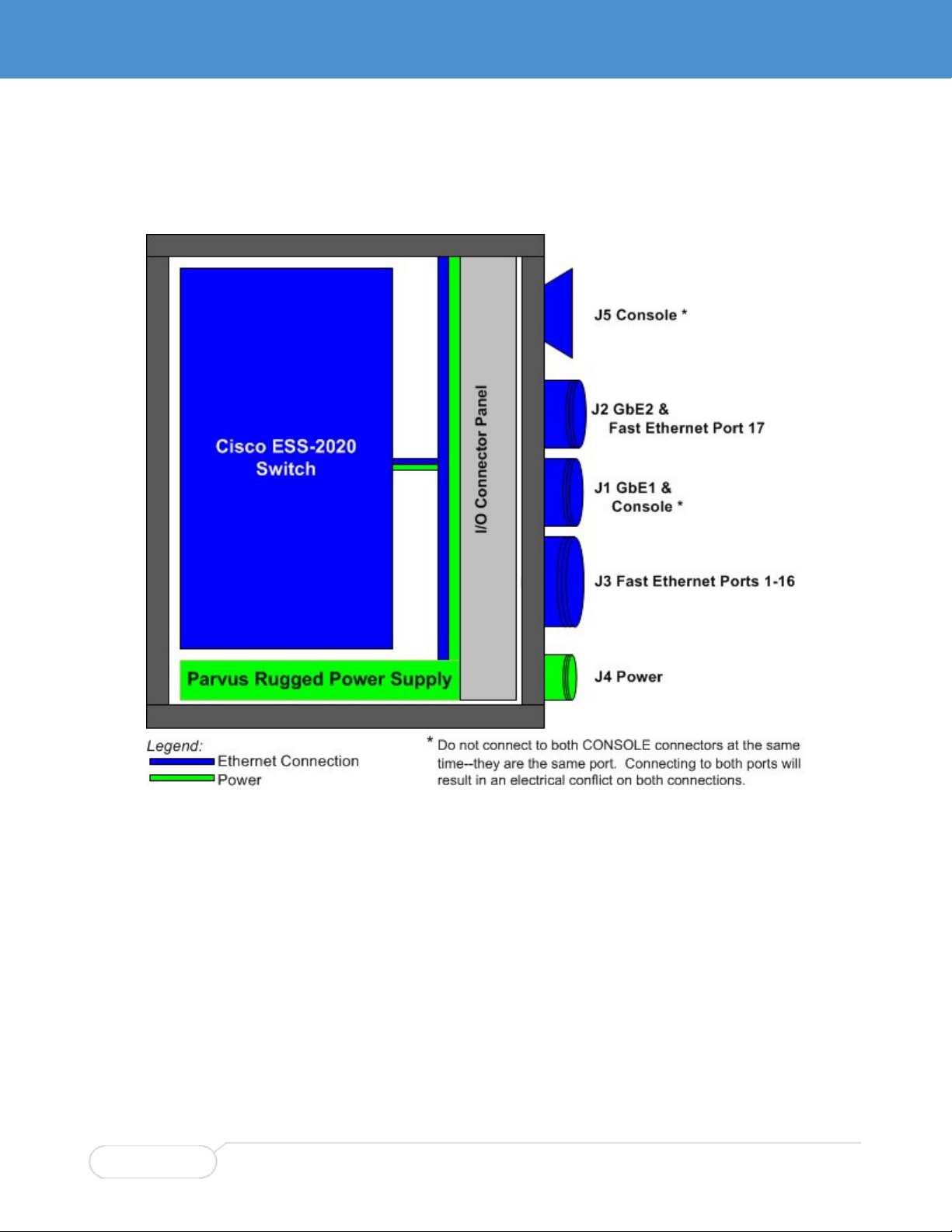
Block Diagram ...................................................................................................................................... 10
Chapter 2 Operational Description .......................................................................................11
Connector Identification .............................................................................................................................. 11
Front Panel ........................................................................................................................................... 11
Rear Panel............................................................................................................................................ 12
Test Equipment Installation......................................................................................................................... 12
Breakout Cable Set .............................................................................................................................. 13
Power-on Sequence ............................................................................................................................. 14
Switch Configuration ................................................................................................................................... 15
Mounting the DuraNET 30-2020 ................................................................................................................. 15
Thermal Considerations for Choosing a Mounting Location ................................................................ 15
Vertical Mounting .................................................................................................................................. 16
Horizontal Mounting.............................................................................................................................. 17
Grounding ............................................................................................................................................. 18
Chapter 3 Connector Descriptions .......................................................................................19
Connector Identification .............................................................................................................................. 19
Connector Location and Mapping......................................................................................................... 19
Circular Connector Part Numbers ........................................................................................................ 20
Pinouts ........................................................................................................................................................ 21
J1 Gigabit Ethernet (1 Port) and Serial Console (1 Port) ..................................................................... 21
J2 Gigabit Ethernet (1 Port) and 10/100Base-T (1 Port) ...................................................................... 22
J3 Ethernet 10/100Base-T (16 Ports)................................................................................................... 23
J4 Power............................................................................................................................................... 24
J5 Console............................................................................................................................................ 24
Chapter 4 Specifications .......................................................................................................25
Technical Specifications.............................................................................................................................. 25
Cisco Technology ................................................................................................................................. 25
Ports ..................................................................................................................................................... 25
Performance ......................................................................................................................................... 25
Layer 2 Switching ................................................................................................................................. 25
Multicast................................................................................................................................................ 25
Management......................................................................................................................................... 26
Security................................................................................................................................................. 26
Quality of Service.................................................................................................................................. 26
Layer 3 Routing .................................................................................................................................... 26
Reliability .............................................................................................................................................. 26