Curtiss-Wright Parvus DuraMAR 5915-3X User manual

USER MANUAL
Parvus®DuraMAR 5915-3X
Rugged Cisco 5915 Mobile Access Router combined with
Parvus SWI-22-10 Gigabit Ethernet Switch
MNL-0659-01 Rev A7 ECO-5592 Effective: 05 Feb 19

Chapter 1 Introduction
User Manual, MAR-5915-3x
Page 2 of 39
MNL-0659-01 Rev A7
ECO-5592
05 Feb 19
Disclaimer
Although the information contained herein has been carefully verified, Curtiss-Wright assumes no responsibility for errors that might
appear in this document or for damage to property or persons resulting from improper use of this manual or related software.
Curtiss-Wright reserves the right to change the contents and form of this document, as well as the features and specifications of its
products, at any time without notice. The information in this publication does not represent a commitment on the part of Curtiss-
Wright. This document contains proprietary information that is protected by copyright. All rights are reserved. No part of this
document may be photocopied, reproduced, or translated into another language without the prior written consent of Curtiss-Wright.
Contact Information
Defense Solutions Division
Curtiss-Wright
3222 S. Washington St.
Salt Lake City, Utah, USA 84115
Phone: +1 (801) 483-1533
Toll-Free: +1 (800) 483-3152
Fax: +1 (801) 483-1523
Email:
Sales: slp_sales@curtisswright.com
Support: slp_tsupport@curtisswright.com
Web-site: www.curtisswrightds.com/parvus
Send us your comments and feedback: slp_feedback@curtisswright.com
Trademarks
Parvus is a brand of Curtiss-Wright Corporation.
All trademarks, both marked and not marked, appearing in this document are the property of their respective owners.
Copyright
© 2015 Curtiss-Wright

User Manual, MAR-5915-3x
Chapter 1 Introduction
MNL-0659-01 Rev A7
ECO-5592
Effective: 05 Feb 19
Page 3 of 39
Table of Contents
Chapter 1 Introduction.............................................................................................................6
About This Document....................................................................................................................................6
Description of Safety Symbols................................................................................................................6
Functional Description............................................................................................................................7
Features..................................................................................................................................................8
Configurations.........................................................................................................................................9
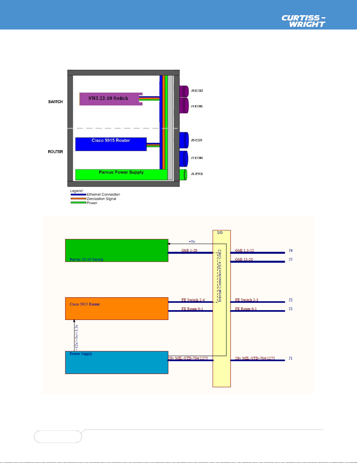
Block Diagram ......................................................................................................................................10
Chapter 2 Operation...............................................................................................................11
Breakout Cable Set.....................................................................................................................................11
Quick Start Steps ........................................................................................................................................13
Support Equipment...............................................................................................................................13
Connections..........................................................................................................................................13
IOS Configuration and Upgrade..................................................................................................................14
Vitesse CE Services Configuration.............................................................................................................14
Vitesse CE Services Upgrade.....................................................................................................................14
Zeroization...................................................................................................................................................15
Enabling Zeroization for the Cisco 5915 (ROU)...................................................................................15
Enabling Zeroization for the Parvus SWI-22-10 (SWI).........................................................................15
Initiating Zeroization .............................................................................................................................16
Zeroization Recovery............................................................................................................................17
Loading the ROU IOS Image after Zeroization ....................................................................................17
Loading the ROU IOS Configuration after Zeroization.........................................................................18
Loading the SWI configuration after Zeroization ..................................................................................18
Installation...................................................................................................................................................19
Orientation............................................................................................................................................19
Choosing a Mounting Location –Thermal Considerations ..................................................................19
Vertical Mounting..................................................................................................................................20
Horizontal Mounting..............................................................................................................................21
Grounding.............................................................................................................................................22
Chapter 3 Connector and LED Descriptions........................................................................23
ROU ring .....................................................................................................................................................23
Connector Identification and Mapping..................................................................................................23
J1 PWR Pinouts....................................................................................................................................24
J2 ETH 0 Pinouts..................................................................................................................................25
J3 CON Pinouts....................................................................................................................................26
LED Indicator Descriptions...................................................................................................................27
SWI ring.......................................................................................................................................................28
Connector Identification and Mapping..................................................................................................28
J4 ETH1 Pinout.....................................................................................................................................29
J5 ETH2 Pinout.....................................................................................................................................30
Chapter 4 Specifications......................................................................................................................31
SWI Ring...............................................................................................................................................31
ROU Ring .............................................................................................................................................32
System..................................................................................................................................................34

Chapter 1 Introduction
User Manual, MAR-5915-3x
Page 4 of 39
MNL-0659-01 Rev A7
ECO-5592
05 Feb 19
Chapter 4 Environmental Specifications..............................................................................36
Thermal.................................................................................................................................................36
Shock....................................................................................................................................................36
Vibration................................................................................................................................................36
Humidity................................................................................................................................................36
Sealing..................................................................................................................................................36
Altitude..................................................................................................................................................36
EMI/EMC ..............................................................................................................................................36
Input Voltage.........................................................................................................................................36
Chapter 5 Troubleshooting ...................................................................................................37
Product Identification...................................................................................................................................37
Technical Assistance ..................................................................................................................................37
Returning for Service ..................................................................................................................................37
Chapter 6 Contact Info...........................................................................................................38

User Manual, MAR-5915-3x
Chapter 1 Introduction
MNL-0659-01 Rev A7
ECO-5592
Effective: 05 Feb 19
Page 5 of 39
List of Figures
Figure 1 –ROU ring cables.........................................................................................................................11
Figure 2 –SWI ring cables* ........................................................................................................................11
Figure 3. Mounting Holes...........................................................................................................................20
Figure 4. Side Mounting Holes...................................................................................................................21
Figure 5. Rear View ...................................................................................................................................22
Figure 6. MAR-5915-3x Connectors ..........................................................................................................23
Figure 7. Connector J1 Power ...................................................................................................................24
Figure 8. Connector J2 ETH 0 ...................................................................................................................25
Figure 9. Connector J3 CON......................................................................................................................26
Figure 10. J2 LED Mapping to J2 Signal Name and Cisco Port Name .....................................................27
Figure 11. Front Panel Dimensions ...........................................................................................................35

Chapter 1 Introduction
User Manual, MAR-5915-3x
Page 6 of 39
MNL-0659-01 Rev A7
ECO-5592
05 Feb 19
Chapter 1 Introduction
About This Document
This document serves as a manual for the MAR-5915-3x products. The MAR-5915-3x systems comprise
a MAR-5915-0x and a DUNET-20-10-01 in one system. These two elements have separate manuals
(MNL-0596A-01 & MNL-0653A-01 respectively) which describe the operation of the standalone systems.
This manual covers the design elements and features that are unique to the combined system.
Description of Safety Symbols
The following symbols are used in this manual to indicate important information and potentially dangerous
situations.
Warning! Danger, electrical shock hazard!
Personal injury or death could occur. Also damage to the system, connected peripheral devices, or
software could occur if the warnings are not followed carefully.
Caution! Hazard to individuals, environment, devices, or data!
If you do not adhere to the safety advice next to this symbol, there is obvious hazard to individuals, to
environment, to materials, or to data.
Note: This symbol highlights important information or instructions that should be observed.

User Manual, MAR-5915-3x
Chapter 1 Introduction
MNL-0659-01 Rev A7
ECO-5592
Effective: 05 Feb 19
Page 7 of 39
Functional Description
The MAR-5915-3X family combines the functionality of MAR-5915-0X and DuraNET 2010 by combining
them in a single system. An internal connection links these two components. MAR-5915 port FE 0/4 is
internally connected to SWI-22-10 card port GE2. The Cisco 5915 router is physically housed in the
DuraSTAX™ring labeled ROU, hereafter referred to as the ROU ring. The SWI-22-10 switch card is also
physically housed in the DuraSTAX™ring labeled SWI, hereafter referred to as the SWI ring.

Chapter 1 Introduction
User Manual, MAR-5915-3x
Page 8 of 39
MNL-0659-01 Rev A7
ECO-5592
05 Feb 19
Features
ROU Ring - Cisco Technology
Ruggedized Cisco 5915 Router with 2x routed 10/100Base-T and 2x switched 10/100Base-T
ports.
Enterprise IOS Software for robust security, management, QoS, VLAN, IPv4/IPv6 routing, IP
mobility, interoperability
Integrated Services Router (ISR) features support concurrent data, video, and voice services, as
well as firewall and hardware AES encryption acceleration
SWI Ring
Integrated Parvus SWI 22-10 CE Services managed Ethernet switch with 19x GigE Ethernet
ports (plus one additional GbE port internally connecting switch and router).
Carrier Ethernet Services software deliver rich Layer 2 switch features, Layer 3 Aware packet
processing, service classification and traffic policing; IEEE-1588 precision timing protocol and
hardware accurate timestamping
Layer 2 network management: 10/100/1000 Mbps Gigabit Ethernet connectivity, IPv4 / IPv6
Multicast, VLAN, QoS/CoS Traffic Prioritization, Multiple/Rapid Spanning Tree, Link Aggregation,
IEEE-1588 Precision Timing Protocol
Layer 3 IPv4 / IPv6 Unicast Static Routing support for IP routing to attached WAN / radios
SNMPv3, HTTP Server, web GUI, RS-232 console CLI, Port Monitoring, RMON, Syslog, Network
Access Server (NAS), 802.1X Authentication, IGMP Snooping, Access Control Lists (ACLs),
zeroization, built-in test (BIT) diagnostics
Rugged MIL-STD Design
Qualified for MIL-STD-810G and DO-160G conditions (temp, shock, vibration, humidity, altitude,
dust/water ingress)
Qualified for MIL-STD-461F and DO-160G EMI/EMC (Conducted & Radiated Emissions &
Susceptibility) and MIL-STD-1275 & 704 Power Input and Transient Protections
Filtered, transient-protected power supply for aircraft and vehicle use
Extended temperature, open architecture PC104-sized circuit card assemblies with near
cableless internal interconnect for shock and vibration extremes
Conformal coated internal boards for humidity, corrosion, and tin-whisker mitigation
-40 to +71C fanless extended temp operation with no moving parts
Corrosion-resistant, aluminum chassis sealed (IP67) against water, dust, EMI
Circular MIL-DTL-38999 connectors for reliable network connections
Data Zeroization support to erase sensitive information
Flexible/robust mounting –base flange mount or side boss mount

User Manual, MAR-5915-3x
Chapter 1 Introduction
MNL-0659-01 Rev A7
ECO-5592
Effective: 05 Feb 19
Page 9 of 39
Configurations
All MAR-5915-3X systems incorporate a Parvus SWI-22-10 with the CES Management software
(equivalent to the standalone DuraNET 20-10-01). The MAR-5915 Router portion is available with either a
Base IOS or Advanced IOS. Advanced IOS versions can be ordered with optional CME license for 5, 25
or 50 users.
Product Number
Description
MAR-5915-30
DuraMAR 5915 Router w/DuraNET 20-10 GigE Switch(MAR-5915-00+DUNET-
20-10-01), 5915 BaseIOS
MAR-5915-31
DuraMAR 5915 Router w/DuraNET 20-10 GigE Switch(MAR-5915-01+DUNET-
20-10-01), 5915 AdvIOS
MAR-5915-32
DuraMAR 5915 Router w/DuraNET 20-10 GigE Switch(MAR-5915-02+DUNET-
20-10-01), 5915 AdvIOS CME5*
MAR-5915-33
DuraMAR 5915 Router w/DuraNET 20-10 GigE Switch(MAR-5915-03+DUNET-
20-10-01), 5915 AdvIOS CME25*
MAR-5915-34
DuraMAR 5915 Router w/DuraNET 20-10 GigE Switch(MAR-5915-04+DUNET-
20-10-01), 5915 AdvIOS CME50*
Note: Advanced IOS software supports CME but the required CME software is not included with these systems because some of
the required files are user equipment specific. All CME software is available from www.cisco.com

Chapter 1 Introduction
User Manual, MAR-5915-3x
Page 10 of 39
MNL-0659-01 Rev A7
ECO-5592
05 Feb 19
Block Diagram
System Block Diagram
Detailed Ethernet and Power Block Diagram

User Manual, MAR-5915-3x
Chapter 2 Operation
MNL-0659-01 Rev A7
ECO-5592
Effective: 05 Feb 19
Page 11 of 39
Chapter 2 Operation
Breakout Cable Set
A breakout cable set (CBL-MAR-5915-30) is available for the system. These cables are suitable for bench
top testing and proof of concept setups. The same cable set works with all -3X models. Final installation
should use custom cables designed for the target environment. Refer to Chapter 3 Connector and LED
Descriptions for information required to design custom cables.
Figure 1 –ROU ring cables
Figure 2 –SWI ring cables*
*power cable shown is not part of the SWI ring cables.

Chapter 2 Operation
User Manual, MAR-5915-3x
Page 12 of 39
MNL-0659-01 Rev A7
ECO-5592
05 Feb 19
The breakout cable set includes the cables listed in Table 1
Table 1
Cable Part #
From
To
Qty
Description
CBL-2417-01
38999 (J1)
Power. External power input cable.
Banana
Plug
3
28V nominal voltage input. Red +, Black -, Green = Chassis
CBL-2418-01
38999 (J2)
ROU 10/100Base-T ports. Five Fast Ethernet ports
RJ-45
2
ROU 10/100Base-T Fast Ethernet Routed 0 & 1
RJ-45
3
ROU 10/100Base-T Fast Ethernet Switched 2,3 & 4*
CBL-2419-01
38999 (J3)
ROU Console and Zeroize Test cable
DB-9
1
ROU RS-232 serial console port cable
Flying
leads
2
ROU/SWI Zeroize** and Ground wire
CBL-2555-01
38999 (J4)
SWI Gigabit Ethernet ports, console port and zeroize
DB-9
1
SWI Console port
RJ-45
12
SWI Gigabit Ethernet ports 1 - 12 (GE1-GE12)***
Button
1
ROU/SWI Zeroize**
CBL-2554-01
38999 (J5)
SWI Gigabit Ethernet ports
RJ-45
8
SWI Gigabit Ethernet ports 13-20 (GE13 –GE20)
CBL-1536-01
DB-9
SWI Console. 6' foot extension RS-232 serial cable
DB-9
1
Use to extend CBL-2419-01 or CBL-2555-01
* The 3rd switched port (P4) is not active on this cable when used with the MAR-5915-3x
** All Zeroize signals are common to SWI and ROU
*** GE2 is not active on this cable when used with the MAR-5915-3x

User Manual, MAR-5915-3x
Chapter 2 Operation
MNL-0659-01 Rev A7
ECO-5592
Effective: 05 Feb 19
Page 13 of 39
Quick Start Steps
Support Equipment
To configure the DuraMAR 5915-3X, you need the following support equipment:
A computer with at least one RS-232 serial port and a terminal emulator application.
Note: The ROU and SWI portions each have a dedicated console port. Each of the two internal
devices (5915 and SWI-22-10) must be configured separately via its unique port.
A DC Power Supply with an output of between 9v and 36v (ideally 28v)
Connections
1. Connect a power cable to port J1 on the DuraMAR 5915-3X (use CBL-2417-01 from the starter cable
set, or an equivalent MIL-DTL-38999 power cable).
2. Connect the other end of the power cable to the unpowered DC power source.
Caution! Make sure that the DC power source is set to provide 9VDC to 36VDC (28V nominal).
3. Connect a serial cable to the serial port on the host PC and to
J3 (for ROU configuration) or (J4 for SWI configuration).
4. Open a terminal emulator on the host PC.
5. In the PC terminal emulation software, for ROU communication, configure the serial port for 9600 bits
per second, 8 data bits, no parity, 1 stop bit, and no flow control. For SWI configuration, configure the
serial port for 115200 bits per second, 8 data bits, no parity, 1 stop bit and no flow control.
6. Apply power.
7. Use the command line interface (CLI) to enter commands to configure the equipment. See the
software configuration guide and command reference from Cisco for more information (refer to the
next section on System Configuration).
8. Connect Ethernet devices as required to J2, J4 and J5.
Refer to Table 1 to determine the correct cable for each connector

Chapter 2 Operation
User Manual, MAR-5915-3x
Page 14 of 39
MNL-0659-01 Rev A7
ECO-5592
05 Feb 19
IOS Configuration and Upgrade
The system is shipped with a Cisco factory-installed IOS on the ROU (5915).
Custom network configuration is the responsibility of the customer. This manual is not intended as a
guide to the Cisco 5915 or IOS. That information is available directly from Cisco Systems at
www.cisco.com. The Cisco website is also the source for Cisco IOS files.
Vitesse CE Services Configuration
The SWI (SWI-22-10) is shipped with Vitesse CE Services Carrier Ethernet application installed. For
guidelines in configuring the switch refer to the Chapter 3 of the DuraNET 20-10 Manual (MNL-0653-01).
Vitesse CE Services Upgrade
This procedure assumes that you have already acquired a .dat upgrade file from the factory.
From a PC connected to the switch, point a browser at 192.168.0.3
Log in using U: admin P: <enter>
On the Left hand side of the screen navigate to Maintenance -> Software -> Upload
Browse to the .dat upgrade file that you want to upgrade with then click <upload>.
New software will be uploaded to the system.

User Manual, MAR-5915-3x
Chapter 2 Operation
MNL-0659-01 Rev A7
ECO-5592
Effective: 05 Feb 19
Page 15 of 39
Zeroization
Caution! The Zeroization function can delete all IOS and configuration files on the system!
Zeroization should only be enabled if it is intended to be used.
Enabling Zeroization for the Cisco 5915 (ROU)
Prior to applying the zeroization signal, the Cisco IOS must be configured to enable zeroization.
From an IOS prompt, enter the following commands:
Router> enable
Router# conf t
Router(config)# service declassify erase-all
Router(config)# exit
The “erase-all” argument will erase all files on the router (flash and NVRAM) when
declassification (zeroization) is invoked
“erase-flash” or “erase-nvram” may be substituted for “erase-all” if only the files in flash memory
or NVRAM, respectively, are to be deleted.
Enabling Zeroization for the Parvus SWI-22-10 (SWI)
Enable zeroization feature using zeroize command.
If the logon prompt appears, then logon with the user name admin and no password.
#conf t
(config)# parvus zeroize

Chapter 2 Operation
User Manual, MAR-5915-3x
Page 16 of 39
MNL-0659-01 Rev A7
ECO-5592
05 Feb 19
Initiating Zeroization
Caution! Hardware triggering of zeroization from either ring (ROU or SWI) will cause the entire
system to be zeroized.
If you only want to zeroize one system, ensure that zeroization is enabled on only that ring –see
above.
Initiating zeroization from the command line (as supported by the SWI ring) only triggers
zeroization of that ring
Hardware Method (ROU & SWI)
Zeroization is triggered by pulling the zeroize signal low (0v).
If you have CBL-2419-01, trigger zeroization by connection the yellow wire (zeroize) to the green
wire (ground).
Caution! This differs from the MAR-5915-0x and -1x systems.
The -0x and -1x systems require 12v to trigger zeroization
DO NOT apply 12v to the zeroize signal on MAR-5915-3x or system damage may occur.
CLI Method (SWI only)
Switch# parvus dozeroize
* dozeroize command may not be supported on early software versions <v1.0.1. If this is the case, upgrade software or use
hardware method described above.

User Manual, MAR-5915-3x
Chapter 2 Operation
MNL-0659-01 Rev A7
ECO-5592
Effective: 05 Feb 19
Page 17 of 39
Zeroization Recovery
After zeroization has occurred you can perform the following steps to reload the system.
Loading the ROU IOS Image after Zeroization
Host PC Setup
1. Identify the target folder used by the tftp server and place the Cisco IOS software image there.
Example IOS filename: c5915-entbase-mz.SPA.152-1.GC1.bin
2. Place the configuration file to be reloaded in the tftp target folder.
3. Attach the host PC to port 0/0 on J2. (This can be the same PC as that running the terminal
emulator.)
4. Set the IP address of the host PC to use the fixed address 192.168.100.11.
5. Open the tftp server on the host PC.
6. Open a terminal emulator on the host PC.
Note: The Solarwinds TFTP server has a file transfer size limit of 32 MB. This is normally not a
problem for the base IOS here. But if the Advanced IOS or other file in excess of 32 MB is
transferred, the file is too large for Solarwinds. The TFTPD32 TFTP server handles the larger file
size without a problem.
Load Procedure
There should be a rommon prompt in the terminal emulator window. If the rommon prompt is not
displayed, reboot the DuraMAR 5915 and wait for the rommon prompt.
1. At the rommon command prompt, type the following CASE-SENSITIVE commands (press Enter after
each command, the filename itself is NOT case-sensitive):
IP_ADDRESS=192.168.100.10
IP_SUBNET_MASK=255.255.255.0
DEFAULT_GATEWAY=192.168.100.11
TFTP_SERVER=192.168.100.11
TFTP_FILE= <IOS filename>
2. At the rommon command prompt, type “set” and Enter. Verify the variables in step 1 have been set
correctly.
3. At the rommon command prompt, type the following CASE-SENSITIVE command and Enter:
tftpdnld
4. At the prompt: “Do you wish to continue y/n: [n],” type y.
5. The IOS will begin transferring to the Cisco 5915. If the transfer does not begin, a message will be
displayed explaining the problem. Fix the problem and repeat the tftpdnld command.
6. When the file transfer is completed, issue a reset command at the rommon prompt.
7. The Cisco 5915 will then reboot and load. After the Cisco 5915 has finished the startup sequence,
press Enter to display the Router> prompt. The Cisco IOS has been successfully reloaded.
8. Now follow the instructions in the next section to reload the IOS configuration.

Chapter 2 Operation
User Manual, MAR-5915-3x
Page 18 of 39
MNL-0659-01 Rev A7
ECO-5592
05 Feb 19
Loading the ROU IOS Configuration after Zeroization
After zeroization, you have to reload your configuration. In these instructions, filename is the name of the
IOS configuration file saved on the host PC, such as 5915config.bin. If you are using a different file, use
that filename in the steps below.
9. Set the router port IP address:
Router> enable
Router# conf t
Router(config)# Interf fast 0/0
Router(config-if)# ip address 192.168.100.10 255.255.255.0
Router(config-if)# no shut
Router(config-if)# exit
Router(config)# exit
Router# copy tftp://192.168.100.11/filename startup-config
Destination filename [startup-config] ?
10. Make sure that the [ok- xxxx bytes] message is displayed. If not, fix the error and repeat the copy tftp
command.
11. Power off the system.
12. Power on the system.
13. After the reload completes, press Enter to display a Router> prompt. The Cisco 5915 IOS
configuration has been successfully reloaded.
Loading the SWI configuration after Zeroization
Zeroization erases the configuration data stored in startup-config. When the switch is restarted after
power down, the switch will start up with the factory-default configuration. You can then reload the user
configuration if you have a backup config file (see MNL-0653-01 Chapter 3), otherwise you have to
reconfigure the switch.
On units that have firmware version 1.0.0, to ensure the system operates properly logon with the user
name admin and no password. Issue the following commands to the console:
configure terminal
Thermal-protect prio 0 temperature 255
Thermal-protect prio 1 temperature 255
Thermal-protect prio 2 temperature 255
Thermal-protect prio 3 temperature 255
hostname SWI-xxxx (xxxx is the serial number)
end
copy running-config startup-config

User Manual, MAR-5915-3x
Chapter 2 Operation
MNL-0659-01 Rev A7
ECO-5592
Effective: 05 Feb 19
Page 19 of 39
Installation
Orientation
The DuraMAR 5915-3X can be mounted either vertically or horizontally and will perform equally well in
either orientation. The target location normally dictates the mounting orientation.
Choosing a Mounting Location –Thermal Considerations
The DuraMAR5915-3X enclosure is highly efficient at removing heat from the inside of the unit to the
outside of the finned enclosure. It is best to mount the unit on a thermally cool, thermally conductive
surface to keep the overall temperature as low as possible. Every effort has been made to meet stringent
thermal performance criteria as outlined in the specifications. However, it is always good practice to keep
the DuraMAR5915-3X as cool as possible, avoiding environments which do not allow the thermal
conduction of heat away from the unit.

Chapter 2 Operation
User Manual, MAR-5915-3x
Page 20 of 39
MNL-0659-01 Rev A7
ECO-5592
05 Feb 19
Vertical Mounting
To install the DuraMAR5915-3X vertically on a mounting surface:
14. Create a hole pattern on the mounting surface that matches the pattern shown in Figure 3. Mounting
Holes. The mounting holes are 0.27” in diameter.
15. Attach the baseplate to the mounting surface using the four mounting holes. Attachment screws
should be 1/4-20.
Important!
Ensure that mounting screw length allows proper thread engagement of the mounting hardware.
Figure 3. Mounting Holes
Table of contents
Other Curtiss-Wright Switch manuals