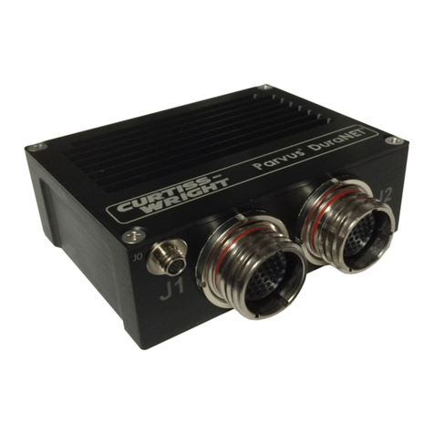
Curtiss-Wright DuraNET 1059 User manual

USER MANUAL
DuraNET 1059
Rugged 5-Port 10/100 Ethernet Switch
PRV-1308-xx
MNL-0571-01 Rev A3 ECO-4895 Effective: 22 Jan 16

DuraNET 1059 User Manual
Page 2 of 31 MNL-0571-01 Rev A3 ECO-48954895 22 Jan 16
Disclaimer
Although the information contained herein has been carefully verified, Curtiss-Wright assumes no responsibility for errors that might
appear in this document or for damage to property or persons resulting from improper use of this manual or related software.
Curtiss-Wright reserves the right to change the contents and form of this document, as well as the features and specifications of its
products, at any time without notice. The information in this publication does not represent a commitment on the part of Curtiss-
Wright. This document contains proprietary information that is protected by copyright. All rights are reserved. No part of this
document may be photocopied, reproduced, or translated into another language without the prior written consent of Curtiss-Wright.
Contact Information
Curtiss-Wright Corporation
3222 S. Washington St.
Salt Lake City, Utah, USA 84115
Phone: +1 (801) 483-1533
Toll-Free: +1 (800) 483-3152
Fax: +1 (801) 483-1523
Email:
Sales: slp_sales@curtisswright.com
Support: slp_tsupport@curtisswright.com
Web-site: www.curtisswrightds.com/parvus
Send us your comments and feedback: slp_feedback@curtisswright.com
Trademarks
Parvus is a brand of Curtiss-Wright Corporation.
All trademarks, both marked and not marked, appearing in this document are the property of their respective owners.
Copyright
© 2016 Curtiss-Wright
WEEE
The information below is issued in compliance with the regulations as set out by the 2002/96/CE directive, subsequently superseded
by 2003/108/CE. It refers to electrical and electronic equipment and the waste management of such products. When disposing of a
device, including all of its components, subassemblies, and materials that are an integral part of the product, you should consider
the WEEE directive.
This symbol has been attached to the equipment or, if that was not possible, on the packaging,
instruction literature, and/or the guarantee sheet. Using this symbol states that the device has been
marketed after August 13th 2005, and implies that you must separate all of its components when
possible, and dispose of them in accordance with local waste disposal legislation.
•Because of the substances present in the equipment, an improper use or disposal of the refuse can cause damage to human
health and to the environment.
•With reference to WEEE, it is compulsory not to dispose of the equipment with normal urban refuse. Arrangements should be
instigated for separate collection and disposal.
•Contact your local waste collection body for more detailed recycling information.
•In case of illicit disposal, sanctions may be levied on transgressors.
RoHS
This device, including all its components, subassemblies, and the consumable materials that are an integral part of the product, has
been manufactured in compliance with the European directive 2002/95/EC known as the RoHS directive (Restrictions on the use of
certain Hazardous Substances). This directive targets the reduction of certain hazardous substances previously used in electrical
and electronic equipment (EEE).

DuraNET 1059 User Manual
MNL-0571-01 Rev A3 ECO-48954895 Effective: 22 Jan 16 Page 3 of 31
Table of Contents
Chapter 1 Introduction............................................................................................................5
Functional Description................................................................................................................................... 5
Block Diagram ............................................................................................................................................... 5
Features ....................................................................................................................................................... 6
Chapter 2 Quick Start-up........................................................................................................8
Installation ..................................................................................................................................................... 8
Connecting to the DuraNET 1059................................................................................................................. 8
Power-up ....................................................................................................................................................... 9
Starter Cable Set......................................................................................................................................... 10
Chapter 3 Connector Descriptions ......................................................................................11
Connector Identification .............................................................................................................................. 11
Connector Part Numbers ............................................................................................................................ 12
Connector Pinouts....................................................................................................................................... 12
J1 Switched Ethernet Port 0 ................................................................................................................. 12
J2 Switched Ethernet Port 1 ................................................................................................................. 13
J3 Switched Ethernet Ports 2 – 4 ......................................................................................................... 13
J4 DC Power......................................................................................................................................... 14
Chapter 4 Specifications ......................................................................................................15
Technical Specifications.............................................................................................................................. 15
Data Transfer........................................................................................................................................ 15
Compliance........................................................................................................................................... 15
Power Requirements ............................................................................................................................ 15
Environmental Specifications ...................................................................................................................... 15
Temperature ......................................................................................................................................... 15
Shock / Vibration................................................................................................................................... 16
Reliability (MTBF)........................................................................................................................................ 16
Mechanical .................................................................................................................................................. 16
Weight................................................................................................................................................... 16
Dimensions ........................................................................................................................................... 16
Mounting Instructions ........................................................................................................................... 18
Chapter 5 Troubleshooting ..................................................................................................19
Product Identification................................................................................................................................... 19
FAQ ............................................................................................................................................................. 20
Technical Assistance .................................................................................................................................. 21
Returning for Service .................................................................................................................................. 21
Maintenance................................................................................................................................................ 21
Chapter 6 Contact Info..........................................................................................................22
Appendix A VLAN Operation................................................................................................23
Port-Based VLAN........................................................................................................................................ 23
VLAN Software Quick Start Setup Guide.................................................................................................... 24
DuraNET 1059 User Manual
Page 4 of 31 MNL-0571-01 Rev A3 ECO-48954895 22 Jan 16
Software Guide ........................................................................................................................................... 25
Com Port............................................................................................................................................... 25
Setting the Egress Ports ....................................................................................................................... 26
Operation of VLAN GUI Window .......................................................................................................... 27
Menu Operation .................................................................................................................................... 28
Glossary ..................................................................................................................................29

DuraNET 1059 User Manual
Chapter 1 Introduction
MNL-0571-01 Rev A3 ECO-48954895 Effective: 22 Jan 16 Page 5 of 31
Chapter 1 Introduction
This section provides a functional description of the DuraNET 1059.
Functional Description
The DuraNET 1059 is a rugged unmanaged Ethernet switch node designed to provide local area network
(LAN) connectivity to IP-enabled computers and other net-centric devices. Weighing in at less than 2 lbs
and hardened with a black anodize finish, internal heatsinking and MIL-38999 connectors, this enclosed
Fast Ethernet switch unit serves as a highly reliable, compact solution for expanding port density
to DuraMAR mobile routers and other netcentric solutions.
Featuring five IEEE 802.3/u complaint (10/100mpbs) Ethernet transceiver ports and support for auto-MDI-
MDIX network installation, the robust DuraNET 1059 requires no configuration and is designed for simple
plug-and-play operation. Any of its five transceiver ports are flexibly designed to serve as an uplink.
Support for auto-crossover, auto-polarity, auto-negotiation, and bridge loop prevention are all integrated.
The DuraNET 1059’s galvanically isolated power supply and Ethernet switch components support
operation from -40°C to +85°C, as well as tolerance to MIL-STD-810F shock and vibration profiles
experienced by helicopter and fixed wing aircraft. Its miniature form factor, low power consumption, and
lightweight chassis make the DuraNET 1059 an ideal Commercial-Off-the-Shelf (COTS) solution for
unmanned/manned airborne or ground vehicle networking applications.
Block Diagram

Chapter 1 Introduction
DuraNET 1059 User Manual
Page 6 of 31 MNL-0571-01 Rev A3 ECO-48954895 22 Jan 16
Features
Ports
•Five Auto-Detecting 10/100BaseT Ethernet
Ports
•Auto-Negotiation Between 10BaseT &
100BaseT
•Auto-MDI/MDIX Crossover
100BaseTX/10BaseT
•Auto-Sensing of Full or Half Duplex on
Each Port
•Any Port Can Serve as Uplink for Network
Expansion
Switching
•Pause Frame-Based Non-Blocking Switch
Fabric
•1,024 MAC Address Look-Up Engine
•Five Fully Independent Media Access
Controllers
•Store-and-Forward Switching
•Integrated 512 Kb Frame Buffer Memory
Management
•Unmanaged Switch; No Configuration Required
Mechanical
•Compact Metal Enclosure •Anodized Coating for Durability
•Conductively Cooled to Outer Case •Connectors: MIL-C-38999 (Ethernet,
Power)
•Mounting via Pemnuts within the Enclosure
Footprint (requires access to the rear of the
mounting panel)
•Unit will meet safety of flight (crash safety)
requirements
•Ingress Protection from Sand, Dust,
Moisture
•Light-weight Approximately 2 Lbs (0.97 Kg)
Power Supply
•Vehicle Grade DC/DC Converter
•Voltage/Surge Protection and EMI Filtering
•MIL-STD-704E Compliant
MilGrade
•
Designed to Meet MIL-STD-810F (Functional Shock, Vibration, Temperature, Humidity
)
Applications

DuraNET 1059 User Manual
Chapter 1 Introduction
MNL-0571-01 Rev A3 ECO-48954895 Effective: 22 Jan 16 Page 7 of 31
•Civil and Military In-Vehicle Networking •Layer 2 Switching in Local Area Network (LAN)
•24/28V Vehicle/Aircraft Installations •Situational Awareness / Net-Centric
Operations
•Unmanaged Switch Port Expansion for a
DuraMAR Router
Options
•CBL-1537-01 - Starter Cable Set with Mating MIL-C-38999 Connectors to RJ-45 & Power, 5-Foot Length
Warranty
•1 Year RTF Warranty (Extended Service Contracts Available)

Chapter 2 Quick Start-up
DuraNET 1059 User Manual
Page 8 of 31 MNL-0571-01 Rev A3 ECO-48954895 22 Jan 16
Chapter 2 Quick Start-up
This section describes the installation of the DuraNET 1059. It then describes the power-up of the
assembly.
The DuraNET 1059 is factory configured to provide five auto detecting IEEE 802.3/u complaint
(10/100mpbs) Ethernet ports. The standard configuration also includes support for auto-crossover, auto-
polarity, auto-negotiation, and bridge loop prevention. Light-weight and designed for rugged
environments, the DuraNET 1059 provides much the same functionality as you would expect in a high
quality off-the-shelf retail switch. The following sections of this chapter assumes the utilization of either
the starter cable set or a custom set of cables made specifically for the intended target system, vehicle, or
craft.
Installation
Test the DuraNET 1059 and cabling or interfaces prior to installation to ensure full operational capability.
Full bench-top testing prior to installing the assembly in the target system can be performed by
purchasing the starter cable set available for this unit.
Installation is made fairly simple with this unit. Please refer to the section in this manual labeled
“Mechanical” for a schematic detailing the mounting dimensions for this assembly and instructions for
mounting the device. The DuraNET 1059 does have shock and random vibration certifications; however
care must be taken in the physical mounting of this device to ensure a solid connection between the
intended target system and this unit is made.
Connecting to the DuraNET 1059
The application diagram shown here provides several examples of typical connections that can be made
with this device.

DuraNET 1059 User Manual
Chapter 2 Quick Start-up
MNL-0571-01 Rev A3 ECO-48954895 Effective: 22 Jan 16 Page 9 of 31
When you connect your network devices, make sure you don’t exceed the maximum cabling distances,
which are listed in the following table:
Table 2.1 Maximum Cabling Distances
From
To
Maximum Distance
Switch Switch or Hub 100 Meters (328 feet)
Switch or Hub Computer 100 Meters (328 feet)
Power-up
Perform the steps in this section to install the hardware and power up the device.
Step 1 Make sure all of the devices you will connect to this unit are powered off.
Step 2 Connect one of either the starter cable set or a custom Ethernet cable to
one of the numbered Ethernet ports (J1 – J3) on the switch. Connect the
other end to a computer or other network device.
Step 3 Repeat step 2 to connect additional devices.
Step 4 Connect an appropriate chassis ground to the supplied mounting lug if
necessary.
Step 5 Connect the appropriate DC power to J4 on the unit and apply power.

Chapter 2 Quick Start-up
DuraNET 1059 User Manual
Page 10 of 31 MNL-0571-01 Rev A3 ECO-48954895 22 Jan 16
Each of the ports can be tested through the use of a simple ping test between two Ethernet capable
devices connected to the DuraNET 1059 to ensure connectivity.
Starter Cable Set
The following cable set is available for purchase through the sales department and is meant to be for lab
or bench testing purposes only.
The main cable set CBL-1537-01 includes the following cables:
CBL-1554-01 Ethernet Port and Serial Cable (Connects to J1)
CBL-1555-01 Single Switch Port Cable – B Key (Connects to J2)
CBL-1556-01 Triple Switch Port Cable (Connects to J3)
CBL-1557-01 External Power Cable (Connects to J4)

DuraNET 1059 User Manual
Chapter 3 Connector Descriptions
MNL-0571-01 Rev A3 ECO-48954895 Effective: 22 Jan 16 Page 11 of 31
Chapter 3 Connector Descriptions
This chapter includes the pinouts and signal descriptions for the DuraNET 1059. Also provided in this
section are connector part numbers along with suggested mating connectors.
Connector Identification
Table 3.1 Connectors
Port
Function
J1 13 pin: 1x Switched Ethernet + spares
J2 13 pin: 1x Switched Ethernet + spares (B keying)
J3 66 pin: 3x Switched Ethernet + spares
J4 3 pin: DC Power
Figure 3.1 Connector Layout
View facing rear panel showing approximate connector locations.

Chapter 3 Connector Descriptions
DuraNET 1059 User Manual
Page 12 of 31 MNL-0571-01 Rev A3 ECO-48954895 22 Jan 16
Connector Part Numbers
The following table shows the manufacturer part numbers for the various connectors fitted to the
DuraNET 1059, together with the recommended mating connections.
Table 3.2 Connector Part Numbers
Port Part Number Mating Connector
J1 D38999/24WB35SN D38999/26WB35PN
J2 D38999/24WB35SB D38999/26WB35PB
J3 D38999/24WF35SN D38999/26WF35PN
J4 D38999/24WA98PN D38999/26WA98SN
Note: Connector J2 has a different keying applied (B keying) to differentiate it from J1 for cabling
purposes.
Connector Pinouts
This section provides the pinouts necessary for creating cables that would properly connect to this
assembly.
Note: If custom cabling is not designed and built by Curtiss-Wright, all EMI and EMC
design considerations for the cabling harness must be handled by the party
responsible for building said cabling.
J1 Switched Ethernet Port 0
Insert Arrangement: insert side of connector,
master keyway is facing up.
Table 3.3 J1 Pin Signals
Pin Signal Description
1 Tx0+ Transmit Positi e
2 Tx0- Transmit Negati e
3 Rx0+ Recei e Positi e
4 Rx0- Recei e Negati e
5-9 .NC. No connect
10 RS232_TX Txout from NET-1059
11 GND Serial Ground
12 RS232_RX Rxin to the NET-1059
13 .NC. No connect

DuraNET 1059 User Manual
Chapter 3 Connector Descriptions
MNL-0571-01 Rev A3 ECO-48954895 Effective: 22 Jan 16 Page 13 of 31
Connector J1 pins 5 through 13 are not connected.
J2 Switched Ethernet Port 1
Connector Alignment: facing insert side of connector,
master keyway is facing up.
Table 3.4 J2 Pin Signals
Pin Signal Description
1 Tx1+ Transmit Positi e
2 Tx1- Transmit Negati e
3 Rx1+ Recei e Positi e
4 Rx1- Recei e Negati e
Connector J2 pins 5 through 13 are not connected.
J3 Switched Ethernet Ports 2 – 4
Connector Alignment: facing insert side of connector,
master keyway is facing up.
Table 3.5 J3 Pin Signals
Pin Signal Description Pin Signal Description
1 - 3 NC Not Connected 12 – 14 NC Not Connected
4 Tx2+ Transmit Positi e 15 Rx3+ Recei e Positi e
5 Tx2- Transmit Negati e 16 Rx3- Recei e Negati e
6 - 7 NC Not Connected 17 Tx4+ Transmit Positi e

Chapter 3 Connector Descriptions
DuraNET 1059 User Manual
Page 14 of 31 MNL-0571-01 Rev A3 ECO-48954895 22 Jan 16
8 Rx2+ Recei e Positi e 18 Tx4- Transmit Negati e
9 Rx2- Recei e Negati e 19 -22 NC Not Connected
10 Tx3+ Transmit Positi e 23 Rx4+ Recei e Positi e
11 Tx3- Transmit Negati e 24 Rx4- Recei e Negati e
Connector J3 pins 25 through 66 are not connected.
J4 DC Power
Connector Alignment: facing insert side of connector,
master keyway is facing up.
Table 3.4 J4 Pin Signals
Pin Signal Description
A V+ RED
B Chassis GND GREEN
C V- BLACK

DuraNET 1059 User Manual
Chapter 4 Specifications
MNL-0571-01 Rev A3 ECO-48954895 Effective: 22 Jan 16 Page 15 of 31
Chapter 4 Specifications
This chapter provides the specifications for the DuraNET 1059.
Technical Specifications
This section describes the technical specifications of the DuraNET 1059.
Data Transfer
•10 Mbits/sec or 100 Mbits/sec, Full Duplex or Half Duplex Mode
Compliance
•IEEE 802.3 10 Mbps 10BASE-T (Ethernet)
•IEEE 802.3u 100BASE-TX 100 Mbps (Fast Ethernet)
•IPv4 and IPv6 Traffic Compatible
Power Requirements
•Voltage Input: 24V Nominal (18-36V range)
•Power Consumption: Estimated at <8W
•MIL-STD-704E Compliance
•Ground: 6-32 Grounding Lug for Connection to System Chassis Ground
•Isolation: Galvanically Isolated Power Supply
Environmental Specifications
This section describes the environmental standards that the DuraNET 1059 has either been designed to
meet or tested to.
Temperature
Designed to meet MIL-STD-810F
•Operating: -40ºC to +85ºC (-40ºF to +185ºF)
•Non-Operating: -40ºC to +85ºC (-40ºF to +185ºF)
•Cooling: Passive Conductive. No Moving Parts.

Chapter 4 Specifications
DuraNET 1059 User Manual
Page 16 of 31 MNL-0571-01 Rev A3 ECO-48954895 22 Jan 16
Shock / Vibration
Tested to MIL-STD-810F (Jet & Helicopter Test Profiles)
•Operating Shock: 15g, 11ms, ½ Sine Wave,3 Pos/3 Neg Pulses per Axis, Total 18
•Random Vibration: 0.022-G²/10-Hz to 0.0026-G²/2000-Hz
Reliability (MTBF)
The following table shows the predicted values for reliability of the DuraNET 1059 as a Mean Time
Between Failures (MTBF) and failures per million hours (fpmh):
Test Standard
Failure Rate
(Failures Per Million Hours) MTBF (Hours)
MIL-HDBK-217F (@25°C Ground Benign) 4.19000 238,663
MIL-HDBK-217F (@40°C Ground Benign) 6.67098 149,903
Mechanical
This section provides details related to the mechanical construction of the DuraNET 1059.
Weight
The DuraNET 1059 assembly weighs approximately 2 Lbs (0.97 Kg) without cabling attached.
Dimensions
The following diagrams provide the physical dimensions of the DuraNET 1059. Several angles of the
assembly are depicted.

DuraNET 1059 User Manual
Chapter 4 Specifications
MNL-0571-01 Rev A3 ECO-48954895 Effective: 22 Jan 16 Page 17 of 31
Figure 4.1 Front and Rear Dimensions
Figure 4.2 Side Dimensions
Figure 4.3 Mounting Dimensions (Bottom Side)

Chapter 4 Specifications
DuraNET 1059 User Manual
Page 18 of 31 MNL-0571-01 Rev A3 ECO-48954895 22 Jan 16
Mounting Instructions
•Create the hole pattern shown above (10-32 mounting hole) on the mounting surface.
•Attachment screws should be #10-32
Important: Ensure that a mounting screw length is chosen such that no more than 0.5” protrudes inside
of the DuraNET 1059. If a longer screw is used, damage may occur to the internal components.

DuraNET 1059 User Manual
Chapter 5 Troubleshooting
MNL-0571-01 Rev A3 ECO-48954895 Effective: 22 Jan 16 Page 19 of 31
Chapter 5 Troubleshooting
Product Identification
Prior to requesting assistance in the isolation of any problem you are having with this product, please take
a moment to properly identify the unit and have this information available.
Figure 5.1 Product Identification
Figure 5.2 Alternate Product Identification
Figure 5.3 Model and Serial Number Identification
This product identification marking is also
valid. If your Ethernet switch is marked as
shown here, please refer to the unit as a
DuraNET 1059 when communicating with the
support team.

Chapter 5 Troubleshooting
DuraNET 1059 User Manual
Page 20 of 31 MNL-0571-01 Rev A3 ECO-48954895 22 Jan 16
FAQ
If you are having problems with this unit, please keep in mind that most encountered issues are cleared
up by either ensuring that the unit is being supplied power through an adequate DC power supply or by
checking the cable connections and connectors that have been attached to the unit externally.
Other simple fixes may also include ensuring that the power cables themselves are of a sufficient gauge
to adequately supply current to the unit.
Curtiss-Wright is unable to test the DuraNET 1059 against all known Ethernet device chipsets, and as
such can not guarantee 100% compatibility with all devices. If you are having difficulty communicating
through one of the DuraNET 1059 ports to an external Ethernet device, please ensure that the external
device has a working network interface by testing it with another Ethernet communication device.
If you find that the external device’s Ethernet interface is in fact working and is merely having difficulty
communicating through one of the DuraNET 1059 ports, the following advice is given:
The plug-and-play nature of the DuraNET 1059 with regard to auto-negotiation can sometimes in rare
instances conflict with other such devices. Particularly other Marvell based chipsets. If this is the case,
please ensure to test other Ethernet capable devices with the DuraNET 1059 to verify that it is working.
Also, the auto-polarity and auto-crossover capabilities of the unit can sometimes in rare instances have
incompatibilities with other such plug-and-play devices and chipsets. If this is experienced, remaking the
Ethernet cabling by reversing the polarity and crossover pins may help. This should be tried only after all
other troubleshooting avenues have been explored.
If none of the above advice helps rectify the problem you are experiencing and or you feel you have a
faulty unit please contact a member of our technical support team.
Table of contents
Other Curtiss-Wright Switch manuals

Curtiss-Wright
Curtiss-Wright Parvus DuraNET 20-11 User manual

Curtiss-Wright
Curtiss-Wright DuraNET 3300 User manual

Curtiss-Wright
Curtiss-Wright Parvus SWI-22-10-10 User manual

Curtiss-Wright
Curtiss-Wright Parvus DuraMAR 5915-3X User manual

Curtiss-Wright
Curtiss-Wright Parvus DuraNET 30-2020 User manual
Popular Switch manuals by other brands

red lion
red lion N-Tron NT24K-TX8 Hardware manual

Black Box
Black Box ServSwitch Installing and operating information

Planet
Planet GSD-800 user manual

Green Brook
Green Brook t205-c Operating instruction

Black Box
Black Box LPB2910A Installation and getting started guide

Carbide 3D
Carbide 3D Shapeoko Proximity Switch Kit Assembly guide