4
GenesisPlus Operator Manual
D1151, REV C, 10/16
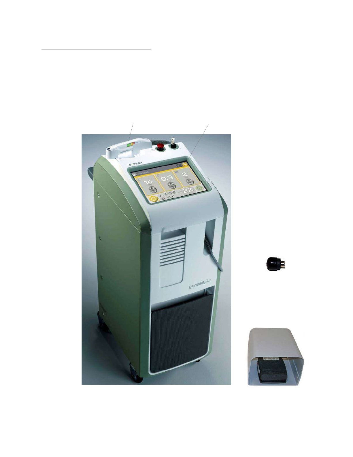
System Console
The system console houses the touchscreen control panel, the main power keyswitch, emer-
gency off switch, control electronics, the 1064 nm laser umbilical with handpiece, the laser
source with associated optics and power supply. The touchscreen control panel allows you to
select treatment settings.
NOTE
To ensure proper air circulation, the console must be positioned at
least 20 centimeters (8 inches) from walls, furniture or other equip-
ment.
Footswitch
The footswitch activates the treatment beam when the system is in READY mode.
Remote Interlock Plug
The system is equipped with a remote interlock plug which, when wired to an external door
switch, shuts down the system power if the treatment room door is opened or the interlock plug
is removed. To resume treatment, close the treatment room door or reinsert the remote inter-
lock plug, and restart the system using the keyswitch.
Use of an external door switch is optional; however, the remote interlock plug must be inserted
into the interlock receptacle at all times for proper operation.
NOTE
Refer to the Maintenance section of this operator manual for
instructions on connecting an external door switch to the remote
interlock plug.
Handpiece
The handpiece delivers laser energy from the system console to the treatment site. An inte-
grated temperature sensor and LED temperature indicators enable thermal monitoring of the
target tissue. A working distance beam ensures proper positioning of the handpiece when cen-
tered within the aiming beam.