I.B. 48008
Page 4
Effective 11/97
MarkV Controller Functions (Cont.)
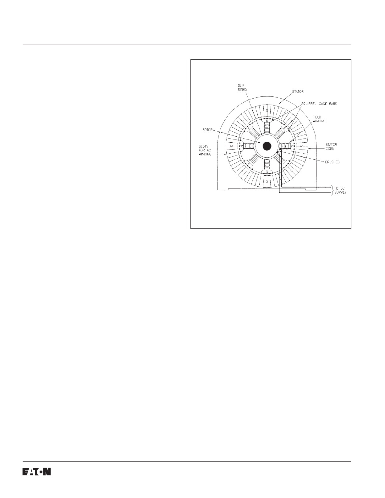
The SCR field power supply QA1, QB1, QC1, QA2, QB2,
andQC2suppliesvoltage(125 or 250VDC) and current to
the motor field. The power supply comes in three sizes,
50,100,or200amperesDC.
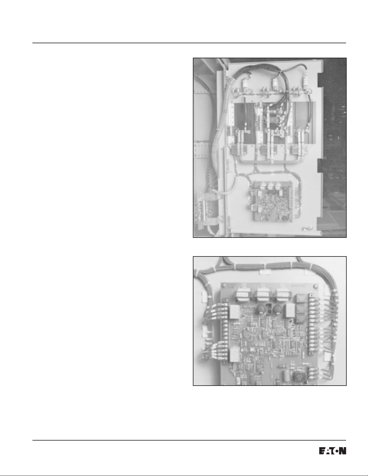
The printed circuit board provides gating signals for the
starting and discharge circuit and protective functions as
well as the SCR power supply.
Thefield power transformer must have either a 120or 240
volt three-phase AC secondary. A 120 volt AC secondary
is required for the 125VDC system. A supply of 240 volts
AC is required for the 250VDC system. It may be con-
nected wye or delta. Do not ground the system. The
transformer is sized KVA = .17 x rated amps DC @ 125
volts DC or KVA = .34 x rated amps DC @ 250 volts DC.
Currenttransformers arefurnished inthemotorstarter
(controller) to supply current to protective relays and
various meters in direct proportion to the line current.
CONTROLLEROPERATION
Figure 4 shows the field power supply controller in con-
junction with the motor controller for a synchronous motor
starter. Note that the connection to the field supply
transformer is between the contactor (M) and the IQ
component so that the current transformers sense motor
stator current only.
The field power supply controller consists of three types of
circuits, one each dedicated to (1) field power, (2) control,
and (3) motor starting. The six thyristors (SCR’s), QA1
throughQC2,arethemaincomponentsofthefield power
circuit. The control circuit controls the starting circuit and
the output of the field power circuit.
A motor start sequence is initiated by closing the line
contactor (M). This results in the motor stator and the
solid-statefieldpowersupply being energized.
On start-up, three-phase voltage signals are supplied to
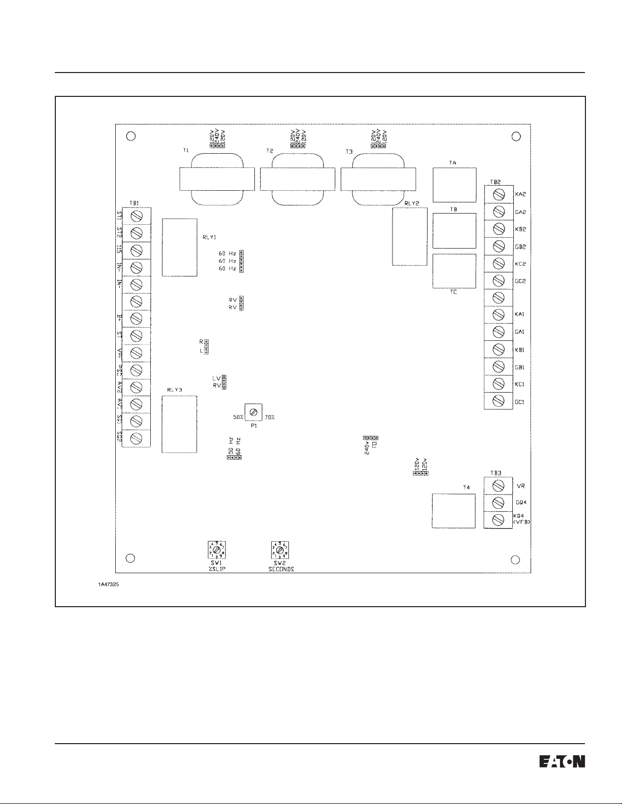
terminals KA2, KB2, and KC2. The open-fuse detection
circuit requires about 100 milliseconds to determine that
all voltages are present. It then causes RLY1 to close the
circuitbetweenterminals ST1 and ST2 onTB1 (Figure 5).
The light emitting diode, LED1 is lit. If any fuse opens
and voltage is lost at terminals KA2, KB2, or KC2, RLY1
will drop out to open the control circuit.
RLY1andRLY3maypulse open andclosedduringcertain
types of faults causing the interposing relay “MX” to drop
out,insuring that the“M”contactor hasdroppedout.SYTR
remainsenergizeduntil “M”dropsout.
The motor starter, being energized, causes the motor field
to generate an output voltage at the instantaneous slip
frequency of the motor. This voltage is controlled by the
independentlyoperatingthyristor-controlled startingcircuit
D1-Q4.
The voltage across the field starting and discharge
resistor (S/D RES) is monitored during the starting
sequencetodeterminetheinstantaneousslipofthemotor.
A motor slip condition of less than 75% (more than 25%
speed) must be reached within the preset time (rotary
switch SW2), ranging from 0 to 9 seconds, or a stalled
rotorcondition will be indicated by the incomplete-se-
quencerelay(RLY3)being energized.
As the motor continues to accelerate and the motor slip
frequency becomes less than the level established by the
setting of rotary switch SW1 (0-9%), the gate drives to the
field power supply thyristors activate and the soft turn-on
circuit begins to apply DC voltage to the motor field. If the
motor does not synchronize, Q4 is gated on. At the same
time gating to QA1 - QC2 is inhibited until Q4 stops
conducting.
Once again QA1-QC2 is gated on, applying voltage to the
motor field. This process is repeated until the motor
synchronizes or until a fixed time in the range of 2.5 to 3.5
secondselapses.
Should the motor continue to slip poles after the 2.5 to 3.5
second period has elapsed, as indicated by the starting
circuit thyristor (Q4) continuing to conduct, the incom-
plete-sequencerelay(RLY3)will be energizedindicatinga
failure to synchronize.
If the motor fails to reach the expected slip frequency
within 34 or 40 seconds from the beginning of the start
sequence,the timeout (TO)function will operateand the
incomplete-sequencerelay(RLY3) willagainbeenergized
if this option is chosen (by inserting jumper TO). See
OPTIONS onPage 6.
Whenmotor synchronizationisbeing established,the
output voltage is sensed and regulation of the field voltage
isaccomplishedbyappropriatecontrolof the gating
patternstothe field power supply thyristors QA1-QC2.