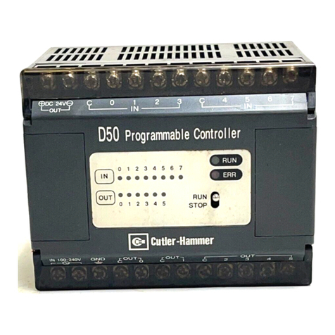
Cutler-Hammer EATON PanelMate ControlNet User manual

Eaton Corporation
Cutler-Hammer Group
811 Greencrest Drive
Columbus, OH 43081
PanelMate ControlNet
CommunicationDriver
Manual

The information contained in this manual is the property of Eaton Corporation. Information in this
manual is subject to change without notice and does not represent a commitment on the part of Eaton
Corporation. Permission is granted to duplicate this material without modification only for your use or
the internal use of other members of your company or your agents to assist you in the use and
servicing of products purchased from Eaton’s Cutler-Hammer Group. No permission is granted to
modify this material or include this material in a compilation.
Any Cutler-Hammer software described in this manual is furnished under a license agreement. The
software may be used or copied only in accordance with the terms of the agreement. It is against the law
to copy the software on any medium except as specifically allowed in the agreement.
RESTRICTED RIGHTS LEGEND
Use, duplication, or disclosure by the Government is subject to restrictions set forth in paragraph
(b)(3)(B) of the Rights in Technical Data and Computer Software clause of DAR 7-104.9(a).
Contractor/Manufacturer is Eaton Corporation’s Cutler-Hammer Group, 811 Greencrest Drive,
Columbus, OH 43081.
TRADEMARKS
PanelMate is a registered trademark of Eaton’s Cutler-Hammer Group.
DOS, Microsoft, and Windows are registered trademarks of Microsoft Corporation.
Commercial names of products from other manufacturers or developers that appear in this manual are
registered or unregistered trademarks of those respective manufacturers or developers, which have
expressed neither approval nor disapproval of Eaton’s Cutler-Hammer Group products.
Copyright Eaton Corporation, 2001. All rights reserved.
Printed in the United States of America.
P/N 01-00484-00

Table of Contents i
Table of Contents
Preface...................................................................................................................................................................P-I
About this Manual......................................................................................................................................P-II
Purpose......................................................................................................................................................P-II
What’s Inside...........................................................................................................................................P-II
Support Services.........................................................................................................................................P-III
Chapter 1: Introduction.......................................................................................................................................1-1
Driver Installation..........................................................................................................................................1-2
Chapter 2: ControlNet Interface Module.........................................................................................................2-1
Hardware Layout...........................................................................................................................................2-2
Address Settings..........................................................................................................................................2-3
LED Indicators...............................................................................................................................................2-4
Net Status...................................................................................................................................................2-4
ControlNet Interface Status.....................................................................................................................2-4
Channel Status..........................................................................................................................................2-4
Connectors.................................................................................................................................................2-5
Chapter 3: Connectivity......................................................................................................................................3-1
Supported Messaging..................................................................................................................................3-2
Network Connection.....................................................................................................................................3-2
Network Termination................................................................................................................................3-2
Connectivity Options...................................................................................................................................3-3
One Operator Station to One PLC..........................................................................................................3-3
Multiple Stations to Multiple PLCs........................................................................................................3-3
PLC Modules.................................................................................................................................................3-4
Operator Station Connection to ControlNet using the ControlNet Interface Module...................3-4
Wiring Guidelines ..........................................................................................................................................3-4
Chapter 4: Memory Addressing and Communications to Allen-Bradley PLC-5 Using DF1 (PCCC)
Messaging .............................................................................................................................................................4-1
PCCC Memory Addressing.........................................................................................................................4-2
General Format...........................................................................................................................................4-2
I/O Format..................................................................................................................................................4-6
Status Format.............................................................................................................................................4-6
Memory Addressing Examples...............................................................................................................4-7
Chapter 5: Memory Addressing and Communications to the Allen-Bradley ControlLogix Using
Control Information Protocol (CIP) Messaging.............................................................................................5-1
CIP References ...............................................................................................................................................5-2
ControlNet Messaging..................................................................................................................................5-3
ControlLogix Addressing.............................................................................................................................5-3
ControlLogix Addressing Using PLC-5 or SLC Address Syntax............................................................5-4
Controller Tags versus Program Tags........................................................................................................5-5
CIP Memory Addressing..............................................................................................................................5-5
Appendix A: Error Codes...................................................................................................................................A-1

ii PanelMate ControlNet Communication Driver Manual
ControlNet Interface Peer Error codes......................................................................................................A-2
System Errors............................................................................................................................................A-2
Local Errors...............................................................................................................................................A-3
Index.........................................................................................................................................................................I-1

Preface I
Preface
Welcome to Cutler-Hammer’s PanelMate ControlNet Communication Driver Manual. This chapter
gives a brief overview of this manual, and provides information on Support Services.

II PanelMate ControlNet Communication Driver Manual
About this Manual
Purpose
This manual describes how to use your Operator Station with ControlNet.
What’s Inside
This manual is organized in the following way:
Preface
Chapter 1: Introduction, describes the ControlNet driver installation.
Chapter 2: ControlNet Interface Module, describes the hardware layout of the ControlNet
Module, as well as a description of the LED indicators and their behaviors.
Chapter 3: Connectivity, describes supported messaging, how the ControlNet module
connects to the network, the connectivity options, how to configure the PLC Name
and Port Table in PanelMate software, and wiring guidelines.
Chapter 4: Memory Addressing and Communications to the Allen-Bradley PLC-5 Using DF1
(PCCC) Messaging, describes PCCC references, memory addressing for the PLC-5,
and monitored I/O.
Chapter 5 Memory Addressing and Communications to the Allen-Bradley ControlLogix
Using Control Information Protocol (CIP) Messaging, describes CIP references
and memory addressing for ControlLogix PLCs.
Appendix A: Error Codes, describes ControlNet Peer Error Codes.
Index Alphabetical listing of important names, subjects, and titles found within this
manual, with their page numbers.

Preface III
Support Services
It is Cutler-Hammer’s goal to ensure your greatest possible satisfaction with the operation of our
products. We are dedicated to providing fast, friendly, and accurate assistance. That is why we offer
you so many ways to get the support you need. Whether it’s by phone, fax, modem, or mail, you can
access Cutler-Hammer support information24 hours a day, seven days a week. Our wide range of
services include:
Technical Support VOICE 1-800-809-2772
FAX 614-882-0417
EMAIL [email protected]
If you are in the U.S. or Canada, you can take advantage of our toll-free line for technical assistance
with hardware and software product selection, system design and installation, and system debugging
and diagnostics. Technical support engineers are available for calls during regular business hours
(8 am - 5:30 pm EST) by calling 1-800-809-2772. International calls can be made to either the Tech Line at
1-800-809-2772 (toll call) or the Cutler-Hammer main business line at 614-882-3282. You can contact our
technical support engineers by faxing your support requests directly to the Advanced Product Support
Center (APSC) located in Columbus, Ohio at 614-882-0417. You can also contact our technical support
Emergency Technical Support VOICE 1-800-809-2772
Because machines do not run on a nine-to-five schedule, we offer emergency after-hours technical
support. A technical support engineer can be paged for emergencies involving plant down situations or
safety issues. Emergency support calls are automatically routed directly to our answering service
after-hours (5:30 pm - 8 am EST) and weekends. For emergency technical support, call 1-800-809-2772.
Note that the Emergency Technical Support phone number does not currently support product repairs
or shipping outside normal business hours.
Information Fax-Back Service FAX 614-899-5323
The latest Cutler-Hammer product information, specifications, technical notes and company news is
available to you via fax through our direct document request service at 614-899-5323. Using a touch-
tone phone, you can select any of the info faxes from our automated product literature and technical
document library, punch in a fax number and receive the information immediately.
If you have Internet capabilities, you also have access to technical support via our website at
http://www.cutlerhammer.eaton.com/automation. The website includes technical notes, frequently
asked questions, release notes, and other technical documentation. This direct technical support
connection also offers you the ability to request assistance and exchange software files electronically.
Bulletin Board Service MODEM 614-899-5209
Parameters: 8 data bits, 1 stop bit, parity none, 9600-28.8K baud
If you have modem access, you can dial in directly to our electronic bulletin board service for the latest
product and company information. File sharing, product software downloads and our user message
service are just a few of the things you will find online at 614-899-5209.

IV PanelMate ControlNet Communication Driver Manual
Software Registration FAX 614-899-4141
EMAIL [email protected]
Register your software and receive free information updates regarding Cutler-Hammer products.
Information will include details of software modificatioins, product enhancements, and reduced-price
software upgrades. Registering your software also gives you access to Technical Support. You can
register your software by using the registration form included with the software kit.
If you have Internet capabilities, you can register your software via our website at
http://www.cutlerhammer.eaton.com/automation. Select “Tech Support” then “Automation Update
Service”. Go to the Software Registration Form, fill it in and then submit the form.
Repair and Upgrade Service VOICE 614-882-3282 ext. 7601
FAX 614-882-3414
Our well-equipped Customer Service department is ready to assist you with repairs, upgrades, and
spare parts services. If a situation arises where one of these services is needed, just call 614-882-3282
x7601 or fax 614-882-3414.
Customer Support Center VOICE 1-800-356-1243
FAX 1-800-752-8602
Authorized Cutler-Hammer distributors and Cutler-Hammer sales offices can get assistance for
Cutler-Hammer standard and component product lines through the Customer Support Center. Call
the Customer Support Center for the following assistance:
1. To place an order.
2. Stock availability, proof of shipment.
3. Expedite an existing order.
4. Product assistance and product price information.
5. Product returns other than warranty returns.
6. Information on local distributors or sales offices.
Address Eaton Corporation
Cutler-Hammer Group
811 Greencrest Drive
Columbus, OH 43081

Chapter 1: Introduction 1-1
Introduction
This chapter discusses:
•Driver installation
1

1-2PanelMate ControlNet Communication Driver Manual
Driver Installation
The Driver Software Kit contains a CD-ROM.
Caution: Before installing the drivers, make sure that the PanelMate Configuration software is not
already running.
To install the drivers from the CD-ROM, select the Install Software option and then Install Drivers.
From the dialog box, select the ControlNet driver you wish to install and then press the OKbutton.

Chapter 2: ControlNet Interface Module 2-1
ControlNet Interface Module
This chapter discusses:
•The Hardware Layout
•Address Settings
•LED Indicators
2

2-2PanelMate ControlNet Communication Driver Manual
Hardware Layout
Below is a graphic representation of the end view of the ControlNet interface card.
J3 J2 SW1
4 2
3 1
The top set of stacked LED's are used to monitor UCS and network specific status. The bottom set of
stacked LED's are used to monitor redundant ControlNet channel status. See the table below for a more
detailed description of each component.
Item Description
1ControlNet Interface Status
2Network Specific Status
3Channel B Status
4Channel A Status
J2 ControlNet Channel A BNC Connector
J3 ControlNet Channel B BNC Connector
SW1 ControlNet Addressing Switches
See following table for address settings.

Chapter 2: ControlNet Interface Module 2-3
Address Settings
Address Address
1
2
3
4
5
6
7
8
1
2
3
4
5
6
7
8
0
0
0
0
0
0
0
0
0
50
0
0
1
1
0
0
1
0
1
0
0
0
0
0
0
0
1
51
0
0
1
1
0
0
1
1
2
0
0
0
0
0
0
1
0
52
0
0
1
1
0
1
0
0
3
0
0
0
0
0
0
1
1
53
0
0
1
1
0
1
0
1
4
0
0
0
0
0
1
0
0
54
0
0
1
1
0
1
1
0
5
0
0
0
0
0
1
0
1
55
0
0
1
1
0
1
1
1
6
0
0
0
0
0
1
1
0
56
0
0
1
1
1
0
0
0
7
0
0
0
0
0
1
1
1
57
0
0
1
1
1
0
0
1
8
0
0
0
0
1
0
0
0
58
0
0
1
1
1
0
1
0
9
0
0
0
0
1
0
0
1
59
0
0
1
1
1
0
1
1
10
0
0
0
0
1
0
1
0
60
0
0
1
1
1
1
0
0
11
0
0
0
0
1
0
1
1
61
0
0
1
1
1
1
0
1
12
0
0
0
0
1
1
0
0
62
0
0
1
1
1
1
1
0
13
0
0
0
0
1
1
0
1
63
0
0
1
1
1
1
1
1
14
0
0
0
0
1
1
1
0
64
0
1
0
0
0
0
0
0
15
0
0
0
0
1
1
1
1
65
0
1
0
0
0
0
0
1
16
0
0
0
1
0
0
0
0
66
0
1
0
0
0
0
1
0
17
0
0
0
1
0
0
0
1
67
0
1
0
0
0
0
1
1
18
0
0
0
1
0
0
1
0
68
0
1
0
0
0
1
0
0
19
0
0
0
1
0
0
1
1
69
0
1
0
0
0
1
0
1
20
0
0
0
1
0
1
0
0
70
0
1
0
0
0
1
1
0
21
0
0
0
1
0
1
0
1
71
0
1
0
0
0
1
1
1
22
0
0
0
1
0
1
1
0
72
0
1
0
0
1
0
0
0
23
0
0
0
1
0
1
1
1
73
0
1
0
0
1
0
0
1
24
0
0
0
1
1
0
0
0
74
0
1
0
0
1
0
1
0
25
0
0
0
1
1
0
0
1
75
0
1
0
0
1
0
1
1
26
0
0
0
1
1
0
1
0
76
0
1
0
0
1
1
0
0
27
0
0
0
1
1
0
1
1
77
0
1
0
0
1
1
0
1
28
0
0
0
1
1
1
0
0
78
0
1
0
0
1
1
1
0
29
0
0
0
1
1
1
0
1
79
0
1
0
0
1
1
1
1
30
0
0
0
1
1
1
1
0
80
0
1
0
1
0
0
0
0
31
0
0
0
1
1
1
1
1
81
0
1
0
1
0
0
0
1
32
0
0
1
0
0
0
0
0
82
0
1
0
1
0
0
1
0
33
0
0
1
0
0
0
0
1
83
0
1
0
1
0
0
1
1
34
0
0
1
0
0
0
1
0
84
0
1
0
1
0
1
0
0
35
0
0
1
0
0
0
1
1
85
0
1
0
1
0
1
0
1
36
0
0
1
0
0
1
0
0
86
0
1
0
1
0
1
1
0
37
0
0
1
0
0
1
0
1
87
0
1
0
1
0
1
1
1
38
0
0
1
0
0
1
1
0
88
0
1
0
1
1
0
0
0
39
0
0
1
0
0
1
1
1
89
0
1
0
1
1
0
0
1
40
0
0
1
0
1
0
0
0
90
0
1
0
1
1
0
1
0
41
0
0
1
0
1
0
0
1
91
0
1
0
1
1
0
1
1
42
0
0
1
0
1
0
1
0
92
0
1
0
1
1
1
0
0
43
0
0
1
0
1
0
1
1
93
0
1
0
1
1
1
0
1
44
0
0
1
0
1
1
0
0
94
0
1
0
1
1
1
1
0
45
0
0
1
0
1
1
0
1
95
0
1
0
1
1
1
1
1
46
0
0
1
0
1
1
1
0
96
0
1
1
0
0
0
0
0
47
0
0
1
0
1
1
1
1
97
0
1
1
0
0
0
0
1
48
0
0
1
1
0
0
0
0
98
0
1
1
0
0
0
1
0
49
0
0
1
1
0
0
0
1
99
0
1
1
0
0
0
1
1
Switch Position Switch Position

2-4PanelMate ControlNet Communication Driver Manual
LED Indicators
Net Status (Item 2)
The Network Specific LED is the upper-right LED on the ControlNet interface card. See page 2 for a side
view of the card. The following table describes the behavior of the Network Specific LED:
LED State Network Status
Off Network interface offline/No network power
Flashing Red I/O Connection(s) in timed-out state or other Recoverable Fault.
Flashing Green Device is online, but has no running connections
Solid Red Unrecoverable Fault
Solid Green Online with established connections
Flashing Green/Red Self-test for A-B devices
ControlNet Interface Status (Item 1)
The ControlNet Interface status LED is the lower-right LED on the ControlNet interface card. See page 2
for a side view of the card. The following table describes the behavior of the UCS status LED.
LED State Status
Off No power
Solid Red Hardware error
Flashing Red Recoverable configuration fault
(Invalid firmware, OEM data, or Personality Block)
Flashing Green No errors
Solid Green No errors
Amber Configuration mode
Channel Status
The Channel Status LEDs are the left-most stacked set of LEDs on the on the ControlNet interface card.
See page 2 for a side view of the card. They are read together when their states change synchronously
to one another.
States Network Status
Off Network interface offline.
Solid Red Network faulted state or other recoverable fault
Alternating Red/Green Network ASIC self test
Alternating Red/Off Incorrect node configuration.
Check ControlNet parameters or node address.
The Channel StatusLEDs are read independently when their states change asynchronous to one
another:
States Network Status
Off Network channel disabled. Redundant Cable operation disabled.
Solid Green Online normal operation.
Flashing Red/Off Media fault or no other nodes present.
Check for broken cables, bad connectors, etc.
Flashing Green/Off Device is online, but is encountering temporary errors. Check
termination and cables.
Flashing Green/Red Incorrect network configuration.

Chapter 2: ControlNet Interface Module 2-5
Connectors
The Channel A and Channel B connectors (J2 and J3 respectively,) on the ControlNet interface card,
provide redundant coax media connections to ControlNet using standard BNC female connectors. See
page 2for a side view of the card.

2-6PanelMate ControlNet Communication Driver Manual

Chapter 3: Connectivity 3-1
Connectivity
This chapter discusses:
•Supported Messaging
•Network Connection
•Connectivity Options
•PLC Modules
•Wiring Guidelines
3

3-2PanelMate ControlNet Communication Driver Manual
Supported Messaging
The Operator Station with the ControlNet Interface Module supports PCCC and CIP unscheduled
messaging.
Note: PanelMate does not support scheduled messaging.
Network Connection
The figure below shows the rear of a PanelMate Power Pro Series unit. To connect the operator station
to the ControlNet network:
1. Install a "passive Tee” (Tee and drop cable are combined,) connector [1] on the network cable [2].
2. Run a drop cable [3] from the Tee connector to the BNC connector [4] on the ControlNet Module
[5].
Network Termination
If the Operator Station is the last node (at the end of) the network, install a 75 Ωterminating resistor in
the unused plug of the Tee connector.

Chapter 3: Connectivity 3-3
Connectivity Options
One Operator Station to One PLC
Connecting to ControlNet using the ControlNet Interface Card
Multiple Stations to Multiple PLCs

3-4PanelMate ControlNet Communication Driver Manual
PLC Modules
Operator Station Connection to ControlNet using the ControlNet
Interface Module
Configure the following setup in the PLC Name and Port Table.
Field Selection Comments
Port I/O Selects communications card.
Device Use ControlNet ControlNet Peer
Local ID N/A
Data Bits N/A
Stop Bits N/A
Parity N/A
Baud Rate N/A
Electrical N/A
Name Use a six-character name. (alphanumeric or underscore)
Port I/O Name assigned to the PLC by the user
Model Set to match the A-B PLC model type. (Used for range
checking in addressing)
Remote ID Must match the Processor ControlNet Node Number.
Notes:
•Do not duplicate node numbers on the network.
•The Operator Station ID must not match another used number on the network.
Wiring Guidelines
Consult the Allen-Bradley ControlNet publications for details on wiring guidelines.
Table of contents
Other Cutler-Hammer Controllers manuals
Popular Controllers manuals by other brands

Samwontech
Samwontech TEMP2020 series Operation manual

Herz
Herz 7708 Series datasheet

Mitsubishi Electric
Mitsubishi Electric MELDAS MDS-R Series Specifications and Instruction Manual

Halma
Halma ALICAT SCIENTIFIC PC quick start guide

Kikusui
Kikusui PFX2532 Operation manual

LSIS
LSIS LSLV-S100 Series Operation manual