CY MODEL Katana S 40 User manual

Before commencingassembly,please readthese instructionsthoroughly.
SAFETY PRECAUTIONS
This radiocontrol modelis nota toy!
lFirst-time buildersshould seekadvice frompeople havingbuilding
experience inorder toassemble themodel correctlyand toproduce
its performanceto fullextent. ,
lAssemble thiskit onlyin placesout ofchildrens reach!
lTakeenough safetyprecautions priorto operatingthis model.
,
You areresponsible forthis models assemblyand safeoperation!
lAlways keepthis instructionmanual readyat handfor quick
reference,even aftercompleting theassembly.
lCould causeserious injuryor evendeath
SPECIFICATION
Wing Span:1350 mm (53.1 in)
2
Wing Area:35.7 dm (553.5sq.in)
Total Length: 1370 mm (53.9 in)
Engine : 2c 0.40 cu in
Motor : Outrunner brushless motor
Radio : 4 channels ,5 servos
Katana S 40

22
REQUIRED FOR OPERATION (Purchase separately)REQUIRED FOR OPERATION (Purchase separately)
TOOLS REQUIRED ( Purchase separately)TOOLS REQUIRED ( Purchase separately)
BEFOREYOU BEGINBEFOREYOU BEGIN
Sharp Hobby Knife Phillips Screw Driver Awl
Needle Nose Pliers Wire Cutters Scissors
Read through the manual before you begin ,so you will have an overall idea of what to do.
Check all parts .if you find any defective or missing parts .contact your local dealer.
Symbols used throughout this instruction manual,comprise.
11
22
33
.
.
.
Warning!
£¡
Cut off shaded portion.
Ensure smooth non-binding
movement while assembling.
Must be purchased
separately!
Pay close attention
here!
Drill holes with the specified
Diameter(here:2mm)
2mm
Assemble left and right
Sides the same way.
Apply instant glue
(CA glue,super glue).
Apply epoxy glue.
BA
Cut off excess.
!
Do not overlook this symbol.
11
Aminimum 4channel radio for airplanes (with 5servos).
And dry batteries.
CAUTION: Only use a minimum 4channel radio for
airplanes! (No other radio may be used!)
!
12 AA-size Batteries
Aminimum 4 channel
transmitter for airplanes.
22
For handing the radio properly.refer to its instruction manual.
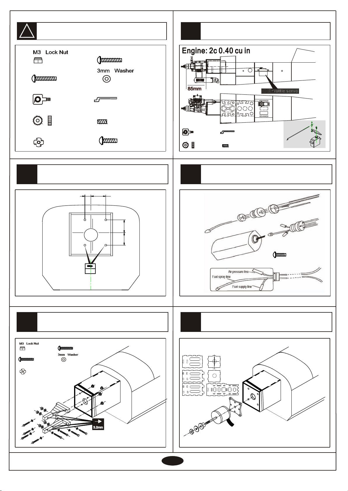
Engine and Muffler
Muffler Glow plug
33
Purchase a propeller that
will match your engine
44
Silicone Tube Fuel Filter
55
required for engine starting Glow engine fuel only.
WARNING: Normal gasoline cannot
be used with glow engines.
!
Fuel Pump Plug Wrench
33
Glue
66
Instant glue Epoxy Glue
33
Other equipment for enhancing
airplane operation & perormance
77
12V Battery (for starter)
Engine Starter
Propeller splinner
MA
Outrunner brushless motor
2c 0.40 cu in
odel irplane engine
Ignition

!
3
2
Install the aileron
1
5
4
Main wing
33
Install the aileron servo
After cut the film ,
insert the elevator into the slot
Install the elevator
Accessory list for this page.
L
R
2mmX445mm carbon stick2mmX445mm carbon stick
Hinge
BA
Rod adjuster
1.8X85mm Rod
- - - - - - 2- - - - - - 2
- - - - - - 2- - - - - - 2
Horn
- - - - - - 2- - - - - - 2
2X20mm Tp Screw
- - - - - - 4- - - - - - 4
Aileron
servo
- - - - - - 8
22X485mm tube22X485mm tube
Servo lineServo line
Cut the film
Hinge- - - - 4
Rod adjuster
1.8X85mm Rod
- - - - - - 2- - - - - - 2
- - - - - - 2- - - - - - 2
Horn
- - - - - - 2- - - - - - 2
2X20mm Tp Screw
- - - - - - 4- - - - - - 4
Hinge
- - - - - -12- - - - - -12
4x30mm nylon screw
- - - - - - 2
4mm washer
- - - - - - 2
8mm nylon Nut
- - - - 4
BA
BA
put the servo line
into the fuselage
put the servo line
into the fuselage
BA

!
8
710
99
44
6
Accessory list for this page.
Instal the rudder
Horizontal/Vertical tail
Securely glue together
,if coming off during flights.
You lose control of your airplane
which leads to accidents!
AAAA
Install the tail wheel
Hinge - - - - 3
- - - - 1- - - - 1
- - - - 1- - - - 1
2.1mm Collar
2.1mm Nylon Collar
3X3mm Screw
- - - - 1- - - - 1 3X12 Tp screw
- - - - 3- - - - 3
- - - - 1- - - - 1
Fold flection
Diameter
2mm
Install the main landing gear
BA
Horizontal/Vertical tail
- - - - 1- - - - 1
- - - - 1- - - - 1
2.1mm Collar
2.1mm Nylon Collar
3X3mm Screw
- - - - 1- - - - 1 3X12 Tp screw
- - - - 3- - - - 3
- - - - 1- - - - 1
Hinge - - - - 3

!
13
12 15
14
11
55
Accessory list for this page.
Install the main landing gear
Rod adjuster
1.8X170mm Rod
- - - - - - 1- - - - - - 1
- - - - - - 1- - - - - - 1
Horn
- - - - - - 1- - - - - - 1
2X14mm Tp Screw
- - - - - - 2- - - - - - 2
Rod adjuster
- - - - - - 1- - - - - - 1
Horn
- - - - - - 1- - - - - - 1
2X10mm Tp Screw
- - - - - - 2- - - - - - 2
Instal the elevator servo
Rudder
servo
Elevator
servo
Install the engine mount
1.8X170mm Rod
- - - - - - 1- - - - - - 1
Rod adjuster
1.8X1400mm Rod
- - - - - - 1- - - - - - 1
- - - - - - 2- - - - - - 2
Horn
- - - - - - 2- - - - - - 2
2X14mm Tp Screw
- - - - - - 4- - - - - - 4
3X12mm screw
3mm nut
3.2mm Collar
3mm Washer
3X3mm screw
2.3X8mm Tp screw
3X35mm screw
- - - - - - 2
- - - - - - 2
- - - - - - 3
- - - - - - 2
- - - - - - 5
- - - - - - 2
- - - - - - 2
Install the rudder servo
Install the engine mount
1.8X140mm Rod
- - - - - - 1- - - - - - 1
3X12mm screw
3mm nut
3.2mm Collar
3mm Washer
3X3mm screw
2.3X8mm Tp screw
3X35mm screw
- - - - - - 2
- - - - - - 2
- - - - - - 3
- - - - - - 2
- - - - - - 5
- - - - - - 2
- - - - - - 2
1.51.5
1.51.5
BBAA

!
18
17 20
19
66
16
Accessory list for this page.
Install the engine mount
Assembly of the full tank
After confirmingthe
position(see frontof
fuel tank).
Insert and tighten
the screw.
Drill 4 holes and set blind nut in appropriate
position in the firewall before install the engine.
Diameter
(here:4.2mm)
4.2mm
3mm Blind Nut
3X25mm Screw
- - - - 12- - - - 12
- - - - 4- - - - 4
- - - - - - 4- - - - - - 4
3X18mm Screw
- - - - 4- - - - 4
- - - - - - 4- - - - - - 4
3mm Blind Nut
3X25mm Screw
- - - - 12- - - - 12
- - - - 4- - - - 4
- - - - - - 4- - - - - - 4
3X18mm Screw
- - - - 4- - - - 4
- - - - - - 4- - - - - - 4
1.4X430mm Rod
- - - - - - 1- - - - - - 1
Linkage Stopper
2mm Nut
- - - - 1- - - - 1
- - - - 1- - - - 1
3X3mm Screw
- - - - - - 1- - - - - - 1
3X20mm Screw
- - - - 1- - - - 1
3X20mm Screw
- - - - 1- - - - 1
Install the engine
24mm10mm
22.5
22.5
1.4X385mm Rod
- - - - - - 1- - - - - - 1
Linkage Stopper
2mm Nut
- - - - 1- - - - 1
- - - - 1- - - - 1
3X3mm Screw
- - - - - - 1- - - - - - 1
Motor :
Outrunner Brushless motor
The motor must be
purchased separately
Install the motor

!
23
22 25
24
77
21
Accessory list for this page.
Assembly the cowling
Install the canopy
2.3x10mm Tp screw2.3x10mm Tp screw
- - - - - - 4- - - - - - 4
53mm Spinner53mm Spinner
PropellerPropeller
3X12mm Tp screw3X12mm Tp screw
- - - - - - 2- - - - - - 2
2.3x10mm Tp screw2.3x10mm Tp screw
- - - - - - 4- - - - - - 4
3X12mm Tp screw3X12mm Tp screw
- - - - - - 2- - - - - - 2
(Receiver)
(Battery)
Radio Equipment

28
27 29
Side view
ELEVATOR
Adjust the travel of each control surface to the
values in the diagrams.
These values fit general flight capabilities.
Readjust according to your needs and flight level.
Top view
26
AILERON
Adjustment.
Top view
Adjust the travel of each control surface to the
values in the diagrams.
These values fit general flight capabilities.
Readjust according to your needs and flight level.
88
Adjustment.
Never fly before checking the Cg s required position.
In order to obtain the CG specified ,reposition the
receiver and battery.
NEVER fly the model
without well balancing.
Warning!
!
CG
Side view
Rudder
Adjust the travel of each control surface to the
values in the diagrams.
These values fit general flight capabilities.
Readjust according to your needs and flight level.
Top view
90-95mm90-95mm
Adjustment
Side view
45
Adjustment.
45 45
45
45
45
Table of contents
Other CY MODEL Toy manuals
Popular Toy manuals by other brands

DELTA-SPORT
DELTA-SPORT 304683 Instructions for use

Eduard
Eduard T-34/85 Assembly instructions

Align
Align T-Rex 700E Combo instruction manual

Fisher-Price
Fisher-Price PEEK A BLOCKS J5293 instruction sheet

Timeless Wings
Timeless Wings Arsenal VG-70 Assembly guide

Mega Bloks
Mega Bloks Barbie Build'n Play Fairy Treehouse manual

Carrera RC
Carrera RC RC Power 370501042 Assembly and operating instructions

REVELL
REVELL BR 43 manual

PARKZONE
PARKZONE Super Decathlon BL instruction manual

Tamiya
Tamiya Volkswagen Beetle 58383 Assembly manual

Textron
Textron Bell 212 Maintenance manual

Chicco
Chicco Fun Travel CUDDLER & GYM instruction manual