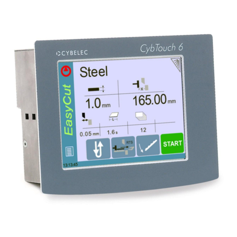
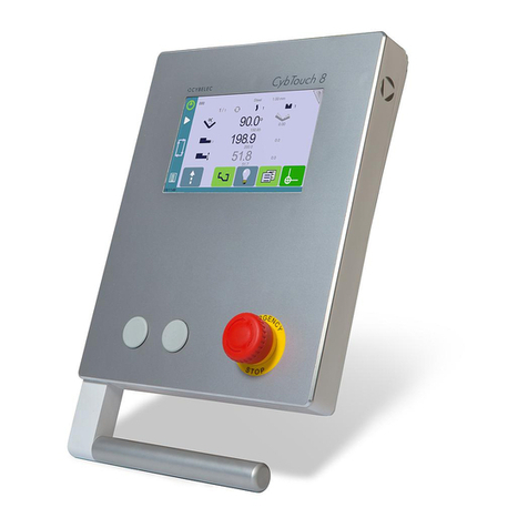
CYBELEC VisiTouch Series User manual

VisiTouch
Series
User Manual
APRIL
2020
V1.1
for Synchronized Press Brakes

User Manual –VisiTouch Series
VisiTouch Series –User Manual
APR.
2020
V1.1
1/45
© 2020 Cybelec
S
.A.
All
Rights R
eserved
Copying, reproduction, modification, distribution, display
or
transmission
of anyof the contents
of
this
manual
for any
purpose
without the
prior
consent of Cybelec
S.A.
is strictly
prohibited.

User Manual –VisiTouch Series
VisiTouch series –User Manual
APR.
2020
V1.1
2/45
Table of Contents
Safety....................................................................................................................................................................6
General Safety ..................................................................................................................................................6
Signs and Icons appearing in this Manual ........................................................................................................7
General warning ...........................................................................................................................................7
Information...................................................................................................................................................7
Settings.........................................................................................................................................................7
Navigation.....................................................................................................................................................7
Getting started with VisiTouch.............................................................................................................................8
Screen Map.......................................................................................................................................................9
Screen Map (continued)................................................................................................................................ 10
General navigation ........................................................................................................................................ 11
Menu Button ............................................................................................................................................. 11
Status Page Zone ....................................................................................................................................... 11
Screen Cleaning ......................................................................................................................................... 11
Status page .................................................................................................................................................... 12
User Preferences ........................................................................................................................................... 12
Language.................................................................................................................................................... 13
Length Units............................................................................................................................................... 13
Force Units................................................................................................................................................. 13
Force / Length Units .................................................................................................................................. 13
Sigma Units................................................................................................................................................ 13
Show axes position values......................................................................................................................... 14
Show bent part .......................................................................................................................................... 14
Materials.................................................................................................................................................... 14
BDC Correction .......................................................................................................................................... 15
Menu horizontal alignment....................................................................................................................... 15
Menu vertical alignment ........................................................................................................................... 15
Clear indexation......................................................................................................................................... 16
USB Explorer.............................................................................................................................................. 16
Beam trace................................................................................................................................................. 16
Auto open beam trace............................................................................................................................... 16
Default retraction...................................................................................................................................... 16
Set Clock .................................................................................................................................................... 16
Touchscreen Calibration............................................................................................................................ 17

User Manual –VisiTouch Series
VisiTouch Series –User Manual
APR.
2020
V1.1
3/45
Offset Pinch Point function........................................................................................................................ 17
Show button up......................................................................................................................................... 17
Show L first ................................................................................................................................................ 17
Beam stop during retractation .................................................................................................................. 17
Manual Axes Movement ............................................................................................................................... 18
Desynchronized Beam............................................................................................................................... 18
Linked axis ................................................................................................................................................. 18
Information Page........................................................................................................................................... 19
USB Transfer.................................................................................................................................................. 20
Precautions................................................................................................................................................ 20
Importing parts from PC program............................................................................................................. 20
Basic Page Description....................................................................................................................................... 21
Bend Numerical Page .................................................................................................................................... 21
Available functions on the Bend Num page .............................................................................................. 21
Quick access tab ........................................................................................................................................ 23
User button tab ......................................................................................................................................... 23
Extra Bending Parameters......................................................................................................................... 24
Copy to All Function ...................................................................................................................................... 28
Tools Management............................................................................................................................................ 29
Punches ......................................................................................................................................................... 29
How to create or modify a punch?............................................................................................................ 30
Dies................................................................................................................................................................ 31
How to create or modify a die?................................................................................................................. 32
Naming Tools................................................................................................................................................. 33
Punches ..................................................................................................................................................... 33
Dies............................................................................................................................................................ 33
Creating a Part Program .................................................................................................................................... 34
TouchProfile Mode........................................................................................................................................ 34
Bend Sequencing........................................................................................................................................... 35
Numerical Mode............................................................................................................................................ 37
L-Alpha Mode ................................................................................................................................................ 38
Bending and Corrections ............................................................................................................................... 39
Semi-Automatic mode............................................................................................................................... 39
Angle Correction (Y axis)............................................................................................................................ 40
Crowning.................................................................................................................................................... 40
Back gauge Correction............................................................................................................................... 41
Managing Programs........................................................................................................................................... 42

User Manual –VisiTouch Series
VisiTouch series –User Manual
APR.
2020
V1.1
4/45
Saving a Program........................................................................................................................................... 42
Creating a Program........................................................................................................................................ 42
Loading a Program......................................................................................................................................... 43
Deleting a Program........................................................................................................................................ 43
Beam Error Messages.................................................................................................................................... 44
Resources .......................................................................................................................................................... 45
Tutorials - Videos........................................................................................................................................... 45

User Manual –VisiTouch Series
VisiTouch Series –User Manual
APR.
2020
V1.1
5/45

User Manual –VisiTouch Series
VisiTouch series –User Manual
APR.
2020
V1.1
6/45
The users must have Read and Understood, but most of all must Respect the directives
described in this manual.
All people coming into contact with the machine on which the numerical control is installed,
whatever their function or whatever state the machine is in (assembly, disassembly, start-up,
production, maintenance, repairs) must have read and understood the requirements
concerning the security and the entirety of the directives of operation described in the
manuals delivered with the machine.
The operator must be properly trained to work with the machine on which the numerical
control is installed. Improper use of the numerical control can cause heavy damage on
equipment and/or injuries to people.
Modification of machine parameters can cause important material damage or lead to
irregular product quality.
Do not expose the numerical control to excessive humidity to avoid any risk of electrocution
and any deterioration of the equipment.
Make sure the numerical control is disconnected from the mains power before carrying out
any cleaning. Do not use liquids based on alcohol or ammoniac.
In case of malfunction of the numerical control, call a technician.
Do not expose the numerical control to direct sun rays or any other heat source.
Do not place the numerical control in the neighbourhood of magnetic equipment such as
transformers, motors or devices which generate interference (welding machines, etc.)
SAFETY
GENERAL SAFETY

User Manual –VisiTouch Series
VisiTouch Series –User Manual
APR.
2020
V1.1
7/45
While using this manual, you will come across the signs and icons represented here below:
they are directly related to the safety and security of persons. Carefully follow this advice and
inform others about it.
This warning sign appears in the manual whenever it is necessary to pay attention to rules,
instructions or advice. The correct sequence of operations is to be followed in order to avoid
damage to the machine. Symbolizes a serious personnel danger.
This warning sign appears in this manual whenever an important information needs to be
taken into consideration. Pay attention to this sign and follow the instructions given.
This sign appears in this manual whenever SETTING INSTRUCTIONS are given. Pay attention to
this sign and follow the sequence of instructions given.
This icon appears in this manual to give navigation information, to give the path to the subject
treated in the chapter.
General warning
Information
Settings
SIGNS AND ICONS APPEARING IN THIS MANUAL
Navigation

User Manual –VisiTouch Series
VisiTouch series –User Manual
APR.
2020
V1.1
8/45
Depending on software evolutions and the press brake controlled by the VisiTouch
(configuration/capabilities), the present manual may not fully correspond to the VisiTouch
that you currently have. However, differences are only minor.
This manual describes all features of
▪VisiTouch19_Press_PS_PC_V1.11.7 and above.
Touchscreens are pressure sensitive.
Do not press down hard on the screen.
Pressing hard on the screen will damage the display. Such damage is not covered by
manufacturer warranty!
Do not use sharp and/or pointed objects (sheet metal, screwdriver, metal pen ball, etc.) to
touch the screen; only use your fingers (with or without gloves on) or a plastic pen. Make sure
that your gloves do not have metal particles encrusted in the fingertips as they may also
damage the screen.
Take a few minutes to practice pressing gently on the screen, you will find that the screen is
very reactive, and it is pleasant to use.
GETTING STARTED WITH VISITOUCH

User Manual –VisiTouch Series
VisiTouch Series –User Manual
APR.
2020
V1.1
9/45
SCREEN MAP
Basic Page Description
Punches
Punches
Dies
Dies
Correction Page
Extra Bending Parameters
TouchProfile Mode
Bend Sequencing
L-Alpha Mode
Bend

User Manual –VisiTouch Series
VisiTouch series –User Manual
APR.
2020
V1.1
10/45
SCREEN MAP (CONTINUED)
Manual Page
Set Clock
User Preferences
Materials
Service Page
Information Page
Backup Page
USB Transfer
Machine Parameters
Logs

User Manual –VisiTouch Series
VisiTouch Series –User Manual
APR.
2020
V1.1
11/45
The Menu button allows you to directly select (jump to) the desired screen. The content
of the menu changes contextually.
Briefly touching the Status pages zone gives access to the Status page. This is really a zone
that is active at any moment from any page.
Touching this zone for more than 2 seconds will activate the Semi-Automatic mode.
To clean the screen while the VisiTouch is on, touch the button.
Use only a damp and smooth cloth with soap or a neutral detergent.
NEVER use solvent, petrol, benzene, alcohols, etc.
GENERAL NAVIGATION
Screen Cleaning button
Add step or
next step
Status
Pages Zone
Menu button
Status Page Zone
Screen Cleaning
Menu Button

User Manual –VisiTouch Series
VisiTouch series –User Manual
APR.
2020
V1.1
12/45
The Status page shows the status of all inputs and outputs and axes positions of the NC.
This feature is very useful during setup or during phone service with a machine installed in
the field.
This page is accessed from anywhere by pressing the Status Pages Zone.
To exit the Status page, press on the arrow on the left.
Axes have specific indicators. Their colour indicates the position of the axis relative to the
tolerance.
Possible states are:
•: Device not active and in the tolerance.
•: Device moving.
•: Device not active and outside of the tolerance.
(Menu Button) → …→ User preference
To exit the User Preference page, touch the button.
STATUS PAGE
A cycle message may
appear indicating the
cycle phase the
machine is executing
Axis status indicator
Beam trace Button
Press arrow to
exit Status Page
USER PREFERENCES

User Manual –VisiTouch Series
VisiTouch Series –User Manual
APR.
2020
V1.1
13/45
To browse through the available languages, simply touch Language on the screen.
Available languages are:
•EN English.
•FI Suomi.
•RU Русский.
•BR Brazil.
•FR Français.
•SL Slovensko.
•CN 中文.
•IT Italiano.
•TR Türkçe.
•CZ Český.
•NL Nederlands.
•TW 台灣.
•DE Deutsch.
•PL Polski.
•ES Español.
•PT Português.
The list of available languages is subject to change and may increase over time.
This parameter allows choosing between mm, inch and none for the length unit to be used
in the VisiTouch.
When none is selected, the units used are millimetres.
This parameter allows choosing between ton, kN and tons for the force unit to be used in
the VisiTouch.
This parameter allows choosing between ton/m, kN/m and tons/ft for the force/length unit
to be used in the VisiTouch.
This parameter allows choosing between kg/mm2, N/mm2 and psi (*1000) for the sigma
unit to be used in the VisiTouch.
Language
Length Units
Force Units
Force / Length
Units
Sigma Units

User Manual –VisiTouch Series
VisiTouch series –User Manual
APR.
2020
V1.1
14/45
This function will display the axes positions on the Bend Numerical Page.
•When set to no, the position of axes Y1, X and R is displayed during the beam’s
movements.
•When set to yes1, the positions of the axes (Y1, Y2, X and R) are displayed during
their respective movements.
•When set to yes2, the positions of the axes (Y1, Y2, X and R) are constantly
displayed under their respective set-point values.
This parameter, when activated, lets the operator see the state of the part before and after
the bend in the Bend Sequencing page.
Touching Materials opens the Materials page, where the default characteristics for each
material can be changed, or a new material can be configured.
To be allowed to access the Materials page, a level 2 password is required.
The Materials page displays:
•Material: Selected material (here Steel).
•Default thickness for the material.
•Default sigma: Default sigma for the material (here 45).
•Displayed: If the material will be available to be selected for use (here yes).
Show axes
position values
Show bent part
Materials

User Manual –VisiTouch Series
VisiTouch Series –User Manual
APR.
2020
V1.1
15/45
•Predefined thickn.: Allows defining up to 7 different predefined thicknesses for
the selected material.
•Thickness min/max: Determines the maximum and minimum accepted thickness
for the selected material.
Three predefined default materials are available (steel, stainless steel, aluminium), but
others can be added.
To add a material:
1. Touch Material and select a non-configured material (Mater X) from the list.
2. Enter the new material’s characteristics.
3. Touch the name (Mater X) to display the keyboard and enter the name of the new
material.
This parameter allows the operator to apply a permanent correction to the Bottom Dead
Centre position.
Please note that this correction is always applied and is NOT shown in the
correction page. If you experience big differences from what you expect to get,
maybe check the value of this parameter.
This parameter allows the operator to choose on which side –Left of Right –he prefers to
have the side bar containing the Menu Button .
This parameter allows the operator to choose if he prefers to have the menu displayed at
the Bottom or at the Top of the screen when he presses the Menu Button .
BDC Correction
Menu horizontal
alignment
Menu vertical
alignment

User Manual –VisiTouch Series
VisiTouch series –User Manual
APR.
2020
V1.1
16/45
When activated, this function clears the index and the machine will search for them, as
it does when turning the power on, allowing the operator to re-index its machine without
turning it off.
When this parameter is set to yes, it is possible to browse the USB key from the USB
transfer screen (see USB Transfer).
A USB key must be inserted.
Preferably use a specific USB key for transferring parts and VisiTouch Data
instead to use a generic memory stick full of data programs that are not relevant
for the numerical control.
When this parameter is set to yes, this small button is displayed on the Status page. By
activating/deactivating it, one can start and stop the recording of beam traces.
When activated, this function will open the beam trace screen automatically at the end of
the recording.
This parameter allows defining the default value displayed in the Extra Bending
Parameters when activating the back-gauge retraction function.
In TouchProfile Mode, when a retraction is necessary, the numerical control will
automatically calculate and activate the function. The calculated value can naturally
be manually modified.
Allows the user to set the time and date on the VisiTouch.
Clear indexation
USB Explorer
Default retraction
Set Clock
Use the up and down
arrows to modify the
selected field
Touch the field you
want to modify
Beam trace
Auto open beam
trace

User Manual –VisiTouch Series
VisiTouch Series –User Manual
APR.
2020
V1.1
17/45
This function allows the calibration of the touch screen.
SETTING INSTRUCTIONS:
Simply follow the instructions on the page to calibrate the touchscreen.
Use your finger or the plastic tip of a pen to calibrate the Touchscreen. Never use
sharp objects as this will damage the screen.
When this parameter is set to yes, the Offset Pinch Point function is available in the Extra
Bending Parameters.
When this parameter is set to yes, the button up is available when the beam is not at
TDC.
Upward command
The beam goes up as long as the button is pressed.
Go to TDC max
The beam goes to TDC max
Go to next TDC
The beam goes to the next TDC. (first to programmed TDC, then
to the TDC max)
This function allows choosing the data entry mode for the back gauge on the Bend
Numerical Page or EasyBend Page. When set to yes, the length of the flange icon is
displayed by default. When set to no, the icon for the position in mm of the back gauge
is displayed.
When set to never, the position of the back gauge is no longer linked to the bending
angle, i.e. the position is never recalculated when the bending angle is modified.
The default value for this preference is never. Note that completely formatting
the machine will reset this preference to its default value.
The mode is not available for graphical parts (see also Set point back
gauge (X axis) / flange length).
When this parameter is set to yes, the down movement of the beam is stopped and the
beam is maintained in closed loop at pinch point during the retraction. The beam cycle will
resume as soon as the back gauge has finished its retraction.
Touchscreen
Calibration
Offset Pinch Point
function
Show button up
Show L first
Beam stop during
retractation

User Manual –VisiTouch Series
VisiTouch series –User Manual
APR.
2020
V1.1
18/45
In the course of setting up a machine, it is sometimes necessary to be able to move the axes
manually, for example when changing the tooling. This can be done on this page.
(Menu Button) → Manual movement
SETTING INSTRUCTIONS:
1. Select the axis that you want to move:
•by selecting the desired axis from the drop down menu.
•by selecting this icon for the crowning axis.
•or for the tool clamping devices (if available).
2. Touch the buttons to move the selected axis.
3. Use the foot switch (Low Speed Down movement) and this button (High
Speed Up) to move the beam.
By selecting a line where the padlock is open , it is possible to select and move (Low Speed
Down movement) Y1 or Y2 only. This is an easy way to return an unsynchronized beam back
to parallel to the table.
Depending on the configuration of the machine, a padlock can be displayed next to the axes
selected. This means that the movements of these axes are interlocked. In a similar fashion
as here above, when the padlock is open , it is possible to select and move a single axis.
MANUAL AXES MOVEMENT
Set here the bending
force that will be applied
to the manual movement
Move beam up (button
hidden if movement
not allowed)
Menu button
Desynchronized
Beam
Drop down menu with
the list of available axis
Linked axis
Table of contents
Other CYBELEC Controllers manuals
Popular Controllers manuals by other brands

TBG
TBG SARS-CoV-2 IgG quick start guide

Morningstar
Morningstar SUNSAVER MPPT SS-MPPT-15L Installation and operation manual

Honeywell
Honeywell S8600B installation instructions

Omron
Omron C500-FZ001 original operation manual

Viessmann
Viessmann Vitotronic 11 CC1E Installation and service instructions

Texas Instruments
Texas Instruments LM5020 manual

Cooper
Cooper McGraw-Edison VR-32 Installation, operation and maintenance instructions

DXT
DXT Eurolite Node IV user manual

Shinko
Shinko JCS-33A instruction manual

Samson
Samson 42-37 Mounting and operating instructions

PERCo
PERCo CT/L-14 Assembly and operation manual

HighPoint
HighPoint RR2720A installation guide