manuals.online logo
Brands
  1. Home
  2. •
  3. Brands
  4. •
  5. CyberData
  6. •
  7. Telephone
  8. •
  9. CyberData 011460 Manual

CyberData 011460 Manual

Quick Reference 931472A © 2018, CyberData Corporation, ALL RIGHTS RESERVED© 2018, CyberData Corporation, ALL RIGHTS RESERVED 931472A Quick Reference
Typical System Installation
Getting Started
• Download the Operations Guide PDF file, from the Downloads tab at the following webpage:
http://www.cyberdata.net/voip/011460/
• Create a plan for the locations of your SIP Weatherproof Keypad Phones.
• WARNING: This product should be installed by a licensed electrician according to all local electrical and building codes.
• WARNING: To prevent injury, this apparatus must be securely attached to the floor/wall in accordance with the installation
instructions.
• WARNING: The PoE connector is intended for intra-building connections only and does not route to the outside plant.
•WARNING: This enclosure is not rated for any AC voltages!
Parts
Parameter Factory Default Setting
IP Addressing DHCP
IP Addressa
a. Default if there is not a DHCP server present.
10.10.10.10
Web Access Username admin
Web Access Password admin
Subnet Maska255.0.0.0
Default Gatewaya10.0.0.1
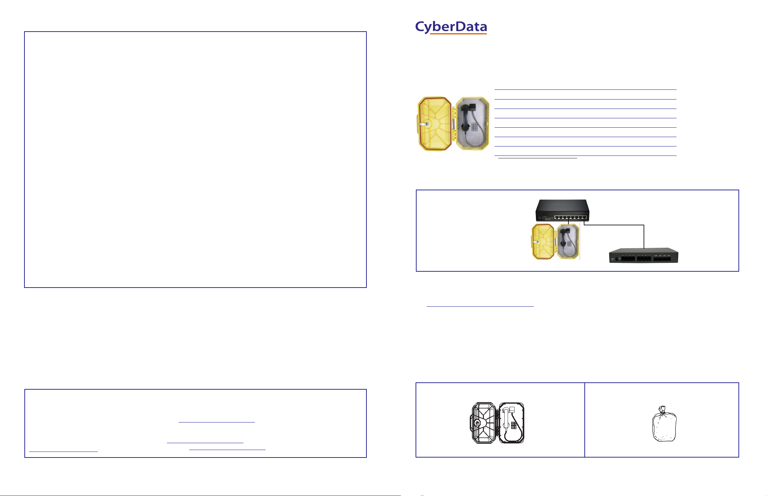
Generic PoE Switch
SIP Weatherproof Keypad Phone IP PBX Server
*More installation and mounting
options are available in the
Operations Guide.
#
*
0
9
7 8
456
1 2 3
(1) SIP Weatherproof Keypad Phone Accessory Kit
Installation
Contacting CyberData
Follow all appropriate electrical codes and use only approved electrical fittings for the installation.
1. Determine if power to operate the device will be provided via the Ethernet or if external power will be required. If external power is
required, install an Auxiliary Power Supply or the equivalent. See the Terminal Block Connections section.
2. To maintain Ingress Protection / NEMA ratings, use appropriately rated hardware and waterproofing techniques.
3. Choose a wall location that is free of obstructions and permits space for conduit runs.
4. Ensure mounting can support 11.8 lbs (5.4kg) and any additional foreseeable load.
If using an auxiliary power supply, ensure it is unplugged during installation to avoid the danger of an accidental shock or
circuit damage.
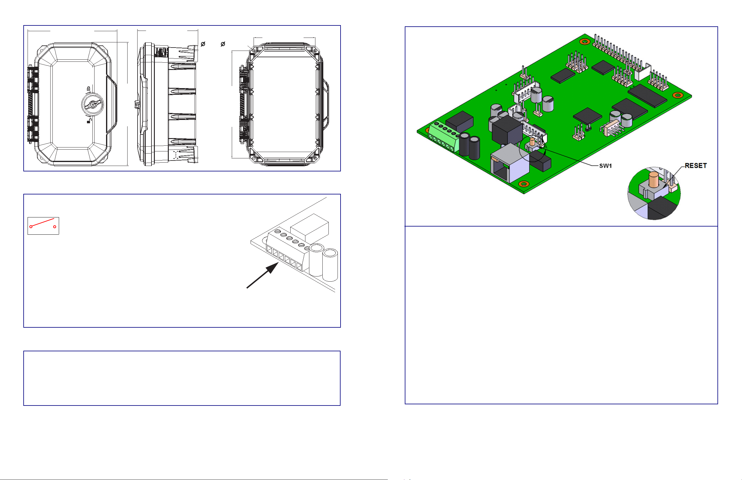
5. Separate the faceplate from the housing by removing the two temporary, factory installed screws.
Note The handset and all electronics are attached to the front plate. The front cover may be separated from the back box by
disconnecting the harness plugs. Be careful when removing the faceplate. The circuit board is on the faceplate.
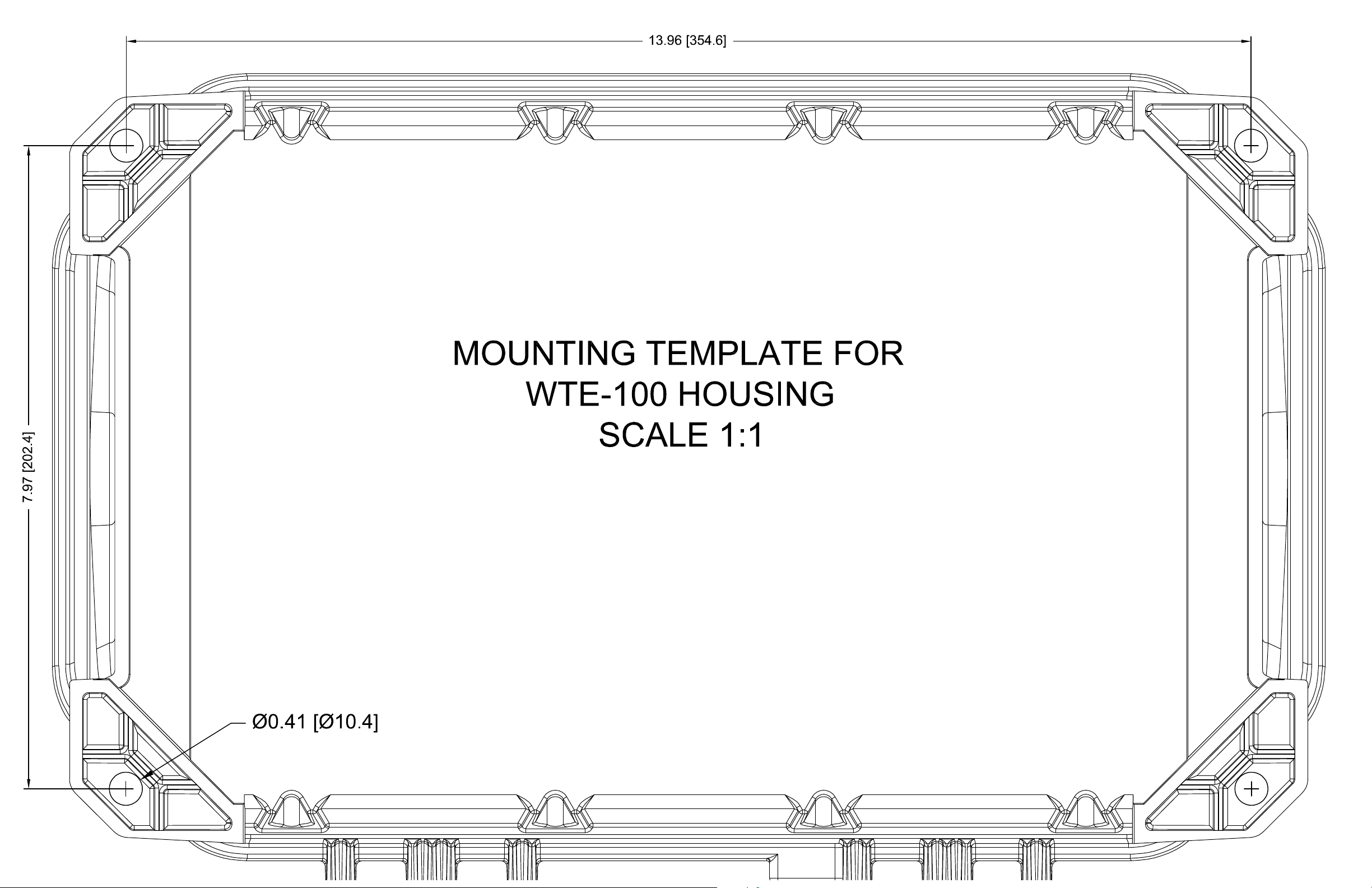
6. Drill or punch cable entrances as required. There are three drill dimples to assist.
7. Use the provided template to locate and drill holes for mounting screws.
8. Use ¼-inch or M8 screws to secure the unit to the wall.
9. Bring the Network cable into the enclosure through the conduit entrance and plug into the RJ-45 connector on the PCBA.
10. If using an alternate power supply connect the supply to the terminal block J9. Before doing so determine if power is supplied over
the Ethernet cable. See the Terminal Block Connections section.
11. Connect the on-board relay if utilized. See the Operations Guide for details.
12. Reconnect the faceplate harness.
13. Ensure all connections are secure.
14. Determine that the device is properly connected by pressing the RESET switch to announce the IP address (see the Reset Test
Function Management (RESET) Switch section). LEDs on the RJ45 connector indicate network connection and activity. See the
Operations Guide for LED details.
15. Replace the faceplate.
16. Set up and configure if changes are required to the default settings.
17. Test the unit by calling to and from another device, preferably a VoIP device. See the Operations Guide for LED details.
Sales: (831) 373-2601 ext. 334
Support: 831-373-2601 ext. 333
Support Website: http://support.cyberdata.net/
RMA Department: (831) 373-2601 ext. 136
RMA Email: [email protected]
RMA Status: http://support.cyberdata.net/
Warranty Information: http://support.cyberdata.net/
Corporate Headquarters
CyberData Corporation
3 Justin Court
Monterey, CA 93940, USA
Phone: 831-373-2601
Fax: 831-373-4193
http://www.cyberdata.net/
The IP Endpoint Company
Installation Quick Reference
SIP Weatherproof Keypad Phone
SIP Compliant
011460
© 2018, CyberData Corporation, ALL RIGHTS RESERVED 931472A Quick Reference Quick Reference 931472A © 2018, CyberData Corporation, ALL RIGHTS RESERVED
Dimensions
Terminal Block Connections
Operation
7.9" [200mm]
11.6" [296mm]
16.1" [409mm]
14.00" [356mm]
8.00" [203mm]
Ø0.41" [Ø10.4mm]
11.6” [296 mm] 7.9” [200 mm]
16.1” [409 mm]
8.0” [203 mm]
14.0” [356 mm]
0.41” [ 10.4 mm]
WIRE IN
Can accept wire range from
16AWGto24AWG
12
Alternate Power Input:
1 = Normally Open Common
2 = Normally Open Contact
Relay Contact:
(0.5 A at 30 VDC for continuous loads)
3 = +24 VDC @ 1000mA
4 = Power Ground
5 = Ringer +
6 = Ringer -
*Contacts 3 and 4 on the terminal block are only for
powering the device from a non-PoE +24 VDC power
source as an alternative to Network PoE power. Use of
these contacts for any other purpose will damage the
device and void the product warranty.
• The SIP Weatherproof Keypad Phone may be set up for either keypad dialing or auto-dialing.
• If the device is configured for keypad dialing, operation is identical to most other single line telephones.
• If the device is configured for auto dialing, lift the handset and press the number assigned to the extension to be dialed.
• Adjust the receiver volume with the switch in the handset.
Note The Operation details are explained in the Operations Guide.
Reset Test Function Management (RESET) Switch
When the device is operational and linked to the network, use the Reset Test Function Management (RESET) switch on the
board (see picture) to announce the device’s IP Address and test that the audio is working. During the IP address announcement,
you will hear the audio test message through the handset receiver.
To announce the device’s current IP address:
1. Press and release the RESET switch (SW1). Hold between two and five seconds.
Note The device will use DHCP to obtain the new IP address (DHCP-assigned address or default to 10.10.10.10 if a DHCP
server is not present).
Note Pressing and holding the RESET switch for longer than five seconds will restore the device to the factory default settings.
To restore the device to factory default settings:
When troubleshooting configuration problems, it is sometimes convenient to restore the device to a known state.
Note Each device is delivered with factory set default values.
To set the factory default settings:
1. Press and hold the RESET switch (SW1) until the device announces it is restoring to factory defaults, then release the reset
switch (Approximately 10 seconds).
Note The device will use DHCP to obtain the new IP address (DHCP-assigned address or default to 10.10.10.10 if a DHCP
server is not present).
Quick Reference 931472A © 2018, CyberData Corporation, ALL RIGHTS RESERVED© 2018, CyberData Corporation, ALL RIGHTS RESERVED 931472A Quick Reference
Note: Before printing this document or the mounting template, check the following:
Make sure that the Paper Size setting of the printer is set to 11x 17.
Make sure that the Page Scaling setting of the printer is set to NONE.
TEMPLATE TESTED AND APPROVED FOR RELEASED ON 2/13/18 BY ANDREW WONG

Other manuals for 011460

1

Other CyberData Telephone manuals

CyberData 011460 User manual

CyberData

CyberData 011460 User manual

CyberData RAL 9002 User manual

CyberData

CyberData RAL 9002 User manual

CyberData DX80 Manual

CyberData

CyberData DX80 Manual

CyberData Cisco DX70 Manual

CyberData

CyberData Cisco DX70 Manual

CyberData 011049 User manual

CyberData

CyberData 011049 User manual

CyberData DX80 Manual

CyberData

CyberData DX80 Manual

Popular Telephone manuals by other brands

V-tech gz5838 user manual

V-tech

V-tech gz5838 user manual

Vlsi VS1000+1003 user manual

Vlsi

Vlsi VS1000+1003 user manual

iPECS LIP-8004D user guide

iPECS

iPECS LIP-8004D user guide

Audiovox Minivox MVX-850 manual

Audiovox

Audiovox Minivox MVX-850 manual

Yealink W52 quick guide

Yealink

Yealink W52 quick guide

Mitel Inter-Tel Axxess Administrator's guide

Mitel

Mitel Inter-Tel Axxess Administrator's guide

Panasonic KX-UT136 user guide

Panasonic

Panasonic KX-UT136 user guide

GE 29115AE1 user guide

GE

GE 29115AE1 user guide

Panasonic KX-T3155A Operation guide

Panasonic

Panasonic KX-T3155A Operation guide

EMPORIA KFT19-UK quick start guide

EMPORIA

EMPORIA KFT19-UK quick start guide

Geemarc AmpliDECT250 user guide

Geemarc

Geemarc AmpliDECT250 user guide

NEC DT310 user guide

NEC

NEC DT310 user guide

Ericsson Dialog 3213 user guide

Ericsson

Ericsson Dialog 3213 user guide

NEC Univerge DT820 user guide

NEC

NEC Univerge DT820 user guide

NEC i-Series Quick reference guide

NEC

NEC i-Series Quick reference guide

D-Link DVC-1000 product manual

D-Link

D-Link DVC-1000 product manual

Polycom soundpoint IP series quick start guide

Polycom

Polycom soundpoint IP series quick start guide

MiTAC N672 Series user manual

MiTAC

MiTAC N672 Series user manual

manuals.online logo
manuals.online logoBrands
  • About & Mission
  • Contact us
  • Privacy Policy
  • Terms and Conditions

Copyright 2025 Manuals.Online. All Rights Reserved.