Cytron Technologies UIC00A User manual

UIC00A
USB ICSP PIC PROGRAMMER
User’s Manual
V1.8
Oct 2009
Information contained in this publication regarding device applications and the like is intended through suggestion only and may
be superseded by updates. It is your responsibility to ensure that your application meets with your specifications. No
representation or warranty is given and no liability is assumed by Cytron Technologies Incorporated with respect to the accuracy
or use of such information, or infringement of patents or other intellectual property rights arising from such use or otherwise. Use
of Cytron Technologies’s products as critical components in life support systems is not authorized except with express written
approval by Cytron Technologies. No licenses are conveyed, implicitly or otherwise, under any intellectual property rights.

ROBOT . HEAD to TOE
Product User’s Manual – UIC00A
Created by Cytron Technologies Sdn. Bhd. – All Right Reserved
Index
1. Introduction and Overview 1
2. PackagingList 2
3. Supported PIC 3
4. Board Layout 5
5. Installation(hardware) 6
5.1 Using UIC00A with application circuit (development board) 6
5.2 Using UIC00A with UIC-S (optional, buy separately) 7
5.2.1 Plugging the microcontroller 8
6. Installation(software) 11
7. GettingStarted 15
7.1 Using PICkit 2 Programmer Software 15
7.2 Using UIC00A 26
7.2.1 Using UIC00A with application circuit (development board) 27
7.2.2 Using UIC00A with UIC-S (optional, buy separately) 29
7.3 Troubleshooting 30
8. Warranty (6 months) 31

ROBOT . HEAD to TOE
Product User’s Manual – UIC00A
Created by Cytron Technologies Sdn. Bhd. – All Rights Reserved 1
1. INTRODUCTION AND OVERVIEW
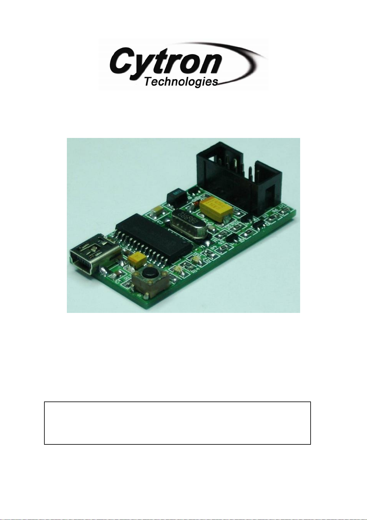
UIC00A offers low cost yet reliable and user friendly PIC USB programmer solutions for
developer, hobbyist and students. It is designed to program popular Flash PIC MCU which
includes PIC12F, PIC16F and PIC18F family. It can also program 16bit PIC MCU. On board
ICSPTM (In Circuit Serial Programming) connector offers flexible method to load program. It
supports on board programming which eliminate the frustration of plug-in and plug-out of
PIC MCU. This also allow user to quickly program and debug the source code while the
target PIC is on the development board. Since USB port is commonly available and widely
used on Laptop and Desktop PC, UIC00A is designed to be plug and play with USB
connection. This programmer obtained it power directly from USB connection, thus NO
external power supply is required, making it a truly portable programmer. This programmer
is ideal for field and general usage. UIC00A offers reliable, high speed programming and free
windows interface software.
It is designed with capabilities and features of:
•Industrial grade PCB with surface mount component to offer small size yet reliable
and quality product.
•Every component is soldered properly and programmer is tested before it is shipped
to customer.
•USB Plug and Play function.
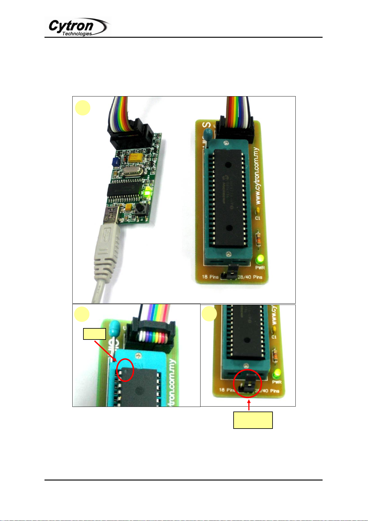
•IDC box header for ICSPTM connection, an IDC cable is included for external on
board programming.
•Windows XP compatible software.
•Compatible with Windows Vista*.
•Auto load program capability.
•Compatible with Microchip’s PICkit 2.
•Optional external power to target PIC should be +5V.
•Small size of 5cm x 2.5cm.
•Powered directly from USB port.
•NO EXTERNAL POWER REQUIRED for UIC00A to function.
•USB 2.0
•Low cost yet reliable solution.
•Suitable for Laptop and Desktop PC.
•Optional socket (UIC-S) to program 18 pins, 28 pins and 40 pins PIC
microcontroller.
*UIC00A has been tested on several editions of Windows Vista. If user found it is not compatible, we will offer
money back guarantee (need to be shipped back within 3 days from receiving date, shipping is not included).
This document explains the method to use UIC00A.

ROBOT . HEAD to TOE
Product User’s Manual – UIC00A
Created by Cytron Technologies Sdn. Bhd. – All Rights Reserved 2
2. PACKAGING LIST
Please check the parts and components according to the packing list. If there are any parts
1. 1 x UIC00A main board
2. 1 x mini USB cable
3. 1 x rainbow cable (programming cable)
4. 1 x Software Installation and User’s Manual CD
5. 1 x UIC-S socket board (optional, buy separately from Cytron website)
1
3
2
4
5

ROBOT . HEAD to TOE
Product User’s Manual – UIC00A
Created by Cytron Technologies Sdn. Bhd. – All Rights Reserved 3
3. SUPPORTED PIC
UIC00A is compatible with PICkit 2 programmer software. It has been tested to load
program using UIC-S socket board. Below are the PIC models that being tested using
UIC00A:
Mid range devices 18F devices dsPIC devices
PIC16F777 PIC18LF4539 dsPIC30F1010
PIC16F877 PIC18F4320 dsPIC30F2010
PIC16F76 PIC18F2320 dsPIC30F2011
PIC16F74 PIC18F448 dsPIC30F2012
PIC16F747 PIC18F4331 dsPIC30F2020
PIC16F886 PIC18F2420 dsPIC30F3010
PIC16F916 PIC18F2320 dsPIC30F3011
PIC16F737 PIC18F2523 dsPIC30F3012
PIC16F73 PIC18LF2550 dsPIC30F3013
PIC16F767 PIC18F2682 dsPIC30F3014
PIC16F627A PIC18F1330 dsPIC30F4011
PIC16F873A PIC18F4220 dsPIC30F4012
PIC16F627 PIC18LF4520 dsPIC30F4013
PIC16F84A PIC18F2423
PIC16LF84A PIC18F252
PIC16F84A PIC18LF252
PIC16f506 PIC18F4420
PIC16F616 PIC18F458
PIC16F627 PIC18F2610
PIC16F627A PIC18F2520
PIC16F628 PIC18F2550
PIC16F628A PIC18F4455
PIC16F716 PIC18F258
PIC16F737 PIC18F4680
PIC16F818 PIC18F248
PIC16LF876A PIC18F2550
PIC16F877A PIC18F2455
PIC16LF877A PIC18F2410
PIC16F877 PIC18F2685
PIC16F886 PIC18F2680
PIC16F917 PIC18F2450
PIC18F2525
PIC18F2431
PIC18F2685
PIC18F2620
PIC18F2221
PIC18F1220
PIC18F1230
PIC18F1320
PIC18F452
PIC18F2525
PIC18F4620
PIC18LF4539
PIC18F4550

ROBOT . HEAD to TOE
Product User’s Manual – UIC00A
Created by Cytron Technologies Sdn. Bhd. – All Rights Reserved 4
Test condition:
-Using UIC-S socket board.
-VCC (+5V) direct from USB port.
-PIC Microcontroller: Stand alone mode.
Note: For those PIC models not listed in the table (but supported in PICkit 2 list) are
not fully tested by Cytron Technologies with UIC00A. User is advised to ensure its
com
p
atibilit
y
.
Note: “Use Vpp First Programming Entry” is not supported by UIC00A. Therefore,
PIC16F88, PIC16F87, PIC16F818, PIC16F819, PIC16F62xA, and PIC648A that is
configured under condition (a), (b), and (c) is not supported by UIC00A:
(a) It uses the internal oscillator
(b) The MCLR pin is turned off to use as a digital input instead
(c) The program code enabled the Timer1 Oscillator in the TICON register.
Please avoid any of the condition above to ensure UIC00A compatibility for listed PIC.

ROBOT . HEAD to TOE
Product User’s Manual – UIC00A
Created by Cytron Technologies Sdn. Bhd. – All Rights Reserved 5
4. BOARD LAYOUT
Mini USB port socket at “A” is for USB connection to PC desktop or laptop. Please connect
the mini header of USB cable to this socket.
Switch at “B” is a push button which may be used to initiate the write device function when
programmer>Write on PICkit Button is checked.
Green LED at “C” is used to indicate the main power supply of UIC00A. It should ON once
USB connection from UIC00A to computer or laptop is ready.
Red LED at “D” is used to indicate busy function such as UIC00A is in program mode or is
alerting that a function is in progress.
IDC box header at “E” is for programming cable. Please connect one end of programming
cable to this header, while the other end to target board. Please refer to section 7.2.1 for
details pin configuration of IDC box header.
Label Function Label Function
A Mini USB port socket D Busy indicator LED (red)
B Switch to initiate write device
programming E IDC Box Header for programming
connector
C Main power supply indicator LED
(green)
Mini USB socket is not designed for frequent plug in and plug out, thus user is advise to
minimize the connect/disconnect of USB cable and Mini USB socket. It is advice to
disconnect it at the other end of USB cable which is USB type A. This will pro-long the
life span of UIC00A.
A
B
C D
E

ROBOT . HEAD to TOE
Product User’s Manual – UIC00A
Created by Cytron Technologies Sdn. Bhd. – All Rights Reserved 6
5. INSTALLATION (HARDWARE)
This section will show the connection during UIC00A usage.
5.1 Using UIC00A with application circuit (development board)
1. Connect A-type USB connector (one end of USB cable) to USB port at laptop or PC
desktop.
2. Connect another end of USB cable (mini) to UIC00A USB port.
•Power supply indication green LED will light ON.
3. Continue to software installation if this is the first time usage. Refer to section 6 for
software installation guide.
4. Connect one side of programming cable to box header of UIC00A and the other side
to box header of development board (target device) to be program.
•Use external power for the target board, UIC00A cannot support large power
usage.
Development Board
(Target Device)
UIC00A
To PC or Laptop
USB port
Caution: USB port current limit is 150mA. If the target and UIC00A exceed this current
limit, the UIC00A board might be damaged. The target board should be powered
externall
y
.

ROBOT . HEAD to TOE
Product User’s Manual – UIC00A
Created by Cytron Technologies Sdn. Bhd. – All Rights Reserved 7
5.2 Using UIC00A with UIC-S (optional, buy separately)
1. Connect A-type USB connector (one end of USB cable) to USB port at laptop or PC
desktop.
2. Connect another end of USB cable (mini) to UIC00A USB port.
•Power supply indication green LED will light ON.
3. Continue to software installation if this is the first time usage. Refer to section 6 for
software installation guide.
4. Connect one side of programming cable to box header of UIC00A and the other side
to box header of UIC-S board.
•No external power required for UIC-S to function.
UIC-S
UIC00A
UIC-S

ROBOT . HEAD to TOE
Product User’s Manual – UIC00A
Created by Cytron Technologies Sdn. Bhd. – All Rights Reserved 8
5.2.1 Plugging the microcontroller
40-pin Microcontroller
•Plug in the microcontroller at the ZIF socket and select 40 pins at label “28/40 Pins”
using mini jumper as shown below.
1
2 3
Pin 1
Select to
28/40 pins

ROBOT . HEAD to TOE
Product User’s Manual – UIC00A
Created by Cytron Technologies Sdn. Bhd. – All Rights Reserved 9
28-pin Microcontroller
•Plug in the microcontroller at the upper portion of the ZIF socket and select 28 pins at
label “28/40 Pins” using mini jumper as shown below.
1
2 3
Select to
28/40 pins
Pin 1

ROBOT . HEAD to TOE
Product User’s Manual – UIC00A
Created by Cytron Technologies Sdn. Bhd. – All Rights Reserved 10
18-pin Microcontroller
•Plug in the microcontroller at the lower portion of the ZIF socket and select 18 pins at
label “18 Pins” using mini jumper as shown below.
1
2 3
Select to 18
pins
Pin 1

ROBOT . HEAD to TOE
Product User’s Manual – UIC00A
Created by Cytron Technologies Sdn. Bhd. – All Rights Reserved 11
6. INSTALLATION (SOFTWARE)
Since UIC00A is compatible with PICkit 2, thus PICkit 2 programming software should be
installed. With the help of pictures and some simple instruction, following section will guide
to install the PICkit 2 programming software.
6.1 Install from CD
1. Place UIC00A CD in to computer or laptop CD drive.
2. Browse to folder “UIC00A Setup”.
3. Double click “setup” to run the installation wizard.
6.2 Download setup file from Cytron’s website
1. User may download the setup file from Cytron’s website:
2. After finish downloading, unzip the file and click “setup” to run the installation
wizard.

ROBOT . HEAD to TOE
Product User’s Manual – UIC00A
Created by Cytron Technologies Sdn. Bhd. – All Rights Reserved 12
5.3 PICkit 2 Programmer setup procedures
Follow steps below to setup Microchip PICkit2 Programmer after launched the setup file.
1. Click next.
2. The following window concerns the installation folder. Click Browse if you want to
change the default destination. Assuming change, click on Next.

ROBOT . HEAD to TOE
Product User’s Manual – UIC00A
Created by Cytron Technologies Sdn. Bhd. – All Rights Reserved 13
3. Click next to start the installation of the PICkit 2 programming software.
4. The following license agreement window will appears. In order to proceed with the
installation, read the conditions, select the option I Agree and click on Next.

ROBOT . HEAD to TOE
Product User’s Manual – UIC00A
Created by Cytron Technologies Sdn. Bhd. – All Rights Reserved 14
5. Wait for a while. PICkit 2 is being installed to PC.
6. After complete installation, click Close to exit.

ROBOT . HEAD to TOE
Product User’s Manual – UIC00A
Created by Cytron Technologies Sdn. Bhd. – All Rights Reserved 15
7. GETTING STARTED
7.1 Using PICkit 2 Programmer Software
After installing hardware and software in previous section, UIC00A is ready to be used with
PICkit 2 programming software. This section gives instruction on how to get started with
UIC00A. With the help of pictures and some simple instruction, following section illustrates
the steps using UIC00A.
1. Connect the UIC00A as shown in section 5 (hardware installation).
2. Launch PICkit 2 programming software by selecting Start> Program> Microchip>
PICkit 2.
•The following programming interface appears and notifies that the PICkit 2 and
target device found and connected.
•This programmer is able to automatically detect PIC from connected target and
display it in the Device Configuration window.
Menu Bar
Device
Configuration
Status Window
Status Bar
Memory
Source
Device VDD
Program
Memory
EEPROM Data
Memory

ROBOT . HEAD to TOE
Product User’s Manual – UIC00A
Created by Cytron Technologies Sdn. Bhd. – All Rights Reserved 16
•If PICkit 2 Programmer does not detect the PIC automatically, user needs to help
PICkit 2 Programmer to detect it manually. Click Tools and then Check
Communication. PICkit 2 Programmer will detect the device and name it.
•If device is successfully detected, the device name will appeared at “Device
Configuration” area.
3. UIC00A can supply power to the target device. However, users are advised to power
the target device externally to prevent this programmer exceed from 150mA current
limit. For UIC00A, the “VDD Target” will automatically be 5.0. User should powered
+5V to the target PIC.

ROBOT . HEAD to TOE
Product User’s Manual – UIC00A
Created by Cytron Technologies Sdn. Bhd. – All Rights Reserved 17
4. Import the Hex file by choosing ‘File’ and click ‘Import Hex’.
5. Browse for the Hex file location and open to start import the Hex file.
Caution: USB port current limit is 150mA. If the target and UIC00A exceed this current
limit, the UIC00A board might be damaged. The target board should be powered
externally. If the target device is powered externally, please DONOT connect VDD (5V)
of UIC00A to target PIC, only one power supply should be connected to target PIC.

ROBOT . HEAD to TOE
Product User’s Manual – UIC00A
Created by Cytron Technologies Sdn. Bhd. – All Rights Reserved 18
6. If the Hex code is supported and match with the device, PICkit 2 Programmer will
successfully import the Hex code.
7. After Hex file has been successfully imported, the target device can be programmed
by clicking on Write. The PIC will be erased and programmed with the new Hex code
imported. The operation status will display on the Status Bar and the status bar will
turn to GREEN if writing is successful.
Table of contents
Other Cytron Technologies Motherboard manuals

Cytron Technologies
Cytron Technologies CuteDuino User manual

Cytron Technologies
Cytron Technologies SHIELD-MD10 User manual

Cytron Technologies
Cytron Technologies UIC00B User manual

Cytron Technologies
Cytron Technologies CT-UNO User manual

Cytron Technologies
Cytron Technologies Maker Uno User manual

Cytron Technologies
Cytron Technologies EasyMP3 Shield User manual