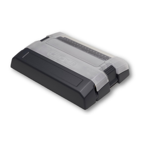
CZone DDS Guide

DDS
User & Installation Manual
V1.0

EN / CZone® DDS User & Installation Manual
2
Copyright
This document is copyright 2022 under the Creative Commons agreement. Rights are granted to research and
reproduce elements of this document for non-commercial purposes on the condition that BEP Marine is credited as the
source. Electronic re-distribution of the document in any format is restricted, to maintain quality and version control.
Important
BEP Marine strives to ensure all information is correct at the time of printing. However, the company reserves the right
to change without notice any features and specifications of either its products or associated documentation.
Translations: In the event that there is a difference between a translation of this manual and the English version, the
English version should be considered the official version.
It is the owner’s sole responsibility to install and operate the device in a manner that will not cause accidents, personal
injury, or property damage.
Use of This Manual
Copyright © 2018 BEP Marine LTD. All rights reserved.Reproduction, transfer, distribution, or storage of part or all the
contents in this document in any form without the prior written permission of BEP Marine is prohibited.This manual
serves as a guideline for the safe and effective operation, maintenance, and possible correction of minor malfunctions
of the CZone DDS.

3
EN / CZone® DDS User & Installation Manual
TABLE OF CONTENTS
1GENERAL INFORMATION 5
Use Of This Manual 5
Guarantee Specifications 5
Quality 5
Validity Of This Manual 5
Liability 5
Changes To The CZone DDS 5
2SAFETY AND INSTALLATION PRECAUTIONS 6
Warnings And Symbols 6
Use For Intended Purpose 6
Organizational Measures 6
Maintenance And Repair 6
General Safety and Installation Precautions 6
Identification Labels 7
3OVERVIEW 7
Description 7
Features 7
DDS Overview 8
LED Indicator 9
Fuse Details 10
Channel Bypass 11
System Example 12
4INSTALLATION 13
Things You Need 13
Environment 13
Mounting Guidelines 14
Planning 15
Connections 16
Initial Power Up 18
Circuit Labeling 18
Setting DIP Switch 19
5FIELD REPLACEMENT PROCEDURE 19
6BILGE PUMP MONITORING 20
7ORDERING INFORMATION 21
Parts And Accessories 21
Connector Kit 21

EN / CZone® DDS User & Installation Manual
4
8SPECIFICATIONS 22
Technical Specifications 22
NMEA 2000 PGN’s 22
Dimensions 23
9COMPLIANCE 24
TABLE OF FIGURES
Figure 1. Product Overview......................................................................................................................8
Figure 2. LED Indicator ............................................................................................................................9
Figure 3. Fuse Details ............................................................................................................................10
Figure 4. Circuit Bypass.........................................................................................................................11
Figure 5. System Example .....................................................................................................................12
Figure 6. Deutsch HDT-48-00 Crimp Tool .............................................................................................13
Figure 7. Mounting .................................................................................................................................14
Figure 8. Connections ............................................................................................................................16
Figure 9. Positive Terminal ....................................................................................................................17
Figure 10. CZone DDS Labeling............................................................................................................18
Figure 11. Bilge Pump Monitoring..........................................................................................................20
Figure 12. CZone DDS Dimensions.......................................................................................................23

5
EN / CZone® DDS User & Installation Manual
1 GENERAL INFORMATION
USE OF THIS MANUAL
Copyright © 2022 BEP Marine. All rights reserved.Reproduction, transfer, distribution, or storage of part or all the
contents in this document in any form without the prior written permission of BEP Marine is prohibited.This manual
serves as a guideline for the safe and effective operation, maintenance, and possible correction of minor malfunctions
of the CZone DDS, referred to as DDS in this manual.
This manual is valid for the following models:
Description
Part number
Czone DDS Interface Only
80-911-0260-01
It is obligatory that every person who works on or with the DDS is completely familiar with the contents of this manual,
and that he/she carefully follows the instructions contained herein.
Installation of, and work on the DDS, may only be carried out by qualified, authorized, and trained personnel, consistent
with the locally applicable standards and taking into consideration the safety guidelines and measures (chapter 2 of this
manual). Please keep this manual in a secure place!
GUARANTEE SPECIFICATIONS
BEP Marine guarantees that this unit has been built according to the legally applicable standards and specifications.
Should work take place which is not in accordance with the guidelines, instructions and specifications contained in this
Installation manual, then damage may occur and/or the unit may not fulfil its specifications. All these matters may mean
that the guarantee becomes invalid.
QUALITY
During their production and prior to their delivery, all our units are extensively tested and inspected. The standard
guarantee period is two years.
VALIDITY OF THIS MANUAL
All the specifications, provisions and instructions contained in this manual apply solely to standard versions of the DDS,
delivered by BEP Marine.
LIABILITY
BEP can accept no liability for:
•Consequential damage due to use of the DDS. Possible errors in the manuals and the results thereof.
CHANGES TO THE CZONE DDS
Changes to the DDS may be carried out only after obtaining the written permission of BEP.
EN / CZone® DDS User & Installation Manual
6
2 SAFETY AND INSTALLATION PRECAUTIONS
WARNINGS AND SYMBOLS
Safety instructions and warnings are marked in this manual by the following pictograms:
CAUTION
Special data, restrictions, and rules with regard to preventing damage.
WARNING
A WARNING refers to possible injury to the user or significant material damage to the DDS if the user
does not (carefully) follow the procedures.
NOTE
A procedure, circumstance, etc., which deserves extra attention.
USE FOR INTENDED PURPOSE
1. The DDS is constructed as per the applicable safety-technical guidelines.
2. Use the DDS only:
•In technically correct conditions
•In a closed space, protected against rain, moisture, dust, and condensation
•Observing the instructions in the installation manual
3. Use of the DDS other than mentioned in point 2 is not considered to be consistent with the intended purpose.
BEP Marine is not liable for any damage resulting from the above.
ORGANIZATIONAL MEASURES
The user must always:
•Have access to the user's manual and be familiar with the contents of this manual
MAINTENANCE AND REPAIR
•Switch off supply to the system
•Be sure that third parties cannot reverse the measures taken
•If maintenance and repairs are required, only use original spare parts
GENERAL SAFETY AND INSTALLATION PRECAUTIONS
•Connection and protection must be done in accordance with local standards
•Do not work on the DDS or system if it is still connected to a power source. Only allow changes in your
electrical system tobe carried out by qualified electricians
•Check the wiring at least once a year. Defects such as loose connections, burned cables, etc. must be
corrected immediately

7
EN / CZone® DDS User & Installation Manual
IDENTIFICATION LABELS
Important information for service or maintenance can be found on the identification labels.
3 OVERVIEW
DESCRIPTION
The DDS module uses a combination of MOSFET switching technology and relay output channels to achieve a desirably
small footprint. The CZone DDS has advanced bilge pump functionality on all relay output channels, allowing bilge pump
control and external (automatic) voltage detection from a single wire.
FEATURES
•12 or 24V system voltage (60A max)
•NMEA2000 interface
•12 Relay channels
•5 MOSFET channels with Over-Current Protection
•3 Analog Inputs (Voltage or Resistance)
•5 Positive/Negative Digital Outputs and Inputs
•5 Positive Digital Outputs and Inputs
•Advanced bilge pump functionality on all relay output channels
•Automotive mini fuses (ATM fuses)
•12 True bypass fuse position for relays
•Compliance – Ignition Protected, CE, RCM, FCC, UK-CA
CAUTION – Never remove the
identification labels, this will void
the warranty.
Serial Number. Label located on
top of the DDS unit.
Part Number. Label located on the
front of the DDS unit.

EN / CZone® DDS User & Installation Manual
8
DDS OVERVIEW
Component
1
LED Indicator
2
Circuit Fuses
3
Main Positive Supply Terminal (M8 Stud)
4
Connector A - AT06-12SA
5
Connector B - AT06-12SB
6
Connector C - AT06-12SC
7
Connector D - AT06-12SD
8
NMEA2000 Micro C Connector
9
Fuse Removal Tool
10
Fuse Panel Cover
Figure 1. Product Overview
2
3
4
10
5
6
7
8
1
9

9
EN / CZone® DDS User & Installation Manual
LED INDICATOR
1. LED Indicator
Colour
Description
Off
No Power
Solid Green
Normal / OK
Solid Red
Low Voltage
1 Red Flash
Module Not Configured
2 Red Flash
Configuration Conflict
3 Red Flash
DIP Switch Conflict
5 Red Flash
No Modules Detected
7 Red Flash
Over Current / Fuse Blown on Any Configured Output Channel
9 Red Flash
Missing Commander on Any Configured Output Channel
Figure 2. LED Indicator
1

EN / CZone® DDS User & Installation Manual
10
FUSE DETAILS
Fuses are not included with the DDS Module. The DDS module supports EATON Bussmann ATM or Littelfuse®MINI®
blade fuses.
NOTE – Care must be taken with 24V systems, 20A and 10A channels are limited to 5A each.
Fuse Function
12V Max Channel
Rating
24V Max Channel
Rating
1
20A Relay Output 1
20A
5A
2
20A Relay Output 2
20A
5A
3
10A Relay Output 1
10A
5A
4
10A Relay Output 2
10A
5A
5
10A Relay Output 3
10A
5A
6
10A Relay Output 4
10A
5A
7
5A Relay Output 1
5A
5A
8
5A Relay Output 2
5A
5A
9
5A Relay Output 3
5A
5A
10
5A Relay Output 4
5A
5A
11
2A Relay Output 1
2A
2A
12
2A Relay Output 2
2A
2A
13
5A 2x MOSFET Output
10A
10A
14
2A 3X MOSFET Output and Power Output
10A
10A
Figure 3. Fuse Details

11
EN / CZone® DDS User & Installation Manual
CHANNEL BYPASS
The DDS relay output channels can be bypassed manually by changing the position of the fuse. If a channel is
bypassed, the load will be powered directly via the fuse. The fuses need to be in the normal position for the output to
be controlled via CZone.
Position
Function
1
Normal Operation
2
Bypass Operation
Figure 4. Circuit Bypass
2
1

EN / CZone® DDS User & Installation Manual
12
SYSTEM EXAMPLE
HOUSE BATT
12V
TM
CZONE TOUCH 5
NMEA 2000 NETWORK
CZONE KEYPAD
COCKPIT LIGHT
SWITCH TO NEG
SALOON LIGHT
SWITCH TO NEG
CABIN
LIGHTS MOSFET
SALOON
LIGHTS MOSFET
0-5V FRESHWATER
TANK SENDER
10-180? FUEL
TANK SENDER
CABIN
LIGHTS MOSFET
COCKPIT
LIGHT MOSFET CABIN LIGHT
SWITCH TO NEG
CABIN LIGHT
SWITCH TO NEG
SWITCH INDICATORS
CONNECTOR A
RELAY CHANNEL OUTPUTS
CONNECTOR B
MOSFET CHANNEL OUTPUTS, SIGNAL INPUTS
CONNECTOR C & D
SWITCH INPUTS, DIGITAL OUTPUTS
BAIT TANK
PUMP RELAY
24HR BILGE PUMP
FLOAT SWITCH
NAVIGATION
LIGHTS RELAY
ENGINE ROOM
LIGHTS RELAY
GALLEY
LIGHT RELAY
ELECTRONICS
RELAY
BILGE
PUMP RELAY
SALTWATER
PUMP RELAY
FRESHWATER
PUMP RELAY
Figure 5. System Example

13
EN / CZone® DDS User & Installation Manual
4 INSTALLATION
THINGS YOU NEED
•CZone DDS Interface
•CZone DDS Connector Kit (80-911-0261-00)
•4 x 10G (5mm) panhead self-tapping screws or bolts for mounting DDS to surface (not supplied)
•HDT-48-00 Deutsch crimp tool for crimping 0.5mm-4mm (20-12AWG) wire
•NMEA2000 drop cable and T-connector
•Screwdriver and drill bits
•Electrical Tools
•Silicone grease (lubricating connector seals)
Figure 6. Deutsch HDT-48-00 Crimp Tool
ENVIRONMENT
Obey the following stipulations during installation:
•Ensure the DDS is located in an easily accessible location for quick access to module.
•Ensure mounting location is well ventilated and free from moisture. For small enclosures, fan forced ventilation
should be considered.
•Ensure LED indicator is easily visible for troubleshooting.
•Ensure circuit labels are fitted and all channels labelled correctly.
•The DDS must be mounted at least 50mm away from high current carrying conductors such as anchor winches,
bow thruster cables, speakers, transformers, and other high inductive loads.
•Ensure the bulkhead that the unit will be attached to is sufficiently strong to take the weight of the unit and
attached cables.
•Ensure there is at least 10mm clearance around the sides and top of the DDS.
•All connectors must be installed to achieve IP65 rating with unused channels blocked with blocking pins
(Amphenol Part # 114017).

EN / CZone® DDS User & Installation Manual
14
MOUNTING GUIDELINES
Do Not:
•Mount any part where it can be used as a hand hold.
•Mount any part where it might be submerged or exposed to moisture.
•Mount in a way so that moisture or condensation water can follow the cables into the device.
Do:
•Consider the overall width and height requirements.
•Leave sufficient clearance to connect all relevant cables.
•Check that it is possible to route cables to the intended mounting location.
1. Place the DDS on a solid flat surface. Mark the lower screw locations.
2. Remove the DDS and partially install lower screws using 10G (5mm) self-tapping screws or bolts.
3. Slot the DDS on to the bottom screws and install upper retaining screws.
4. Torque down each mounting screw, 6Nm (53.1in/lbs.) max.
5. Ensure enough space is left below the DDS to easily install cable connectors and access for maintenance.
NOTE – If mounting vertically is required, the main positive stud of the DDS must remain orientated downwards
with connections made to the right-hand side of the module.
Figure 7. Mounting

15
EN / CZone® DDS User & Installation Manual
PLANNING
Make a list of all inputs and outputs to be wired to the DDS and take note of the output channel ratings and input channel
functions as shown in the tables below. Assign each input and output to a channel on the DDS, ensuring loads are wired
to the appropriate channel rating and function.
•Relay Output – Relay switched output channels, suitable for general loads, take note of current rating for
each channel on 12V and 24V systems.
•MOSFET Output – MOSFET driven outputs can be set to ON/OFF or Pulse Width Modulation (PWM) mode
to dim lights during configuration. Inrush current will need to be kept below 130% of maximum channel
current.
•Signal Input – 0-30V or 0-1000ohm, e.g. 0-5V Sender, 10-180ohm Sender, 240-33ohm Sender.
•Switch Input – Switch Inputs, take note of channel POS or NEG support.
•Digital Output –
oUp to 150mA output driving unsuppressed inductive loads. E.g., relay coil.
oUp to 250mA output driving non-inductive loads such as indicators, control circuits etc. (Relay coils up
to 250mA require the addition of a freewheeling diode)
•System Ground – Required to be grounded to vessel/vehicle common ground.
•Power Output – 24 hour fused output for positive input channels.
•Ground – Common ground for switch to NEG references or status LED grounds.
Connector A (Grey)
PIN # Function
A1,
A12
20A Relay Output 1 (Both pins required to be
paralleled for loads over 10A)
A2,
A11
20A Relay Output 2 (Both pins required to be
paralleled for loads over 10A)
A3 10A Relay Output 1
A4
10A Relay Output 2
A5
10A Relay Output 3
A6
10A Relay Output 4
A7
5A Relay Output 1
A8 5A Relay Output 2
A9
5A Relay Output 3
A10
5A Relay Output 4
Connector B (Black)
PIN #
Function
B1 2A Relay Output 1
B2
2A Relay Output 2
B3
Signal Input 1
B4
Signal Input 2
B5
Signal Input 3
B6 System Ground
B7
System Ground
B8
5A MOSFET Output 2
B9
5A MOSFET Output 1
B10
2A MOSFET Output 3
B11 2A MOSFET Output 2
B12
2A MOSFET Output 1
Connector C (Green)
PIN #
Function
C1 Switch Input 1 (POS/NEG)
C2
Switch Input 2 (POS/NEG)
C3
Switch Input 3 (POS/NEG)
C4
Switch Input 4 (POS/NEG)
C5
Switch Input 5 (POS/NEG)
C6 Power Output
C7
Ground
C8
Digital Output 5 (POS/NEG)
C9
Digital Output 4 (POS/NEG)
C10
Digital Output 3 (POS/NEG)
C11 Digital Output 2 (POS/NEG)
C12
Digital Output 1 (POS/NEG)
Connector D (Brown)
PIN #
Function
D1
Switch Input 6 (POS)
D2 Switch Input 7 (POS)
D3
Switch Input 8 (POS)
D4
Switch Input 9 (POS)
D5
Switch Input 10 (POS)
D6
Power Output
D7 Ground
D8
Digital Output 10 (POS)
D9
Digital Output 9 (POS)
D10
Digital Output 8 (POS)
D11
Digital Output 7 (POS)
D12 Digital Output 6 (POS)

EN / CZone® DDS User & Installation Manual
16
CONNECTIONS
1. Connector A consists of 10x positive relay outputs. Carefully check each required load against the table
above taking into consideration the relay channel ratings.
1. Referring to the load list, strip and crimp the output channel cables with the appropriate Amphenol contact
and crimp tool.
2. Insert the contacts into the AT06-12SA plug following the plugs position numbers and secure using the
locking wedge.
3. Any unused pins in the connector should be plugged with sealing plugs to maintain the IP65 rating.
(Amphenol Part # A114017).
4. Before inserting the connector it’s highly recommended to apply a small amount of silicone grease along
the sealing surfaces/gasket. This will make assembly/disassembly easier.
5. Insert the connector into the DDS until it clicks into place.
6. Secure and neaten up the cables against the bulkhead to reduce the strain on the connectors.
NOTE – For 20A relay channels 1 and 2, if the connected load exceeds 10A both pins of the channel must
be connected in parallel to the load. Both legs of the channel require external 10A fuses fitted before they
parallel together. Both channel output pins will be live with output turned on, if only one pin is required, a sealing
plug (Amphenol Part # A114017) should be inserted into unused pin.
2. Connector B consists of 2x positive relay outputs, 5x MOSFET outputs, 3x analog inputs and the system
ground inputs. Carefully check each required load/input against the table above taking into consideration
channel function and limitations.
1. Referring to the load and analog input list, strip and crimp the cables with the appropriate Amphenol contact
and crimp tool.
2. Insert the contacts into the AT06-12SB plug following the plugs position numbers and secure using the
locking wedge.
3. Any unused pins in the connector should be plugged with sealing plugs to maintain the IP65 rating.
(Amphenol Part # A114017).
4. Before inserting the connector it’s highly recommended to apply a small amount of silicone grease along
the sealing surfaces/gasket. This will make assembly/disassembly easier.
5. Insert the connector into the DDS until it clicks into place.
6. Secure and neaten up the cables against the bulkhead to reduce the strain on the connectors.
NOTE – System Ground inputs on Connector B MUST be connected to vessel/vehicle common ground.
Figure 8. Connections
1
2
3
4
5

17
EN / CZone® DDS User & Installation Manual
3. Connector C consists of 5x Pos/Neg switch inputs and 5x Pos/Neg 250mA digital outputs. Carefully check
the channel limitations in the table above.
1. Referring to the switch input and digital output list, strip and crimp the cables with the appropriate Amphenol
contact and crimp tool.
2. Insert the contacts into the AT06-12SC plug following the plugs position numbers and secure using the
locking wedge.
3. Any unused pins in the connector should be plugged with sealing plugs to maintain the IP65 rating.
(Amphenol Part # A114017).
4. Before inserting the connector it’s highly recommended to apply a small amount of silicone grease along
the sealing surfaces/gasket. This will make assembly/disassembly easier.
5. Insert the connector into the DDS until it clicks into place.
6. Secure and neaten up the cables against the bulkhead to reduce the strain on the connectors.
4. Connector D consists of 5x switch inputs (positive only) and 5x 250mA digital outputs (positive only).
Carefully check the channel limitations in the table above.
7. Referring to the digital input and digital output list, strip and crimp the cables with the appropriate Amphenol
contact and crimp tool.
8. Insert the contacts into the AT06-12SD plug following the plugs position numbers and secure using the
locking wedge.
9. Any unused pins in the connector should be plugged with sealing plugs to maintain the IP65 rating.
(Amphenol Part # A114017).
10. Before inserting the connector it’s highly recommended to apply a small amount of silicone grease along
the sealing surfaces/gasket. This will make assembly/disassembly easier.
11. Insert the connector into the DDS until it clicks into place.
12. Secure and neaten up the cables against the bulkhead to reduce the strain on the connectors.
NOTE – Connector D digital inputs are ‘Switch to POS’ only and digital outputs are 250mA POS output only.
5. Connect NMEA2000 network
1. Connect a NMEA2000 drop cable from the DDS to the vessel/vehicle NMEA2000 backbone.
2. Ensure the NMEA2000 network is properly terminated and connected to a 12V power source (Do not
power up network yet).
6. Connect DC Positive
1. Connect an appropriately sized and fused cable from the battery
positive terminal to the DDS’s M8 positive stud.
2. The positive cable must be of sufficient size to carry the
maximum current of all loads connected to the DDS and have a
fuse/circuit breaker rated to protect the cable, volt drop should
be kept to a minimum.
3. Maximum recommended cable size is 50mm² (1/0 AWG).
Cables larger than 50mm² (1/0 AWG) should be connected to a
joiner stud first with a link to the DDS.
4. Ensure the M8 nut is torqued to 3.9Nm (34.5in/lbs.).
6
Figure 9. Positive Terminal

EN / CZone® DDS User & Installation Manual
18
INITIAL POWER UP
1. Check all plugs are securely seated and power connections are tight.
2. Turn the switch/circuit breaker on supplying the DDS’s main positive stud.
3. Power up the NMEA2000 network.
4. Connect to NMEA2000 network via CAN-USB interface and open CZone Configuration Tool.
5. Set DIP Switch for new module. Instructions for setting the DIP switch in the CZone Configuration Tool is
available in Section 4.8.
6. With the CZone Configuration Tool, check the software version of all modules on the network, including the
DDS, and update if necessary.
7. Write configuration file to the DDS and the rest of the CZone modules on the system (Refer to the CZone
Configuration Tool Instructions for details on how to configure the system).
8. Test all inputs and outputs for configured functionality.
CIRCUIT LABELING
Label the Circuits
•Using a fine tip marker pen, label each output corresponding to the configured load.
•Correct labelling of the loads will make fault finding of the vessel/vehicle system easier.
Figure 10. CZone DDS Labeling

19
EN / CZone® DDS User & Installation Manual
SETTING DIP SWITCH
As there are no physical DIP switches on the DDS, the unit will come with a factory default DIP switch setting of
11111111. If there is more than one DDS or a conflicting DIP switch on the network, the installer can explicitly set the
DIP switch of a detected DDS form the Configuration Tool.
1. When adding the DDS module to a configuration, select the DIP switch setting, either from the dropdown or
‘Edit Dipswitch Graphically’ tab.
2. Select the DDS unit you are targeting from the list. The serial number can be found on the label on top of the
DDS module.
3. Click ‘OK’ on both windows to add new module to configuration.
5 Field Replacement Procedure
Field replacement of a DDS is possible unless there is more than one DDS in a system or there is an absence of another
CZone device. The DDS replacement will require a copy of the vessel’s/vehicle’s configuration, a laptop with the CZone
Configuration Tool, and a USB-CAN adaptor to write the config to the new module.
Field replacement of a DDS is possible under the following circumstances:
•There is only one DDS module in the vessel’s/vehicle’s CZone configuration.
•There is another CZone device present on the network.
If the above circumstances are true, replacement is possible with the following steps:
1. Turn off the breaker supplying the faulty DDS’s main power stud and switch off the power supplying the CZone
NMEA2000 network, disconnect the faulty DDS module’s connections.
2. Remove the faulty module and replace with a new one. Connect each of the connectors, the NMEA2000 drop
cable, and main positive stud.
3. Re-power the NMEA2000 network and the DDS’s main supply.
4. Wait for the new module to claim the config that is present on the network (indicated by flashing LEDs).
5. If the configured DDS DIP switch is different to that of the new DDS, the new DDS will automatically change its
DIP switch to the configured value.
1
2
3

EN / CZone® DDS User & Installation Manual
20
6 Bilge Pump Monitoring
The CZone DDS has advanced bilge pump functionality on all relay output channels. This allows pump control and
external (automatic) voltage detection from a single wire. CZone status indicators will illuminate if an external voltage is
detected from automatic float switches or CZone can trigger system alarms to notify owners of automatic bilge pump
operation, and optionally use this run signal to turn on other circuits, like additional pumps. You can track total run time
of pumps and display the information on CZone Display Interfaces. Delays can be configured to the ‘External Systems
On Alarm’ to stop nuisance alarm tripping from a float switch.
BILGE PUMP
FLOAT SWITCH
12V BATTERY
BILGE PUMP AUTOMATIC 24HR SUPPLY
BILGE PUMP NEGATIVE
CZONE MANUAL OVERRIDE / RUN INDICATION
Figure 11. Bilge Pump Monitoring
This manual suits for next models
1
Table of contents
Other CZone Recording Equipment manuals

CZone
CZone Network Bridge Interface Installation guide

CZone
CZone Motor Output Interface Guide

CZone
CZone 80-911-0005-00 Guide

CZone
CZone Display Interface Installation guide

CZone
CZone COI Operating manual

CZone
CZone Meter Interface Installation guide

CZone
CZone Control 1 Operating manual

CZone
CZone Signal Interface Guide

CZone
CZone 80-911-0009-00 Guide

CZone
CZone Switch Control Interface Installation guide