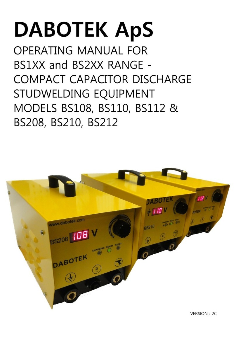
dabotek BS310 User manual

M A N U A L B S 3 1 0
D A B O T E K
D A B O T E K T r a d i n g A p S
B i r k e d a m 1 0 C
D K - 6 0 0 0 K o l d i n g ;
T E L + 4 5 5 5 0 5 6 6 6
F A X + 4 5 5 5 0 4 9 5

Inhalt
Operating manual for welding unit
Type: BS304 / BD306 / BS308 / BS310
BSS
BS3xx
Page 2
22.01.99
Table of contents
Copyright 4..........................................................................
General 5............................................................................
Who should read these instructions? 5................................................
What is included in these instructions? 5..............................................
What is not included in these instructions? 5...........................................
Further information 5...............................................................
Customer Service 5..................................................................
Safety 6.............................................................................
Precautions for using the stud welding equipment
and its components 6................................................................
Description 7........................................................................
Welding method 7..................................................................
Intended purpose 8..................................................................
General 8............................................................................
Field of application of the welding equipment 8........................................
Standard stud dimensions 8..........................................................
The control panel 9..................................................................
Clear text display 9.................................................................
MODE key 9.......................................................................
ENTER key 9......................................................................
RIGHT ARROW key 9...............................................................
LEFT ARROW key 9................................................................
UP ARROW -- DOWN ARROW key 9..................................................
The connection panel 10..............................................................
The back panel 11.....................................................................
Mains connection 11.................................................................
Symbols in the display 12.............................................................
The main menu items 12.............................................................
Notes for the operator 12.............................................................
Fault signals 12.....................................................................
Operating modes 13...................................................................
Quick menu 13.....................................................................
Main menu 14......................................................................
Installation 15........................................................................
Setting up the stud welding equipment 15..............................................
Unpacking 15......................................................................
Setting up 15.......................................................................

Inhalt
Operating manual for welding unit
Type: BS304 / BS306 / BS308 / BS310
BSS
BS3xx
Page 3
22.01.99
Connection 15........................................................................
Connecting the power cable to the welding equipment 15................................
Connecting to the mains supply 16....................................................
Connecting the welding head 16......................................................
Connecting the ground cables 16.....................................................
Startup 17............................................................................
Maintenance and service 18...........................................................
Replacing the Filter 18...............................................................
Troubleshooting 19...................................................................
Replacing the fuse 19...............................................................
Transport 20..........................................................................
Transport damages 20...............................................................
Spare parts 21........................................................................
BS304 Welding equipment 22..........................................................
BS306 Welding equipment 23..........................................................
BS308 Welding equipment 24..........................................................
BS310 Welding equipment 25..........................................................
Appendix 26..........................................................................
EC Conformity Declaration 26.........................................................
EMC Conformity Certificate 26........................................................

DABOTEK Trading ApS
Birkedam 10 C
DK-6000 Kolding
Phone: +45 7930 7500
FAX : +45 7930 7505
The copyright in these Operating Instruction remains with DABOTEK Trading ApS.
The specification and illustrations of these Operating Instructions shall not be reproduced or circulated
nor shall they be used by unauthorized persons or parties or communicated to others for purposes of com-
petition.
DABOTEK Trading ApS reserve the right to make any technical modifications, without prior
notice, from the statements and specifications in these Operating Instructions if and when such modifi-
cations become necessary in order to improve our product.
These Operating Instructions were written and edited very carefully. Should you find errors or mistakes,
though, we will appreciate if you let us know.

General
Who should read these instructions?
These instructions are meant for
- the operators of the stud welding equipment
- the ultimate customer.s personnel operating and connecting the equipment
- the field engineer of DABOTEK Trading ApS.
What is included in these instructions?
In these instructions you find information on
- Operation
- Maintenance and service
- Transport, installation and connection
- Technical specifications
- Spare parts
What is not included in these instructions?
Repair documentation is not included in these instructions.
Further information
Additional technical information beyond these instructions, if needed, is available from our agents or
immediately from headquarters.
These instructions convey important information prerequisite for safe working with the stud welding
equipment.
Operating personnel must be able to refer to these instructions if necessary.
Therefore, make sure the instructions are available to them at the appropriate time.
If you sell the equipment pass these instructions on to the new owners. Please immediately send us the
name and address of the new owners in case it becomes necessary unexpectedly to contact themabout
the safety of the equipment.
Hinweis: Study these instructions carefully before installing the equipment. In particular, pay attention
to the safety hints.
Customer Service
DABOTEK Trading ApS
Birkedam 10C.
DK-6000 Kolding
To contact our Customer Service use
Phone no. +45 7930 7500
Fax no. +45 7930 7505
You will need the .Bolzenschweißen. (stud welding) department.
Please specify the details of the fault or malfunction:
Machine or article number
Welding equipment type and serial numbers
Welding head type
Description of the faults that have occurred.
Please confirm every service request in writing.

BS3xx--engl-- 220199
Operating manual for welding unit
Type: BS304 / BD306 / BS308 / BS310
BSS
BS3xx
Page 6
22.01.99
For any welding problems, or if you are interested in sample weldings, do not hesitate to contact us.
Our welding laboratory is there ready to help you.
Safety
SThis stud welding equipment is a state--of--the--art product and operationally reliable. Hazards may,
however, be caused by unskilled personnel connecting and operating the equipment improperly or
using it in any other than the intended manner.
SEverybody concerned with connecting, operating and maintaining this equipment must have read
and understood the appropriate instructions and in particular the section on ”Safety”.
SThe equipment components may only be connected, operated and maintained by personnel familiar
with those tasks and aware of the hazards.
SAll relevant regulations and any other generally accepted rules must be complied with.
SShould you still be in doubt about some detail or other make sure to consult your superiors or the ma-
nufacturers.
SNever work or operate in any way that might adversely affect the safety of the equipment, equipment
components, or machine.
SSafety devices must never be dismounted or put out of operation. Safety devices are there to protect
from severe damage.
SEquipment components to be completed into functional machines or systems at the operator’s must
be equipped with state--of--the--art safety devices by the operator.
SFor any apparent damages and defects impairing the safety and for any unusual noise or smell, switch
off the equipment or machine and notify your superiors..
SIf recognizable faults or shortcomings occur which reduce safety, as well as unusual noises and
smells, switch the appliances or machine off and inform your supervisor
SHave the equipment and in particular connection lines with plugs checked for proper condition by
an expert; this should be done every six months or earlier.
SDo not allow the connection leads to hang over sharp edges.
SDo not lay the connection leads across traffic lanes or near heat sources.
SAll connection, operation and maintenance of the equipment components or machines must be done
in accordance with local safety and accident prevention regulations
.
Warning against unauthorized alteration or modification.
Any intended alterations and modifications must be brought to the manufacturer’s notice. For reasons
of safety, unauthorized alterations or modifications cannot be allowed. Any unauthorized alterations or
modifications cause forfeiture of warranty.
Precautions for using the stud welding equipment
and its components
Remark: All maintenance and repair work must only be carried out by trained technical personnel.
Protective arrangements must not be removed.
Make sure to switch off the equipment before replacing wear parts (electrical, pneumatic, me-
chanical).
ALWAYS pull the mains plug out of the mains socket!
MORTAL DANGER !!!
Hinweis: Wait for 10 seconds after switching off the welding equipment because the capacitor battery
is discharged.
Remark: IMPORTANT! A residual charging voltage is present !

BS3xx--engl-- 220199
Operating manual for welding unit
Type: BS304 / BS306 / BS308 / BS310
BSS
BS3xx
Page 7
22.01.99
DO NOT USE ANY liquids when cleaning the appliance! Liquids can enter the electrical sy-
stem.
Remark: Do not look into the arc while welding is in progress !
Remark: Protect your skin, eyes and clothing gainst weld splashes.
Remark: Make sure that there are no combustible objects in the vicinity of the welding area or the weld
spark area.
Remark: Protect your ears against noise!
Do not move magnetizable objects into the vicinity of the welding set.
The welding process releases electromagnetic fields and, for example, watches, magnetic cards of all
kinds can be rendered useless through this.
Persons who carry a heart pacemaker must be made aware of these electomagnetic fields.
The possibility of the heart pacemaker being affected cannot be excluded.
Do not touch or put a hand into moving or live parts.
Description
Welding method
The welding method is capacitor discharge wel-
ding with tip ignition. No shielding gas is used, not
even for the welding of aluminium.
SThe welding stud is accelerated by the welding head to move at a speed of 0.5--1m/sec in the direction
of the base material. At the same time, the capacitor battery is switched on.
SThe ignition tip touches the base material and discharge current begins to flow. The ignition tip is hea-
ted up by high discharge current and evaporates all of a sudden.
SThe arc is ignited. It burns for some 1 or 2 milliseconds and melts on the base material.
SThe welding stud dips into the weld pool.
SHeat absorption by the base material causes the weld pool to solidify.
SThe welding process is finished, leaving the stud firmly attached to the base material.
accelerating
igniting melting solidfying finished
Welding process approx. 3--4 ms
Time t [ms]
Time t [ms]01234
Speed
Welding current [I]
Arc voltage [V]

Intended purpose
The BS304/306/308/310 line of stud welding equipment is intended to weld studs under DIN32501 or
special-purpose welding elements,manufactured DABOTEK, onto appropriatematerials.
Welding method: Capacitor discharge welding with tip ignition.
You can attach DABOTEK handguns, semi-automatic or automatic welding heads to the wel-
ding equipment. Anything going beyond that is considered outside the intended (contractual) use. The
manufacturer cannot be held responsible for any damages resulting from such use. The operator bears
the risk.
The term .intended use. includes compliance with the Operating Instructions and the specifiedmainte-
nance conditions.
The welding equipment is intended primarily for use in industrial areas.
In other areas, we cannot always warrant electromagnetic compatibility.
General
The BS304/306/308/310 types of stud welding equipment belong to the same equipment family and are
distinguished only by the amount of energy each of them uses for welding.
- All types in this line are equipped with processor control.
- Capacitor charging voltage can be entered directly in volts or indirectly by entering the stud diameter.
When entering the stud diameter, the appliance sets itself automatically to anempirical value. Correc-
tions are possible.
- Different operating states are displayed by symbols in the display.
Field of application of the welding equipment
All DABOTEK welding heads can be attached.
Ever since 01.01.96, all welding heads come equipped with a 12-pole equipment plug.
If you want to connect older welding heads you need to change the equipment plug or use a suitable
adapter. Such adapters are available from our delivery programme.
Standard stud dimensions
The standard studs according to DIN 32501 listed in the following table can be welded using the BS
... line of equipment. For our complete stud program, please refer to our stud catalogue.
Equipment
type
Stud Ø Material
BS 304 1-4 St. 37-3 1.4303 AlMg3 CuZn37
BS 306 2.5-6 St. 37-3 1.4303 AlMg3 CuZn37
BS 308 3-6 AlMg3 CuZn37
3-8 St. 37-3 1.4303
BS 310 3-6 AlMg3 CuZn37
3-8 St. 37-3 1.4303
10 St. 37-3 1.4303
Hinweis: The values shown in the above table are approximate. Weldability will vary with the welding
head, the material, and the surface condition of the workpiece. Specific cases may deviate
from the values listed above. Most materials feature a strong decline of weldability for stud
diameters of 6 mm and more. Make sure to trail-weld before you start production welding!

BS3xx--engl-- 220199
Operating manual for welding unit
Type: BS304 / BS306 / BS308 / BS310
BSS
BS3xx
Page 9
22.01.99
The control panel
100 V
OBO Bettermann
MODE
ENTER
BS 308
Text display
Cursor
Clear text display
The clear text display shows in normal operation the
charging voltage of the capacitors in volts, or spe-
cial operating conditions.
An explanation of the symbols for the operating
conditions is given on page 12.
MODE key
With the ”MODE” key you can select various condi-
tions(MENU POINTS).
ENTER key
With the ”ENTER” key you confirm the parameter
values set at the appliance and return to the main
menu (basic position).
RIGHT ARROW key
With the ”RIGHT ARROW” key you change in the
main menu to the menu options or move the CUR-
SOR in the clear text display to the right.
LEFT ARROW key
With the ”LEFT ARROW” key you return to the menu
options or move the CURSOR in the clear text dis-
play to the left.
UP ARROW -- DOWN ARROW key
With the ”UP ARROW” and ”DOWN ARROW” key
you change in the menue options to the sub--menus
or increase or decrease the charging voltage of the
capacitors.
100 V
MODE
ENTER
right
left
up
down

The connection panel
12-pin socket for the control cable of the welding
gun.
As from 1.1.1996 some DABOTEK Trading ApS welding
guns and welding heads will have 12-pin appliance
plugs. Older welding guns and welding heads can
be connected by replacing the appliance plugs or
by means of an adapter.
Socket for welding cable of the welding gun (wel-
ding head).
Socket for welding cable of the grounding connec-
tions.

BS3xx--engl-- 220199
Operating manual for welding unit
Type: BS304 / BS306 / BS308 / BS310
BSS
BS3xx
Page 11
22.01.99
The back panel
Mains socket
Type plate
Vent hole
OBO Bettermann
Mains connection
Power ON/OFF switch
Fuse carrier for
fuse F1 (3.15A mT)
Cold equipment plug
Mains supply 110V--240V/
500VA

Symbols in the display
The main menu items
With this menu item you can
* switch the welding set to normal operation.
With this menu item you can
* set the charging voltage.
With this menu item you can
* set the stud diameter.
Notes for the operator
Welding capacitors are charged.
Set is not ready for welding while charging is in pro-
cess.
Welding capacitors are discharged.
Set is not ready for welding while discharging is in
process.
Turn off signal.
Fault signals
The temperature in the appliance is too high.
The appliance is during this display not operational.
Appliance faulty!
Switch appliance off immediatly and contact the af-
tersales service of DABOTEK Trading ApS.
Phone: Denmark: +45 7930 7500

BS3xx--engl-- 220199
Operating manual for welding unit
Type: BS304 / BS306 / BS308 / BS310
BSS
BS3xx
Page 13
22.01.99
Operating modes
You can operate the set in two different ways.
* Inout of the charging voltage ”QUICK MENU”
* Input of the stud diameter ”MAIN MENU”
Quick menu
If you quickly want to carrry out a charge in the capacitor voltage, proceed as follows:
Action Switch Display
Switch the welding set on.
The display shows the last se-
lected charging voltage,
e.g. 100V.
Briefly hit the ”MODE” key
(less than 2sec.)
The CURSOR starts to blink. MODE
cursor blinks
Place the CURSOR with the
“RIGHT ARROW” or “LEFT AR-
ROW” key in the appropriate
units:
“ONES”, “TENS” or “HUN-
DREDS” position.
left right hundreds tens ones
Set the new value at the prese-
lected position with the “UP
ARROW” or “DOWN ARROW”
key.
Example: change from 100V to
150V.
up
down
Have you set the value?
Now confirm with the ”ENTER”
key.
When a “BEEP” is sounded, the
welding set has accepted the
new value.
ENTER
beep
The welding capacitors are
charged or discharged to the
selected value.
or
The display shows the newly
set value.
The welding unit is now ready
for operation.

BS3xx--engl-- 220199
Operating manual for welding unit
Type: BS304 / BD306 / BS308 / BS310
BSS
BS3xx
Page 14
22.01.99
Main menu
If you want to determine the charging voltage of the capacitors by entering the stud diameter, proceed
as follows:
Action Switch Display
Switch on the appliance.
The display shows the last se-
lected value,
e.g. 100V.
Press the ”MODE” key at least
2sec.
The display shows the last dia-
meter
MODE
cursor blinks
Set the new value with the “UP
ARROW” or “DOWN ARROW”
key.
Example: change from 4mm to
8mm.
up
down
cursor blinks
Have you set the value?
Now confirm with the “ENTER”
key.
When a BEEP is sounded, the
appliance has accepted th new
value
ENTER
beep
The processor sets the correct
charging voltage for the selec-
ted diameter.
During setting, the symbols ap-
pearing in the display indicate
whether the charging voltage is
being increased or reduced.
or
When the setting has been
made, the value of the char-
ging voltage appears in the
display. The appliance is now
ready for operation.

BS3xx--engl-- 220199
Operating manual for welding unit
Type: BS304 / BS306 / BS308 / BS310
BSS
BS3xx
Page 15
22.01.99
Installation
This chapter describes how to set up the welding equipment.
Hinweis: The equipment may only be installed and connected by personnel familiar with those tasks
and made aware of the hazards involved.
Setting up the stud welding equipment
Unpacking
SFirst remove the accompanying materials and accessories from the package. Keep the transport
package in a safe place.
SAlways use this original package for transporting or shipping the equipment.
SIf you do not want to keep the packaging materials make sure they are disposed of in a non--polluting
manner.
Setting up
Choose a suitable location. Such location should meet the following requirements:
Ssufficient distance from refrigerating sets and heat sources,
Sno extreme temperature variations,
Sno direct solar radiations,
Sno excessive accmulation of dust, aggressive chemicals or vapours,
Sambient temperature between 10°and 40°C,
Srelative humidity between 20% and 80%.
Connection
Connecting the power cable to the welding equipment
Remark: Make sure the equipment is turned off.
SAt the back panel of the equipment, insert the cold
equipment plug into the cold equipment socket.
Make sure the mains voltage is correct: 110V--240V.
SUse the retaining clip to secure the cold equipment plug.
Power off
Cold equipment plug
Retaining clip

BS3xx--engl-- 220199
Operating manual for welding unit
Type: BS304 / BD306 / BS308 / BS310
BSS
BS3xx
Page 16
22.01.99
Connecting to the mains supply
Make sure the supply voltage is correct: 110V--240V
50--100Hz. The equipment automatically adjusts to
your voltage setting. Insert the plug into the mains
socket.
Connecting the welding head
Insert the 12--pole plug into the equipment socket.
There can be no mistake about the plug contacts
because the plug is protected against twisting. To
secure the plug--and--socket connection turn the
plug bushing clockwise until it stops.
Insert the welding cable plug of the gun into the wel-
ding socket.
To secure the plug--and--socket connection firmly
turn the plug clockwise until it stops.
Remark: Loose welding current connection will scorch the plug- and- socket connection. If this hap-
pens constant welding results are no longer ensured!
Connecting the ground cables
Insert the plugs of the ground cables into the
ground sockets.
To secure the plug--and--socket connection firmly
turn clockwise until it stops.
Connect the ground terminals or ground jacks to the
workpiece.
Make sure that the welding cables are laid out long.
Mains plug
Mains socket
12--pole plug
Equipment socket
Welding receptacle
Welding plug
Ground socket
Ground jack
Ground plug

BS3xx--engl-- 220199
Operating manual for welding unit
Type: BS304 / BS306 / BS308 / BS310
BSS
BS3xx
Page 17
22.01.99
Startup
SHas the set been correctly connected?
SHas the welding gun been correctly connected?
SHave the ground cabels been correctly connected?
Procedure Function element Display
Schwitch on the welding set.
The Capacitors are automatically charged to the
last selected voltage value. During th process
the charging symbol appears in the display. Af-
ter the charging the display shows the voltage,
e.g. 100V.
Now select your required parameters.
a.Entering the charging voltage
see “Quick menu”.
b.Entering the stud diameter
see “Main menu”.
MODE
MODE
2sec.
cursor blinks
To start welding, place the welding gun verti-
cally on the workpiece. Firmly push the welding
gun down. The three support feet or the support
tube must lean fully on the workpiece. Trigger
the welding gun steadily and without shaking.
The equipment starts welding. Welding can only
be started when the contact symbol appears in
the display.
or
Check your welding for strength.
If the strength is inadequate verify the equip-
ment settings and make sure that the base ma-
terial and the welding stud are suitable for wel-
ding.
Refer to the appropriate operating manual for
information on how to set and handle the wel-
ding gun (welding head).

BS3xx--engl-- 220199
Operating manual for welding unit
Type: BS304 / BD306 / BS308 / BS310
BSS
BS3xx
Page 18
22.01.99
Maintenance and service
Before any maintenance work on the equipment, make sure to switch off and disconnect the
mains plug from the socket.
Mains plug
Mains socket
Power off
Remark: To clean the equipment do not use any liquids.
Liquids might penetrate into the equipment.
DANGER OF LIFE!
Replacing the Filter
Check the dust filter at regular intervals. Replace
the dust filter when it is heavily contaminated. A
heavily contaminated dust filter will affect the venti-
lation of the equipment. The filter is accessible from
the bottom of the equipment.
Fabric insert
Filter mat
Filter cap

BS3xx--engl-- 220199
Operating manual for welding unit
Type: BS304 / BS306 / BS308 / BS310
BSS
BS3xx
Page 19
22.01.99
Troubleshooting
Stud welding set Possible faults Remedy
No display
No mains connection. Check mains connection.
Mains switch set to off Set mains switch on the back
of the welding set to on.
Fuse blow. Check mains fuse on the back
o
f
t
h
e
s
e
t
o
f
t
h
ese
t
.
Disconnect the set from the
m
a
i
n
s
D
i
s
m
o
u
n
t
f
u
s
e
c
a
r
r
i
e
r
ma
i
ns.
D
i
smoun
t
f
use carr
i
er
and replace fuse.
The display shows
Equipment temperature too
high.
Keep equipment turned on and
wait a few minutes.
Filter contaminated. Replace filter mat.
Defective fan. Replace fan by service enge-
neer.
The display shows
Main thyristor (SCR) or control-
ler defective:
Turn off the set.
Wait a few seconds and turn on
again. If the malfunction per-
sists, turn off the set and call
the OBO BETTERMANN ser-
vice department or our local
agents.
If none of the actions above is successful, contact our service department.
Replacing the fuse
STurn off the equipment.
SDisconnect the mains plug from the socket.
SRelease the retaining clip and remove the
cold equipment plug from the equipment socket.
SDismount the fuse carrier and
remove the blown fuse.
SInsert a new fuse (3,15 A mT).
SReconnect the cold equipment plug to the equipment socket.
SFasten the retaining clip.
SInsert the mains plug.
STurn on the equipment.
Cold equipment plug
fuse 3,15A mT
Retaining clip

BS3xx--engl-- 220199
Operating manual for welding unit
Type: BS304 / BD306 / BS308 / BS310
BSS
BS3xx
Page 20
22.01.99
Transport
The equipment is shipped using suitable means of transportation and appropriate packaging. Take care
to keep the transport package in a safe place. Always use this original package when you need to carry
or ship the equipment. If you do not want to keep the packaging materials make sure they are disposed
of in a non--polluting manner.
Transport damages
SIf you detect any transport damage please contact our distribution or shipping departments before
returning the shipment.
SNever return equipment unsolicitedly.
SMake sure to keep the deadlines for reporting the damages; otherwise the carriers are no longer lia-
ble.
Package damaged
on transport by
Railways Carriers
Unpack the equipment in the pre-
sence of an employee of the railways.
Have the damage inspected and file
an application for appraisal with the
goods office.
Unpack the equipment in the pre-
sence of the driver.
Have the damage attested
by the driver.
Reporting deadline: 1week Reporting deadline: 4 days
Package o.k., contents damaged on transport
on transport by
Railways Carriers
Notify the competent goods
office. Have the damage inspected
and file an application for appraisal.
Notify the carriers.
Have the damage inspected and file
an application for appraisal.
Reporting deadline: 1 week Reporting deadline: 4 days
Table of contents
Other dabotek Welding System manuals