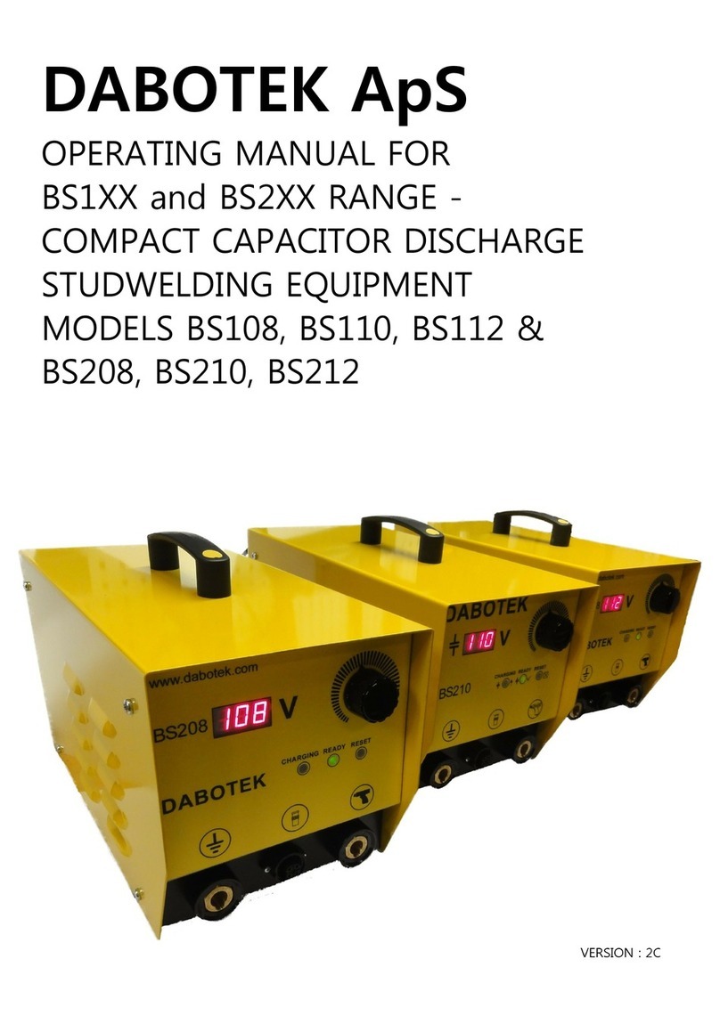
dabotek DT410 User manual

D A B O T E K
D A B O T E K T r a d i n g A p S
B i r k e d a m 1 0 C
D K - 6 0 0 0 K o l d i n g ;
T E L + 4 5 7 5 5 0 5 6 6 6
F A X + 4 5 7 5 5 0 4 7 9 5
I N S T R U K T I O N ' s M A N U A L
F O R D T 4 1 0


We will be there for you if you need us
We do not only take trouble over our customers until the date of sale but we also offer
extensive service by means of easily comprehensible operating instructions for examp-
le. We have conceived the operating instructions so that you can glance at them and
then easily work with the equipment.
In case there should be anything you do not understand or you should have difficulties
you cannot solve by means of these instructions just call us. We are always ready to
listen to your ideas, criticism and suggestions for improvement because we are there
for you.
You can get in touch with your DABOTEK -Team on
(Denmark ) +45 7930 7500
Mo-Fr 8.00-1600
Hotline (in Denmark)
In an emergency you can inform us round the clock. Then we will contact you as soon
as possible. If you call us, please give:
1. your company
2. your name
3. telephone number (where we can reach you)
4. possible cause of fault or
brief description of fault
Hotline-number: (Denmark) +45 2125 2666

Table of contents
Introductory information.....................................................4
Target group of these operating instructions.....................4
Special qualifications and regulations...............................5
Meaning of symbols..........................................................6
Field of use of the stud welding equipment ......................7
Features of the stud welding equipment...........................7
Safety information ...............................................................8
Installation and connection ..............................................12
Checking scope of delivery.............................................12
Choosing place of installation.........................................13
Transport.........................................................................13
Connection......................................................................14
Setting-up equipment and welding gun...........................15
Connecting earth cables to work piece...........................15
Setting-up welding gun...................................................15
Adjusting equipment .......................................................20
Welding...............................................................................21
Tips for stud welding.........................................................22
Studs, chucks and ceramic ferrules................................22
Adjustments....................................................................22
Avoiding magnetic blowing action...................................24
Vertical weldings.............................................................25
Checking weld joints.......................................................26
Cleaning and attendance ..................................................28
Maintenance.......................................................................29
Blowing out equipment interior .......................................29
Checking plugs and cables.............................................30
Eliminating faults...............................................................31
Technical data ....................................................................32
Guarantee...........................................................................33
Where to put the old equipment.......................................34
Certificate of EC-conformity.............................................35
Index....................................................................................36
Your equipment in overview .............................................39
After-sales service.............................................................40
Tip:
Ifyouunfoldthelast
page you will find an
overview of the
equipment.
3

Introductory information
Target group of these
operating instructions
Safety information
Before putting the equipment into operation acquaint yourself
with the contents of these operating instructions. Thus you will
achieve the best welding results and you will work safely.
These instructions are intended for operators and supervisors
of the stud welding equipment.
For the operator
Knowledgeandexperienceinthefieldofweldingarenecessary
to:
•judge the place of work
•set-up the equipment
•choose the weld stud
In addition knowledge of the handling of stud welding equip-
ment is required. This kowledge is either given by the manu-
facturer or by a trained operator.
For the operating staff
Onlypeopleover18areallowedtoweld.Knowledgeinthisline
of work is required.
For the employer
Thestaffhavetobeinstructedregularlybutatleastonceayear
according totheregulationsofthesafety-laws ofyourcountry.
Untrained or unauthorized staff are not allowed to use the stud
welding equipment.
Introductory information
4

Special qualifications and
regulations Normally there is no particular examination necessary. For the
sector of planning controls according to DIN 18 800 or Euro-
code4(afieldlaiddownbylaw)therearespecialrequirements
for the executing factory.
Examination For stud welding in the sector of planning controls there is an
examination necessary according to DIN 8563, part 10 –
securing the quality of welding works – or DIN EN ISO 14 555.
According to DIN EN ISO 14 555 – securing the quality of
welding works, stud welding of metal materials– the operating
staff have to be examined according to EN 1418 .
The welding supervision is responsible for the production and
the security of the quality.
Quality assurance In order to secure the quality DIN EN 729 – general welding
technical requirements – is applied.
Introductory information
5

Meaning of
symbols Toshape the text clearly we haveuseddifferent symbols. They
are explained as follows:
•A dot is used with enumerations.
— A dash announces works you have to carry out.
→Cross-references to other passages in the text are provi-
ded with an arrow.
The little welder has three different functions depending on
what he is holding in his hand.
The stud marks tips and hints regarding the operation.
The spanner announces tips regarding adjustments.
The warning triangle refers to important safety precautions.
Introductory information
6

Introductory information
Field of use of the
stud welding equipment
Features of the
stud welding equipment
The stud welding equipment is designed for the welding of studs
using the arc pressure welding process. The equipment only
works when a welding gun is fitted.
With the welding gun welding elements can be welded on to
suitable parent metals according to EN 13 918 – studs for arc
welding. For further use consult your country representative or
DABOTEK Denmark.
Ease of operation
The stud welding equipment is easy to operate and demands
no special exam for welders – except for the sector of planning
controls. By means of the partial mechanization of the welding
process high-quality weldings can be achieved after a short
training period.
. Safety
In order to work as safely as possible with the equipment
we have constructed it according to the regulations of the
EU and the national German regulations. Working under
increased electric danger is permitted. The equipment
meets the demands of the protection category I, I P23 and
has the “S” as well as the “CE”-sign.
Long life
The transformers, rectifiers and electronics are especially
robust and guarantee - together with the modern sheet steel
case - a long life of the equipment.
7

Safety information In this chapter you will find general advice on safety
precautions. In addition the single chapters of these ope-
ratinginstructionsrefertosafetyprecautionswhicharenot
described here.
Please observe the following pieces of advice for interest
of your own safety, your colleagues’ safety and to ensure
the safety of the equipment.
When welding with power a number of dangers can result
from undisciplined conduct. Therefore you should work
especially carefully and not under pressure. Accidents
cannot be undone.
Studweldingrequirestheusualsafetyprecautionsapplied
toarcwelding.Thesafetyprecautionsaredescribedinthe
German UVV 26.0 – welding, cutting and related
processes.
For the employer
Inform those people working with the equipment regularly
aboutthesesafety precautionsandinaccordancewiththe
legal regulations.
For the operating staff
Operators have got experience with the stud welding
equipment and are able to realize and to avert dangers of
electric welding.
Theoperatingstaffmayonlyworkwiththeequipmentafter
release and instruction by an authorized trainer.
People working with the equipment must be over 18.
No unauthorized persons!
Make sure that unauthorized, untrained staff or especially
children do not use the equipment.
Do not work unobserved
Weld only within sight of other persons who can help you
in an emergency.
Safety information
8

Working surroundings Mains connection
The mains connection socket has to bechecked by a qualified
employee in the field of electrical equipment. This is also true
for, e.g. mobile connections on construction sites.
The mains voltage and the safeguarding have to meet the
values of the technical data.
Danger of fire and explosion
Sparks can unintentionally cause fires. Therefore remove all
inflammable things from the working area or take appropriate
protective measures.
There is increased danger in flammable areas as well as in or
at containers filled with dangerous substances. In such areas
youareonlypermittedtoweldafterreceiptoftheofficialrelease
by the works manager.
Restricted areas
In cramped rooms with conductive walls welding current sour-
ces are not permitted to be installed.
Ventilation or suction
At fixed welding places or when welding objects that are
leaded, galvanized, cadmium-plated or painted with leaded
coloursandincrampedroomsappropriateventilationisneces-
sary. Health damaging smoke and gas can develop.
Magnetic fields Pacemakers or implants
Duetothe designhigh magneticfieldsdevelopforashorttime.
Persons with magnetically influenceable pacemakers or metal
implants may not approach the equipment. If necessary signs
have to be put up.
Staying away from electric equipments
A sufficient safe gap must be kept between electric and elec-
tronic equipments that can be disrupted or destroyed by ma-
gnetic fields.
Magnetic stores
All magnetic stores near the equipment or the cables can be
destroyed, such as floppy discs, magnetic tapes or magnetic
cards (telephone- and cheque cards).
Safety information
9

Personal protective equipment Stud welding in accordance with the regulations causes
fewer damages by radiation, welding splashes or smoke
than ordinary arc welding. However, the following notes
have to be observed.
Eye protection
Itisnecessarytowear safetyglasseswithtransparent eye
protective lenses and radiation protection filterswhich can
be turned down. Thus you protect yourself against heat
radiation, blinding and splashing work pieces. There is
increased danger when the hotceramic ferrule is knocked
off the stud.
Workwear
The work wear must not be made of flammable material,
it should be tight-fitting and dry. It has to cover your body
sufficiently and should not be dirtied by flammable sub-
stances. Leather gloves, leather apron and insulating
shoes are recommended.
Protective clothing
In some cases it can be necessary to wear protective
clothing such as:
•feet protection against down falling hot or heavy parts
ofmaterial,leathergaitersforrootpenetrationenginee-
ring
•welding apron and leather protection gloves against
contact with hot work pieces
•protection hood for overhead works
•ear protection against noise over 90 dBA or if you are
especially sensitive to noise
Respiratory equipment
Respiratory equipment is required if damaging gas, fume,
fog or smoke develop which cannot be sucked away.
Insulating jacket
The welder should be insulated by appropriate shoes or
by a rubber pad or insulating jacket on the floor.
Safety information
10

Before starting to work Checking equipment and cables
Before connecting the equipment do a visual inspection of the
cables and the equipment. Neither of them may be damaged
in any way, and you have to check if the cableconnections are
properly fastened.
Observe temperature of surroundings
Stud welding should not be carried out with surrounding tem-
peraturesbelow5°C.Undersuchcircumstancesaperfectand
resitent connection between studs and base material cannot
be guaranteed.
At work Work piece must not be earthed
Take care that the work piece is not earthed into sensitive
systems. Fault currents and stray currents can result; except
work pieces which are inevitably connected with the earth,
such as in the ship building industry.
Distance between the two earth points
The two earths must be fastened equally far from the welding
joint to obtain even welds. For more detailed information see
chapter “Tips for stud welding”
Thickness of the work piece
Work pieces, such as sheet metals may not be thinner than
1/4ofthestud’sdiameterduetothedangerofburningthrough.
Danger of burning and fire
Due to heat conduction there is the danger of burning even at
work pieces which look “cold” or which are further away from
the welding joint. Before leaving, secure your working place
against unintentional touch by third party if there is the danger
of burning.
The heat conduction can cause dangers of fire even in places
which are further away from the working place. Please, keep
that in mind when judging the working place. Keep a fire
extinguisher nearby which works with dry powder (not with
water).
Protecting other persons
Pointpossibledangersouttopersonsnearbyortohelpersand
equip them with the necessary protection.
Safety information
11

Installing and connecting
and
Checking scope of delivery Only if you receive a packed equipment:
Caution! The straps stretched around the package are
under extreme tensile stress. Therefore cut the straps
with a side cutter. While cutting:
Stand away from the “flight path” of the two straps.
Do not hold on to the straps under any circum- stances.
You might seriously hurt yourself.
Check if the delivery is complete. Apart from the stud welding
equipment the delivery comprises the following items:
1 – a welding gun (without equipment) with cable
2 – an earth cable with two earth pliers
Please, report immediately to your country representative or
the DABOTEK-after-sales service about missing parts or parts
damaged in transit.
Adress −> see overleaf of these operating instructions.
12

Choosing place of
installation make sure that
•you have got a good firm working surface,
•there is sufficient protection against rain and dampness,
•the room as well as the equipment are sufficiently ventila-
ted,
•there is a checked CEE-socket (fused socket).
Transport There is a carrying handle forthe transport.In transittake care
to secure the mains cable. Connected earth- or welding gun
cables should be removed prior to transport.
•Securing equipment
After putting down the equipment secure it against
unintentional turning over.
Installing and connecting
13

Installing and connecting
Connection
Connecting welding gun
and earth cables
Place cables without loops. Otherwise they can
severely heat.
Before connecting check if any of the cables are
damaged.
The equipment may only be connected to a checked CEE-sok-
ket with the necessary connected loads ->chapter »Technical
data«.
— Turn on/off switch to “0”.
— Check if cables, socket and plug are damaged.
— Connect equipment to the a.c.mains and secure plug.
We recommend to connect only licensed welding guns
by DABOTEK to the equipment. Welding guns by other
manufacturers can have a different allocation or polarity
and thus can destroy the equipment. If you connect
welding guns by other manufacturers we do not guaran-
tee the security and the proper performance of the stud
welding equipment.
The following items must be connected to the equipment:
The two earth cables
Welding gun cable with control cable
The welding gun is connected with a control cable and a thicker
cable for the welding current. Both cables have to be connected
to the equipment.
The plugs of the cables have got metal tappets. After plugging
secure the plug-in-connection by turning.
— Connect and secure welding gun cable with control cable
and earth cable.
Only when extending the welding gun cable
— Connect and secure welding gun cable with control cable
to the equipment.
— Connect welding gun cable with control cable to the
extension cable. Secure plug-in-connection by turning.
0,35
14

Setting-up equipment and welding gun Before starting to weld do as follows:
•Connect earthcables to the work piece
•Set-up welding gun
•Switch on equipment
Connecting earth cables to
work piece To achieve the best welding results it is very important to
connect the earth cables correctly.
Rule of thumb:
The two earth cables should be equally far from the welding
spot. Unfortunatelythereareexceptionsto thisrule.
Should faulty weld joints occur, please, read
chapter »Tips for stud welding« for more de-
tails.
Thickness of the work piece
The work piece must have a minimum thickness
of 1/4 of the stud’s diameter. The “burning
through” of the melting mass can cause dange-
rous explosive sparks.
Setting-up
welding gun Here we describe how to set-up the welding gun for welding
with insulating attachment. Setting-up the welding gun for
welding with ceramic ferrules is very similar, the special featu-
res have been marked.
Youshouldbeintroducedtosetting-uptheweldinggunbyyour
country representative or by a trained operator in your com-
pany.
After a short time the setting-up will be a routine foryou. In this
paragraph we will show you step by step how to set-up the
welding gun.
These are the steps you have to take:
•1. Choosing
•2. Installing
•3. Setting-up
•4. Adjusting
Welding gun
Chuck
Pillar
Sole plate
Ceramic
ferrule holder
Special plain
washer
Screw
Protection pipe
Special fea-
tures of ver-
sion for cera-
mic ferrules
Setting-up equipment and welding gun
15

1.Choosing
Welding elements
With the welding gun various welding elements from 3 - 25 mm
in diameter can be processed.
•According to DIN EN ISO 13 918
•Special studs of various dimensions
Depending on the welding element choose the fitting:
•Pillars
•Chucks
•Sole plate
•(Only when using ceramic ferrules) Ceramic ferrules
•(Only when using ceramic ferrules) Ceramic ferrule holders
Pillars
The length of the pillars can be exactly adjusted later on. The
pillars ought to be at least 10 cm longer than the welding
element.
Chucks
The stud must be seated firmly in the chuck because high
welding currents flow when welding. Non-fitting chucks cause
poor welding results. Therefore use only fitting chucks.
Sole plate
Theappearanceofthesoleplatedependsonthefieldofapplication.
Only if ceramic ferrules are used:
Ceramic ferrule holders
The ceramic ferrule holder keeps hold of the ceramic ferrule.
You need a different holder for each type of ceramic ferrule.
Ceramic ferrules
A ceramic ferrule keeps the influence of the atmosphere away,
centres the electric arc, shapes the welding bead evenly and
protects the welder against welding splashes. Diameter and
cross section must fit the stud.
Different typs of studs
Setting-up equipment and welding gun
16

2.Installation
Caution! The stud welding equipment must be
switchedoffwhendoingthefollowingworks.Check
the position of the ON/OFF switch: OFF = “0”.
Installing chuck
— Screw chuck on to welding gun.
While doing so keep hold of the nut of the welding gun
and screw up tightly to the chuck with fitting ring spanner.
Take care that the chuck is firmly seated. A chuck
which is not properly tightened can destroy the
welding gun while welding.
Installing pillars
— Insert both pillars into the openings on the welding gun.
— Screw attachment screw slightly on with Allan key 5 mm.
The pillars are exactly adjusted later on.
Screwing protection pipe on to sole plate
— Screw protection pipe down
Only for weldings with ceramic ferrules:
Screwing ceramic ferrule holder on to sole plate
— Insert ceramic ferrule holder from down below into the
sole plate.
— Drive both screws home with Allan key 2,5 mm. The
screws must grip into the groove on the ceramic ferrule
holder.
Nut on welding gun
Nut on chuck
Attachment screws
for fastening pillars
Allen screws on sole plate
Groove on ceramic
ferrule holder
Sole plate
Protection
Setting-up equipment and welding gun
17

Installing sole plate to the pillars
— Put on special plain washers to screws.
— Put screws through sole plate and tighten slightly. The
sole plate is exactly adjusted later on.
Inserting stud
— Insert stud into chuck. Take care that the stud is seated
firmly and straightly.
Only when using ceramic ferrules:
Inserting ceramic ferrule
— Pull ceramic ferrule over the stud and insert it into cera-
mic ferrule holder.
3.Setting-up
Setting-up stud protrusion (
projection)
This measurement determines how far the stud dips into the
melting when welding.
If you do not know the stud protrusion for the type of
stud, please read chapter »Tips for stud welding«.
There you are explained how to determine this setting.
— Slightly loosen attachment screw to fasten pillars to the
welding gun.
— Move pillars so that the stud protrudes up above the
upper edge of the ceramic ferrule by this measurement.
Only for weldings with insulating attachment: Shift pillars
so that the stud projects the upper edge of the protection
pipe by the stud protrusion.
— Tighten attachment screw and check protrusion.
The stud protrusion can be easily measured with a
sliding rule.
Special plain washer
Screw
Stud
Stud protrusion
(projection)
Sliding rule
Protection
pipe
Setting-up equipment and welding gun
18

Setting-up sole plate
Adjustthesoleplatesothatthereisaregulardistancebetween
ceramic ferrule and stud. Otherwise the stud is hinderedwhen
dipping into the melting.
— Slightly loosen screws connecting sole plate and pillars.
— Shift sole plate until there is a regular distance between
stud and ceramic ferrule.
— Tighten screws and check distance once again.
— Also check the stud protrusion. If necessary adjust again.
Only when using ceramic ferrules:
Setting-up sole plate
Adjustthesoleplatesothatthereisaregulardistancebetween
ceramic ferrule and stud (centre). Otherwisethe stud is hinde-
red when dipping into the melting.
— Slightly loosen screws connecting sole plate and pillars.
— Shift sole plate until there is a regular distance between
protection pipe and stud.
— Tighten screws and check distance once again.
— Also check the stud protrusion. If necessary adjust again.
Ceramic
ferrule
Ceramic
ferrule holder
Regular distance between
stud and ceramic ferrule
Sole plate
Stud
Screw
Stud protection
pipe
Regular distance be-
tween stud and protecti-
on pipe
Sole plate
Stud
Screw
Setting-up equipment and welding gun
19
Table of contents
Other dabotek Welding System manuals