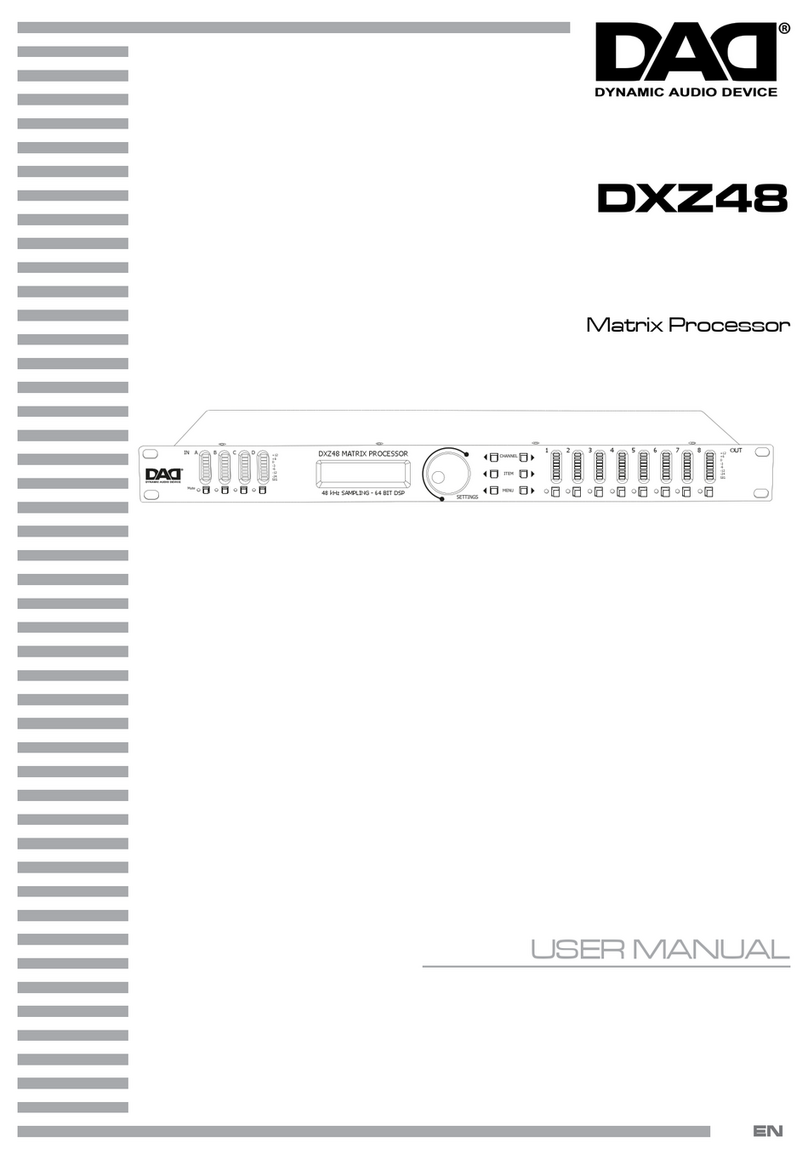
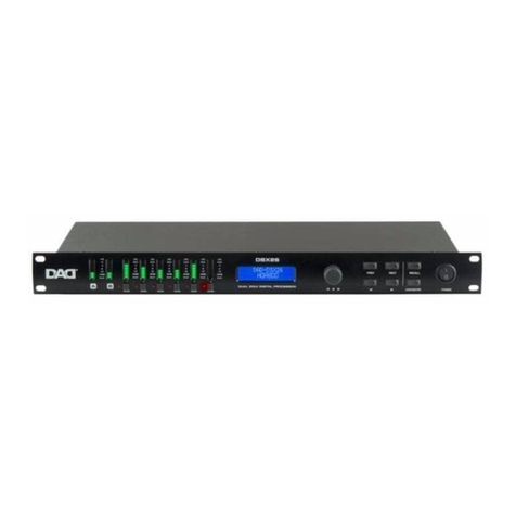
DAD DPX2060 User manual

MANUALE UTENTE
USER MANUAL
DPX2060
DIGITAL PROCESSOR
IT - EN

REV.001-04/14
Music & Lights S.r.l. si riserva ogni diritto di elaborazione in qualsiasi forma delle presenti istruzioni per l’uso.
La riproduzione - anche parziale - per propri scopi commerciali è vietata.
Al fine di migliorare la qualità dei prodotti, la Music&Lights S.r.l. si riserva la facoltà di modificare, in
qualunque momento e senza preavviso, le specifiche menzionate nel presente manuale di istruzioni.
Tutte le revisioni e gli aggiornamenti sono disponibili nella sezione 'Manuali' sul sito www.musiclights.it
All rights reserved by Music & Lights S.r.l. No part of this instruction manual may be
reproduced in any form or by any means for any commercial use.
In order to improve the quality of products, Music&Lights S.r.l. reserves the right to modify the
characteristics stated in this instruction manual at any time and without prior notice.
All revisions and updates are available in the ‘manuals’ section on site www.musiclights.it

3
DPX2060 ENIT
INDEX
Safety
General instruction
Warning and precautions for fixtures
General information
1 Descrizione e specifiche tecniche
1. 1 Specifications
1. 2 Operating elements and connections
2 Operations
2. 1 Starting up
2. 2 Selecting a Factory Preset
2.3 Parameters
2.4 Navigation
2.5 Presets
2.6 Preset Recall
2.7 Preset Store
3 DSP processing layout
3. 1 Stereo / mono formats
3. 2 Input channels
3. 3 Output channels
3. 4 Utilities
4 EQ and filter response graphs
5 Technical specifications
6 Factory presets
Warranty
INDICE
Sicurezza
Avvertenze generali
Attenzioni e precauzioni per l’installazione
Informazioni generali
1 Descrizione
1.1 Caratteristiche tecniche
1.2 Elementi di comando e collegamenti
2 Operazioni di base
2. 1 Accensione
2. 2 Selezionare i Factory Preset
2.3 Parametri
2.4 Navigazione
2.5 Preset
2.6 Richiamo dei preset
2.7 Memorizzazione dei preset
3 Struttura DSP
3. 1 Formati stereo / mono
3. 2 Canali di ingresso
3. 3 Canali di uscita
3. 4 Personalizzazione
4 Grafici di EQ e risposta del filtro
5 Specifiche tecniche
6 Preset di fabbrica
Certificato di garanzia
4
5
6
7
8
12
12
12
13
14
14
15
16
17
19
22
23
25
26
4
5
6
7
8
12
12
12
13
14
14
15
16
17
19
22
23
25
26
• DPX2060
• Cavo di alimentazione
• Manuale utente
Contenuto dell'imballo:
• DPX2060
• Power cord
• User manual
Packing content:

4DPX2060 ENIT
Before carrying out any operations with the unit,
carefully read this instruction manual, and keep it
with cure for future reference.
It contains important information about the
installation, usage and maintenance of the unit.
SAFETY
General instruction
• The products referred to in this manual con-
form to the European Community Directives
and are therefore marked with .
• The unit is supplied with hazardous network
voltage (230V~). Leave servicing to skilled
personnel only. Never make any modifica-
tions on the unit not described in this in-
struction manual, otherwise you will risk an
electric shock.
• Connection must be made to a power supply
system fitted with efficient earthing (Class I
appliance according to standard EN 60598-
1). It is, moreover, recommended to protect
the supply lines of the units from indirect
contact and/or shorting to earth by using ap-
propriately sized residual current devices.
• The connection to the main network of elec-
tric distribution must be carried out by a
qualified electrical installer. Check that the
main frequency and voltage correspond to
those for which the unit is designed as given
on the electrical data label.
• This unit is not for home use, only profes-
sional applications.
• Never use the fixture under the following
conditions:
-- in places subject to excessive humidity;
-- in places subject to vibrations or bumps;
-- in places with temperature above 45°C or
below 2°C.
• Make certain that no inflammable liquids,
water or metal objects enter the fixture.
• Do not dismantle or modify the fixture.
• All work must always be carried out by quali-
fied technical personnel. Contact the nearest
sales point for an inspection or contact the
manufacturer directly.
• If the unit is to be put out of operation defini-
SICUREZZA
Avvertenze generali
• I prodotti a cui questo manuale si riferisce sono
conformi alle Direttive della Comunità Euro-
pea e pertanto recano la sigla .
• Il dispositivo funziona con pericolosa tensione
di rete 230V~. Non intervenire mai al suo in-
terno al di fuori delle operazioni descritte nel
presente manuale; esiste il pericolo di una sca-
rica elettrica.
• È obbligatorio effettuare il collegamento ad
un impianto di alimentazione dotato di un’ef-
ficiente messa a terra (apparecchio di Classe I
secondo norma EN 60598-1). Si raccomanda,
inoltre, di proteggere le linee di alimentazione
delle unità dai contatti indiretti e/o cortocircui-
ti verso massa tramite l’uso di interruttori diffe-
renziali opportunamente dimensionati.
• Le operazioni di collegamento alla rete di
distribuzione dell’energia elettrica devono
essere effettuate da un installatore elettrico
qualificato. Verificare che frequenza e tensione
della rete corrispondono alla frequenza ed alla
tensione per cui l’unità è predisposta, indicate
sulla targhetta dei dati elettrici.
• L’unità non per uso domestico, solo per uso
professionale.
• Evitare di utilizzare l’unità:
- in luoghi soggetti ad eccessiva umidità;
- in luoghi soggetti a vibrazioni, o a possibili
urti;
- in luoghi a temperatura superiore ai 45°C o
inferiori a 2°C.
• Evitare che nell’unità penetrino liquidi infiam-
mabili, acqua o oggetti metallici.
• Non smontare e non apportare modifiche
all’unità.
• Tutti gli interventi devono essere sempre e
solo effettuati da personale tecnico qualifica-
to. Rivolgersi al più vicino centro di assistenza
WARNING!
Prima di effettuare qualsiasi operazione con
l’unità, leggere con attenzione questo manuale
e conservarlo accuratamente per riferimenti
futuri. Contiene informazioni importanti riguardo
l’installazione, l’uso e la manutenzione dell’unità.
ATTENZIONE!

5
DPX2060 ENIT
tecnica autorizzato.
• Se si desidera eliminare il dispositivo definiti-
vamente, consegnarlo per lo smaltimento
ad un’istituzione locale per il riciclaggio.
Attenzioni e precauzioni per l’installazione
• Questo prodotto in combinazione con alto-
parlanti può essere capace di produrre livelli
sonori che possono causare perdite d’udito
permanenti. Si raccomanda di evitare l’esposi-
zione ad alti livelli sonori o livelli non conforte-
voli per periodi di tempo lunghi.
• Evitare di installare l’unità in prossimità di fonti
di calore.
• Se il dispositivo dovesse trovarsi ad operare
in condizioni differenti da quelle descritte nel
presente manuale, potrebbero verificarsi dei
danni; in tal caso la garanzia verrebbe a deca-
dere. Inoltre, ogni altra operazione potrebbe
provocare cortocircuiti, incendi, scosse elettri-
che, rotture ect.
• Collocare o posizionare il prodotto in modo
che non ci siano ostruzioni alla sua propria
ventilazione e dissipazione di calore. Non in-
stallare in uno spazio limitato.
• Non collegare l’uscita di un processore nell’en-
trata di un altro. Non collegare in serie o in pa-
rallelo le uscite di un processore con quelle di
un altro.
• Spegnere il processore prima di disconnettere
il cavo di alimentazione dalla rete.
• Prima di iniziare qualsiasi operazione di manu-
tenzione o pulizia disconnettere l’unità dalla
rete di alimentazione.
tively, take it to a local recycling plant for a dis-
posal which is not harmful to the environment.
Warnings and installation for fixtures
• This product in combination with loudspeak-
ers, may be capable of producing dangerous
sound levels that could cause permanent
hearing loss. Do not operate for a long period
of time at high volume level or at a level that is
uncomfor able.
• Do not install the fixture near sources of heat.
• If this device will be operated in any way differ-
ent to the one described in this manual, it may
suffer damages and the guarantee becomes
void. Furthermore, any other operation may
lead to dangers like short circuit, burns, elec-
tric shock, ect.
• The fixture must be located in a place where a
proper ventilation or thermal dissipation is not
impeded. Do not install the fixture in a con-
fined space.
• Do not link the output of any processor chan-
nel back into another channel ‘s input. Do not
parallel or series connect an processor’s out-
put with any other processor’s output.
• Please turn off the power switch before pulling
off the power cord.
• Before starting any maintenance work or
cleaning the unit, cut off power from the main
supply.

6DPX2060 ENIT
INFORMAZIONI GENERALI
Spedizioni e reclami
Le merci sono vendute “franco nostra sede” e
viaggiano sempre a rischio e pericolo del distri-
butore/cliente. Eventuali avarie e danni dovran-
no essere contestati al vettore. Ogni reclamo
per imballi manomessi dovrà essere inoltrato
entro 8 giorni dal ricevimento della merce.
Garanzie e resi
Il prodotto è coperto da garanzia in base alle
vigenti normative.
Sul sito www.musiclights.it è possibile consul-
tare il testo integrale delle “Condizioni Generali
di Garanzia”. Si prega, dopo l’acquisto, di pro-
cedere alla registrazione del prodotto sul sito
www.musiclights.it.
In alternativa il prodotto può essere registrato
compilando e inviando il modulo riportato alla
fine del manuale. A tutti gli effetti la validità del-
la garanzia è avallata unicamente dalla presen-
tazione del certificato di garanzia.
Music & Lights constata tramite verifica sui resi
la difettosità dichiarata, correlata all’appropria-
to utilizzo, e l’effettiva validità della garanzia;
provvede quindi alla riparazione dei prodotti,
declinando tuttavia ogni obbligo di risarcimen-
to per danni diretti o indiretti eventualmente
derivanti dalla difettosità.
GENERAL INFORMATION
Shipments and claims
The goods are sold “ex works” and always travel
at the risk and danger of the distributor. Eventual
damage will have to be claimed to the freight
forwarder. Any claim for broken packs will have
to be forwarded within 8 days from the reception
of the goods.
Warranty and returns
The guarantee covers the fixture in compliance
with existing regulations. You can find the full
version of the“General Guarantee Conditions”on
our web site www.musiclights.it. Please remem-
ber to register the piece of equipment soon after
you purchase it, logging on www.musiclights.it.
The product can be also registered filling in and
sending the form available on your guarantee
certificate. For all purposes, the validity of the
guarantee is endorsed solely on presentation of
the guarantee certificate.
Music & Lights will verify the validity of the claim
through examination of the defect in relation to
proper use and the actual validity of the guar-
antee. Music & Lights will eventually provide
replacement or repair of the products declining,
however, any obligation of compensation for di-
rect or indirect damage resulting from faultiness.

7
DPX2060 ENIT
- 1 - DESCRIZIONE
1.1 CARATTERISTICHE TECNICHE
• DPX2060 è un processore digitale di segnale
audio dalle prestazioni elevate e di facile uti-
lizzo, dedicato al controllo sistemi audio pro-
fessionali in applicazioni live o installazioni
fisse. E’dotato di 2 ingressi e 6 canali di uscita,
per la gestione fino a 3 vie stereo o 6 vie mono
con frequenza di campionamento di 96kHz.
• DPX2060 è uno strumento professionale
dall’estrema precisione e flessibilità di con-
trollo, dispone dei settaggi di delay (400ms
input, 80ms output), polarità, equalizzazione,
guadagno e configurazione filtro cross-over.
• I filtri passa-basso e passa-alto Hardman con-
sentono tagli molto selettivi (con alte pen-
denze) senza procurare eccessive rotazioni di
fase. I filtri LF/HF shelving permettono la re-
golazione della risposta per adeguarsi a diver-
se condizioni acustiche o secondo la tipologia
dei sistemi audio impiegati.
• Le impostazioni e l’interfaccia di controllo
sono accessibili dai pulsanti sul pannello fron-
tale tramite display LCD oppure attraverso
l’applicazione software per PC. Modifiche ed
esecuzione dei presets possono essere atti-
vate in modo bilaterale con risposta istanta-
nea sia da interfaccia display che attraverso
software. E’ possibile controllare più unità di
DPX2060 contemporaneamente attraverso
l’interfaccia hardware dedicata.
• DPX2060 permette la memorizzazione di 45
presets nella propria libreria interna, ciascu-
no programmabile per la gestione di diverse
tipologie di sistemi audio. I presets sono atti-
vabili e modificabili anche mentre l’unità non
è collegata al pc.
• L’apparecchio è munito di sistema di protezio-
ne contro manomissioni o cancellazioni acci-
dentali dei presets.
- 1 - DESCRIPTION
1.1 SPECIFICATIONS
• DAD DPX2060 is a digital processor designed
to control PA systems in touring applications
or in fixed installations, featuring 2 Input and
6 Output channels, 32-bit (40-bit extended)
floating point processor and high-perform-
ance 24-bit analog converters.
• High resolution DSP (Digital Signal Processor)
prevents noise and distortion due to trunca-
tion errors typical of ordinary 24-bit fixed-
point devices.
• DPX2060 has a wide range of controls, includ-
ing In/Out levels, delay, polarity, 6 bands of
parametric equalizer per channel, selection
through more crossover slopes, advanced
limiter adjustment (attack/release time trig-
gering).
• 1Hz resolution allows more accurate control
over frequency.
• Input and Output channels can be routed
in multiple configurations, allowing stereo,
mono or“distribution mixer” modes.
• DPX2060 can be setup and programmed in
real-time through the front panel or the Win-
dows-compatible software accessed via USB
interface. Ethernet interface (optional) allows
connection and control of more units in larger
installations, supported by the software con-
trolling up to 16 units.
• New software and firmware upgrades can be
downloaded into DPX2060 to keep it updated
with new algorithms and functions.
• DPX2060 has several options allowing ad-
vanced protection and locking of settings and
programs.
• Internal memory saves up to 30 presets which
can then be recalled and stored from/to com-
puter hard-drive.

8DPX2060 ENIT
1.2 Elementi di comando e collegamenti 1.2 Operating elements and connections
Fig.1
Indicatori del segnale d’ingresso
Un set di tre paia di LED indica: presenza di se-
gnale, +4dBu e clip in input, per ogni canale. Il
LED di presenza di segnale opera approssimati-
vamente a -40 dBu, dando un’utile indicazione
di segnali anche deboli. Il LED +4 dBu mostra il
livello operativo nominale e può anche essere
utile per regolare il gain di sistema. I LED avver-
tono l’utente di un overload in input e operano
a 19 dBu.
Store e recall dei preset
Questi controlli danno accesso ai 45 preset re-
gistrati nell’unità. Il pulsante Store permette
all’utente di selezionare in quale locazione di me-
moria sarà salvato il preset e impostare un nome
per il nuovo preset. La funzione Recall permette
di richiamare un preset. Si noti che i preset non
possono essere registrati o richiamati in modalità
SECURE.
Manopola encoder
Tre manopole sensibili alla velocità sono usati
per regolare i parametri mostrati sul display. Fino
a tre parametri sono mostrati sul display. Il nome
del parametro è mostrato con il suo valore sotto. I
parametri sono raggruppati secondo la funzione.
Per esempio, la pagina relativa all’equalizzazione
parametrica mostra frequenza centrale, ampiez-
za e gain. Girando la manopola in senso orario, si
aumenta il valore del parametro, mentre in senso
antiorario lo si diminuisce. Girando la manopola
rapidamente si accelera la variazione del para-
Input Signal Indicators
A set of three pairs of LEDs indicate signal
present, +4dBu and input Clip for each channel.
The signal present LEDs operate at approximate-
ly -40 dBu, giving a useful indication of even rela-
tively low input signal levels.The +4 dBu LEDs are
intended to show nominal operating level and
can also be useful for setting system gain struc-
ture. Clip LEDs warn the user of input overload
and operate at +19 dBu.
Preset Store and Recall
These controls provide access to the 45 presets
stored within the device. Pressing the store but-
ton allows the user to name a preset and choose
which memory location it will be held in. Press-
ing the recall button allows the user to select
which preset they require. Note that presets can-
not be stored or recalled when Secure mode is
activated.
Parameter Knobs
Three velocity sensitive parameter knobs are
used to adjust parameters shown on the display.
Up to three parameters at a time are displayed on
the screen. The parameter name is shown above
the parameter value in each of the three screen
sec ions. The parameter knobs have a fixed as-
sociation with the screen sections; the rightmost
parameter knob adjusts the rightmost para eter
and so on.
Front panel

9
DPX2060 ENIT
metro.
Indicazioni di Output Signal / Limiter
Due LED sono disponibili per ogni canale in ou-
tput. Questi mostrano il livello di segnale relati-
vo alla soglia del limiter. Il LED giallo si accende
quando il segnale è 6 dB sotto la soglia, mentre il
LED rosso si accenderà quando la soglia del limi-
ter è stata raggiunta.
Pulsante Mute
Gli indicatori vicino ai pulsanti Mute indicano il
loro stato attuale. Premendo il pulsante si passa
da on a off.
Nota: i pulsanti mute non funzionano quando il
mode SECURE è attivato.
Pulsante Secure
Un pulsante è inserito dietro il pannello poste-
riore, tra l’output XLR e la porta RS232. Quando
attivato, questo disattiverà tutti i controlli del
pannello frontale, rendendo sicura l’unità contro
modif che accidentali.
Anche in modo SECURE, gli indicatori operano
comunque normalmente. Nota: le porte di co-
municazione sono attive in modalità SECURE.
Display (2 x 24 character LCD)
Lo schermo LCD mostra informazioni sui para-
metri dei presets.
La schermata di default mostrata dopo l’accen-
sione indica il numero e il nome del preset cor-
rente sulla riga inferiore.
Usando i knobs e i pulsanti è possibile visualizza-
re le altre informazioni.
Pulsanti di selezione canali
L’input o output attualmente selezionato è mo-
strato nell’angolo in alto a sinistra del display.
Premendo i pulsanti di selezione canale si può
navigare attraverso gli input e output disponibili
per passare poi attraverso le utilities e ritornare
alla schermata di default. Se lo stereo link è ope-
rativo, viene indicata la coppia di canali.
Per esempio channel‘1+3’ significa che si stanno
osservando i parametri dell’output 1 e 3.
Pulsanti di selezione parametro
Il nome della pagina di parametri da modificare è
mostrato nella parte a sinistra in basso dell’LCD.
Output Signal / Limiter Indication
Two LEDs are provided for each output channel.
These show the signal level related to the lim-
iter threshold. The yellow LED will light up when
the signal is 6 dB below the threshold, while the
red warning LED will light up when the limiter
threshold is reached.
Mute Buttons and Status LEDs
Each output has a Mute button and associated
mute status LED. Pressing the button turns the
mute on and off.
Note that the mute buttons do not function
when the Secure mode is activated.
Secure Button
A momentary button is fitted behind the rear
panel, between the output XLR and the RS232
port. When activated, this will disable all the front
panel controls so they cannot affect the signal
path, making the unit secure against tampering.
When in secure mode, the indicators still operate
normally. Note that the communications port is
still active in Secure mode.
Text Display
Preset parameters are shown on the 2 x 24 char-
acter text display. In most screens the currently
selected channel is displayed on the upper line
and the edit parameter on the lower line. To sim-
plify the display and enhance safety, some pa-
rameters or parameter pages are omitted when
not relevant.
Channel Select Buttons
The currently selected channel is displayed on
the top left hand corner of the LCD. Pressing the
channel buttons scrolls through the available in-
put and output channels and finally through the
utility functions and back to the default screen.
If operating a stereo linked preset, the channel
name will indicate the channel pairing.
For example ‘A+B’ means both input A and B pa-
rameters.
Edit Parameters Select Buttons
The currently selected edit parameter page is
displayed on the bottom left corner of the LCD.

10 DPX2060 ENIT
Connessione dell’alimentazione
I processori DAD devono essere connessi all’ali-
mentazione usando il cavo fornito.
Il processore ha una alimentazione in modalità
switch capace di operare da 85 V a 240 V, 50/60
Hz, adattandosi alla tensione di ingresso in modo
automatico.
Porta per DPX2060
Questa è la porta RJ45 per il controllo remoto di
altri dispositivi in rete (DAD); il tutto da un unico
PC esterno grazie al software Network Controller.
Connettori Audio Input
Tutte le connessioni audio sono bilanciate, il ca-
blaggio è il seguente: pin 1 massa, pin 2 caldo (+),
pin 3 freddo (-).
I due input hanno il pin 1 connesso direttamente
al telaio e costituiscono l’input della catena DSP.
Se si usa una sorgente sbilanciata, un ponticello
deve essere usato tra il pin 3 e il pin di massa del
cavo sbilanciato.
Connettori Audio Output
Gli output processati presentano un segnale bi-
lanciato: pin 1 massa, pin 2 caldo (+) e pin 3 fred-
do (-). Un dispositivo con ingresso sbilanciato,
può essere pilotato dal processore, collegando
il pin 3 (-) (dell’uscita del processore) alla massa
Power Inlet
The DAD units should be connected to a suitable
mains electricity supply using the cable supplied.
The processor has a switch mode power sup-
ply that is capable of operating with a nominal
mains voltage of 85V to 240V, 50/60Hz without
re-configuration.
DPX2060 Port
This is the port - with RJ45 connection - for the
remote controlling of a network with many other
devices (DAD); everything is done from only one
external PC using the software Network Contol-
ler.
Audio Input Connectors
All audio connections are fully balanced and
wired pin-1 ground, pin-2 hot & pin-3 cold. The
two inputs have pin-1 connected directly to the
chassis and supply the signal processing chains.
If an unbalanced source is used, a connection
should be made between the pin-3 ‘cold’ signal
and the ground connection of the unbalanced
source.
Audio Output Connectors
The processed outputs are impedance balanced,
and wired pin-1 ground, pin-2 hot and pin-3 cold.
An unbalanced input may be driven by connect-
ing pin-3 ‘cold’ signal to the ground connection
of the unbalanced destination input.
Fig.2Rear panel
Premendo i pulsanti Parameter si naviga attra-
verso le pagine di parametri disponibili per l’in-
put o l’output selezionato.
Pressing the edit select buttons moves through
the available parameters for the current input or
output.

11
DPX2060 ENIT
del segnale d’ingresso del dispositivo di destina-
zione.
Connettori per le porte di comunicazione
I processori DAD possono essere interamente
controllati, uno alla volta, via PC tramite il softwa-
re Network Controller.
La connessione sarà normalmente fatta attra-
verso il connettore della porta seriale (RS232).
Questa porta è anche utilizzata per l’upgrade del
firmware.
Nota: le porte di comunicazione sono attive an-
che in modalità SECURE.
Expansion Port and Serial Comms Port
DAD controllers may be controlled - one by one -
entirely from another device, typically a Personal
Computer, running an application that is compli-
ant with the ObCom standard: the Network Con-
troller. Connection will normally be made to the
controller via this serial port connector (RS232).
This port is also used for updating
the firmware in the unit. Note that the commu-
nications port is NOT disabled when the front
panel is made secure using the Secure button.

12 DPX2060 ENIT
- 2 - OPERAZIONI DI BASE
2.1 Accensione
L’unità si accenderà non appena collegata all’ali-
mentazione. Non è previsto alcun interruttore di
accensione. Durante il processo di accensione, il
numero e il modello dell’applicazione firmware
sono mostrate sull’LCD e gli output sono in mute
finché l’unità non ha terminato i controlli interni.
Una volta che le routines di start up sono state
completate, l’unità è pronta per il trattamento
del segnale audio. Il DSP sarà automaticamente
riconfigurato con i settings presenti al momento
del precedente spegnimento.
2.2 Selezionare i Factory Preset
I controllers DAD possono avere, su richiesta,
una libreria di preset di fabbrica progettati per
adattarsi a una varietà di applicazioni. I presets di
fabbrica contengono alcuni parametri che sono
fissati e nascosti all’utente. Tutti gli altri parame-
tri sono disponibili per i cambiamenti disposti
dall’utente. Il numero e il tipo di parametri fissati
e nascosti dipendono dal preset di fabbrica.
2.3 Parametri
Molti degli elementi di processo in ogni input e
output hanno caratteristiche che possono essere
controllate come gain, frequenza centrale o so-
glia del limitatore.
- 2 - OPERATIONS
2.1 Starting up
The unit will energise as soon as power is applied
to the IEC inlet; there is no power switch. During
the start up process the firmware application
model and version numbers are displayed and
the outputs are muted until the unit has com-
pleted its internal checks. Once the start-up rou-
tines are complete, the unit is ready to pass the
audio signal. The DSP signal path will be restored
to the same settings as when it was last powered
down.
2.2 Selecting a Factory Preset
The DAD controllers may have, on request, a li-
brary of Factory Presets designed to suit a range
of applications.
Factory Presets contain some parameters that
are fixed and hidden from view. The remainder
of the DSP parameters are available for user ma-
nipulation. The number and type of hidden pa-
rameters is dependant on the Factory Preset.
2.3Parameters
Many of the processing elements in each input
and output path have features that may be con-
trolled by the user, such as gain, frequency or
limiter threshold. We call these adjustable fea-
tures parameters.
Fig.3

13
DPX2060 ENIT
Un parametro può essere modificato utilizzando
uno dei tre knobs di modifica parametro (vedi
par. 3.3).
Ognuno dei tre encoder è associato ad una zona
specifica del display: l’encoder “A” agirà sul para-
metro audio presente nella zona A, e così analo-
gamente per B e C.
L’azione in senso orario incrementa il valore del
parametro, e viceversa.
Gli encoder sono sensibili alla velocità, quindi
un’azione veloce su di essi darà variazioni più ra-
pide dei valori corrispondenti.
Nei preset di fabbrica già inclusi nel processore,
quando presenti, o nei preset forniti dalla fab-
brica in forma di file e caricati sul processore
dall’utente, alcuni o tutti i parametri audio pos-
sono essere bloccati, a discrezione della fabbrica
stessa, e quindi non visibili ne modificabili.
2.4 Navigazione
I parametri del DSP sono organizzati per canali. Il
canale co rentemente selezionato è evidenziato
nell’angolo in alto a sinistra del display.
Mediante i tasti Channel è possibile navigare at-
traverso i vari canali: in particolare si evidenzia-
no, nell’ordine, tutti i canali di ingresso e uscita, le
utilities, e infine la schermata principale, in modo
circolare o avanti-indietro.
Se si sta usando un preset di tipo stereo, questo
risulterà chiaramente nella navigazione, perché i
canali d’ingresso e uscita sono appaiati a due a
due.
I tasti Parameters consentono di navigare all’in-
terno delle varie pagine di parametri disponibili
per ogni canale.
Nell’angolo in basso a sinistra appare il nome
della pagina di parametri correntemente visua-
lizzata (ciò è omesso in alcune pagine in cui la
funzione dei parametri è ovvia).
Le pagine contengono un massimo di 3 parame-
tri, modificabili come già specificato attraverso
gli encoder A, B e C.
I tasti Parameters permettono di spostarsi su tut-
te le pagine di parametri in un ordine prestabili-
to, per poi tornare alla pagina principale.
A parameter may be adjusted when it is dis-
played by turning one of the three-parameter
knobs (see par. 3.3).
Each of the three-parameter knobs is associated
with a zone on the display.
Adjusting the leftmost parameter knob will
change the value of the parameter showing in
the leftmost zone of the display and so on.
Turn a knob clockwise to increase the value of a
parameter, or anti-clockwise to decrease it.
The knobs are velocity sensitive, so turning a
knob rapidly will cause the action to ‘accelerate’,
so the value changes more rapidly.
In the factory presets that are stored in the con-
trollers (or delivered by DAD Audio) somo pa-
rameters might be hidden.
2.4 Navigation
The DSP parameters are organized by channel.
The currently selected channel is shown in the
top left hand corner of the display.
You can navigate between the channels by press-
ing the channel buttons. Pressing the channel
buttons will scroll through the channels, utilities
and back to the default screen.
When using a Preset that is stereo linked, the
channel selection will reflect this.
For example ‘1&4’ indicates outputs 1 and 4.
When navigating onto an output channel, the
usage of the output, as defined in the Preset, will
be shown briefly at the top of the screen.
Pressing the edit navigation buttons gives access
to the various pages of parameters available for
each channel.
The currently selected page is shown in the bot-
tom left hand corner of the display (this is omit-
ted on some pages where the function is obvi-
ous).
The screen shows up to three parameters for a
given part of the processing functions on a given
channel.
The edit buttons allow you to scroll, in either di-
rection, through the different processing pages
for a given channel.

14 DPX2060 ENIT
La pressione dei tasti Channel permette, come
già detto, di navigare attraverso i diversi cana-
li: ciò viene fatto mantenendo visualizzata, ove
possibile, la stessa pagina di parametri. Ad es., se
si sta modificando la pagina di parametri EQ1 sul
canale 1 e si passa al canale due, apparirà diretta-
mente la pagina EQ1 del canale d’uscita 2. Qua-
lora il nuovo canale non contempli quella stessa
pagina di parametri, verrà visualizzata quella suc-
cessiva. Nota: quando l’unità viene accesa, essa
conserva lo stesso stato dell’ultima volta in cui è
stata spenta.
2.5 Preset
I controller DAD dispongono di 45 user o facto-
ry preset; l’utente non può sovrascrivere i preset
mono o stereo di base.
2.6 Richiamo dei preset
Per richiamare un preset, premere il tasto Recall;
il LED sopra di esso si illuminerà.
Ruotare l’encoder A fino a evidenziare il preset
desiderato.
Premere nuovamente il tasto Recall per attivare
il preset evidenziato, o qualsiasi altro tasto per
annullare l’operazione.
When you go past the last page, you will be re-
turned to the default page.
The Channel buttons allow you to scroll, in ei-
ther direction, through the input and output
channels, whilst trying to maintain the currently
viewed processing block. If the channel you scroll
to does not have the currently viewed processing
block, the next one will be shown instead.
Note: when the unit powers up, the settings will
be the same as those when the unit was last
switched off.
2.5 Presets
The DAD devices contain a total of 45 user and
factory presets. The user cannot overwrite the
basic mono or stereo Preset programs.
2.6 Preset Recall
To select an existing preset, press the Recall but-
ton so the indicator above it illuminates. Turn pa-
rameter knob A until the required preset number
is shown on the display. Factory presets are indi-
cated by a box symbol appearing after the preset
number. Press the Recall button again to activate
the preset. Pressing any otherbutton will cancel
the operation.
Fig.5
Fig.4

15
DPX2060 ENIT
Fig.6
2.7 Memorizzazione dei preset
Per memorizzare lo stato corrente in un preset,
premere il tasto Store; il LED sopra di esso si illu-
minerà. Ruotare l’encoder A fino a evidenziare la
locazione di memoria desiderata. Si può inserire
il nome desiderato mediante gli encoder B e C.
Premere il tasto Store per completare l’operazio-
ne o qualsiasi altro tasto per annu larla.
Gli eventuali preset di fabbrica il cui nome si pre-
senta nella schermata principale con un piccolo
quadrato a lato sono protetti, ovvero non è pos-
sibile sovrascrivervi (anche se è possibile modifi-
care i parametri audio visibili al loro interno du-
rante la performance). Se si tenta di sovrascrivere
il preset appare un messaggio di divieto.
2.7 Preset Store
To store the current preset in a user location,
press the Preset Store Button so the indicator
above it illuminates. Turn the first parameter
knob until the required Preset location number
is show on the display.
A Preset name of up to 12 characters in length
can be entered using parameter knobs B and C.
Pressing the Store Button again completes the
process and stores the preset. As with Preset Re-
call, pressing any other button cancels the opera-
tion. The user can overwrite non-protected pre-
sets only; if an attempt is made to save a preset in
a location already occupied by a Factory Preset a
‘LOCKED PRESET’ message is displayed.

16 DPX2060 ENIT
- 3 - STRUTTURA DSP - 3 - DSP PROCESSING LAYOUT
3.1 Formati Stereo / Mono
È presente una sola struttura standard dei bloc-
chi di processamento del segnale, ma un routing
flessibile e un controllo dell’interconnessione dei
singoli blocchi permette di adattare questa strut-
tura a una grande varietà di applicazioni.
Si può lavorare nei due formati mono e stereo.
Con il formato mono, tutti gli output hanno delle
caratteristiche uniche, ma sono identici in termi-
ni di funzioni di processamento e capacità di rou-
ting. Questo è il formato più flessibile.
Il formato stereo accoppia input e output per
operare in stereo; i parametri di ogni segnale
della coppia sono identici. Il routing degli input
verso gli output è fisso. Questo formato è inteso
per operazioni stereo simmetriche, eliminando la
necessità di un setting dedicato ad ogni canale
della coppia stereo.
L’accoppiamento dei canali è il seguente:
Fig.7
3.1 Stereo / Mono Formats
There is only one standard layout of the process-
ing blocks, but flexible routing and control link-
ing allows this layout to be adapted to a wide
variety of applications.
There are two formats: Mono or Stereo. With the
Mono format, all outputs have unique parameter
settings, and all outputs are identical in terms of
processing functions and routing capability. This
is the most flexible format.
Stereo format pairs the inputs and outputs for
stereo operation, the parameters of each mem-
ber of the pair being identical. The routing of in-
puts to outputs is fixed. This format is intended
for symmetrical stereo operation, eliminating the
need to make identical parameter adjustments
for each channel.
The channel pairing is:
• Left and Right Inputs.

17
DPX2060 ENIT
• Input Left e Right.
• Output 1 (connesso all’input A) e 3 (connes-
so all’input B).
• Output 2 (connesso all’input A) e 4 (connes-
so all’input B).
• Output 3 (connesso all’input A) e 6 (connes-
so all’input B).
3.2 Canali di ingresso
Guadagno
• Knob A: Guadagno, regolabile a passi di 0.2
dB da –80 dB a +20 dB.
Delay
• Knob A: Delay, regolabile a passi da 0 a 400
ms.
Il parametro delay è finemente regolabile per
bassi valori di ritardo; la regolazione diventa
meno precisa all’aumentare del valore di ritar-
do. Il knob di parametro (sensibile alla velocità)
fornisce sia una regolazione precisa dei delay (ti-
picamente sotto i 10 ms) per compensare gli sf
samenti dei trasduttori, che una regolazione più
rapida, ma meno precisa, al fine di allineare i dif-
fusori distanti tra loro.
High Pass Filter
• Outputs 1 (routed from A input) and 3 (rout-
ed from B input).
• Outputs 2 (routed from A input) and 4 (rout-
ed from B input).
• Outputs 3 (routed from A input) and 6 (rout-
ed from B input).
3.2 Input Channels
Gain
• Knob A: Gain, adjustable in 0.2 dB steps
from –80 dB to +20 dB.
Delay
• Knob A: Delay, adjustable in variable steps
from 0 to 400 ms.
The delay parameter is adjustable in fine steps
at low values; the adjustment becomes progres-
sively coarser as the value increases. The veloc-
ity sensitive Parameter Knobs therefore provide
accurate setting of driver offset delays (typically
below 10 ms) and rapid setting of longer system
alignment delays.
High Pass Filter
Fig.8
Fig.9

18 DPX2060 ENIT
• Knob A: Frequenza, da 20 Hz a 25.6 kHz.
• Knob B: tipo di filtro passa-alto.
Sul segnale di ingresso, un filtraggio passa-alto
del segnale è disponibile. Questa è la posizione
ottimale per il filtro passa-alto poiché interessa
tutti gli output e può quindi migliorare le rela-
zioni di fase interbanda. Il tipo di filtro è selezio-
nabile tra Butterworth, Bessel, Linkwitz-Riley e
Hardman. Le pendenze del filtro sono disponibili
fino al quarto ordine o 24 dB/ottava. Non tutti i
tipi di filtro sono disponibili per tutte le penden-
ze. Per esempio, filtri 18 dB/ ottava Linkwitz-Riley
non esistono. Il filtro di tipo Hardman è sempre
descritto dal suo ordine poiché la pendenza del
filtro diventa progressivamente sempre più ripi-
da cosicché una descrizione in dB/ottave non è
applicabile.
Equalizzazione parametrica
Sono possibili 8 equalizzazioni parametriche, 2
filtri di shelving e 6 sezioni parametriche com-
pletamente controllabili.
Filtri di shelving High e Low
• Knob A: Frequenza di transizione, da 10 Hz a
25.6 kHz, in passi variabili.
• Knob B: Pendenza, da 6 a 12 dB/ottava, in
passi da 1 dB.
• Knob C: Gain, +/-15 dB, in passi di 0.2 dB.
• Knob A: Frequency, from 20.0 Hz to 25.6
kHz, in variable steps.
• Knob B: High pass filter type.
System high pass filtering is provided for the in-
put signal. This is the preferred location for high
pass filtering as it affects all outputs and can
therefore improve inter-band phase relation-
ships. Filter type is selectable from Butterworth,
Bessel, Linkwitz-Riley and Hardman. Filter slopes
of up to 4th order or 24dB / octave are provided.
Not all filter types are available in all slopes. For
example 18dB / octave Linkwitz-Riley filters do
not exist. The Hardman type filter is always de-
scribed by its order as the filter becomes progres-
sively steeper rather than following a linear slope
so a dB/octave description is not accurate.
Parametric Equalisation
Eight sections of equalisation are provided, two
shelving filters and
six fully variable parametric sections.
High and Low shelving filters
• Knob A: Transition Frequency, 10 Hz - 25.6
kHz in variable steps.
• Knob B: Slope, 6 to 12dB / octave in 1dB
steps.
• Knob C: Gain, +/-15dB in 0.2dB steps.
Fig.10
Fig.11

19
DPX2060 ENIT
La frequenza è specificata come il punto dove il
filtro devia di 3 dB dal valore di guadagno.
Filtri parametrici
• Knob A: Frequenza centrale, da 10 Hz a 25.6
kHz, a passi variabili.
• Knob B: Larghezza, selezionabile da display:
Q o ottave. Oct regolabile da 0.1 a 5 ottave
a passi variabili; Q regolabile da 14.2 a 0.2 a
passi variabili.
• Knob C: Guadagno, +/-15 dB, a passi di 0.2
dB.
3.3 Canali di uscita
Gain e Polarity
• Knob A: Gain, regolabile a passi di 0.2 dB, da
–80 dB a +20 dB.
• Knob B: Polarity, selezionabile: normal o re-
versed.
Delay
The frequency is specified as point where the fi
ter deviates by 3dB from the gain value.
Parametric filters
• Knob A: Centre Frequency, 10.0 Hz - 25.6
kHz in variable steps.
• Knob B: Width, display selectable: Q or Oct
(Bandwidth). Oct adjustable from 0.1 to 5
octaves in variable steps, Q adjustable from
14.2 to 0.2 in variable steps.
• Knob C: Gain, +/-15 dB in 0.2 dB steps.
3.3 Output Channels
Gain and Polarity
• Knob A: Gain, adjustable in 0.2 dB steps
from –80 dB to +20 dB.
• Knob B: Polarity, selectable, normal or re-
versed with reference to other outputs.
Delay
Fig.12
Fig.14
Fig.13

20 DPX2060 ENIT
• Knob A: Delay, regolabile a passi variabili da
0 to 80 ms.
Come per i delay in input, la regolazione diventa
meno precisa all’aumentare del valore di ritardo.
Filtri High e Low pass
• Knob A: Frequenza di taglio, <<off, 20.0 Hz -
25.6 kHz, out>>.
• Knob B: tipo di filtro passa-basso o passa-
alto.
Il tipo di filtro è selezionabile tra Butterworth,
Bessel, Linkwitz-Riley o Hardman. Le pendenze
del filtro sono disponibili fino all’ottavo ordine o
48 dB/ottava. Il filtro di tipo Hardman è sempre
descritto dal suo ordine.
Equalizzazione parametrica
Come per la sezione di input, 8 sezioni di equaliz-
zazione sono possibili oltre a 2 filtri di shelving e
6 sezioni parametriche completamente control-
labili.
• Knob A: Frequenza, da 10 Hz a 25.6 kHz, a
passi variabili.
• Knob B: Slope, da 6 a 12 dB/octave, a passi
di 1 dB.
• Knob C: Gain, +/-15 dB, a passi di 0.2 dB-
La frequenza è specificata come il punto dove il
filtro devia di 3 dB dal valore di guadagno.
• Knob A: Delay, adjustable in variable steps
from 0 to 80 ms.
As for input delay, velocity sensitive Parameter
Knobs provide finer adjustment at low levels and
rapid selection of higher values.
High and Low Pass Filters
• Knob A: Cut off frequency, <<out, 20.0 Hz -
25.6 kHz, out>>.
• Knob B: High pass or low pass filter type.
Filter type is selectable from Butterworth, Bessel,
Linkwitz-Riley and Hardman. Filter slopes of up
to 8th order or 48 dB/octave are provided. The
Hardman type filter is always described by its
order.
Parametric Equalisation
Eight sections of equalisation are provided in a
similar format to the input channel equalisation;
two shelving filters and six parametric.
• Knob A: Frequency, from 10 Hz to 25.6 kHz,
in variable steps.
• Knob B: Slope, from 6 to 12 dB/octave, in 1
dB steps.
• Knob C: Gain, +/-15 dB, in 0.2 dB steps.
The frequency is specified as point where the fil-
ter deviates by 3 dB from the gain value.
Fig.16
Fig.15
Table of contents
Other DAD Computer Hardware manuals