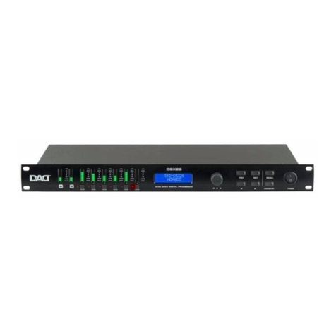
DAD DXZ48 User manual

USER MANUAL
EN
DXZ48
Matrix Processor
DXZ48 MATRIX PROCESSOR
48 kHz SAMPLING - 64 BIT DSP
IN A B C D
Mute
SETTINGS
+12
+6
0
-3
-6
-12
-24
SIG
CHANNEL
ITEM
MENU
1
2
3 4 5 6 7 8
OUT
+12
+6
0
-3
-6
-12
-24
SIG

REV.001-09/16
All rights reserved by Music & Lights S.r.l. No part of this instruction manual may be
reproduced in any form or by any means for any commercial use.
In order to improve the quality of products, Music&Lights S.r.l. reserves the right to modify the
characteristics stated in this instruction manual at any time and without prior notice.
All revisions and updates are available in the ‘manuals’ section on site www.musiclights.it

3
EN
DXZ48
CONTENTS
4
4
5
6
7
8
8
13
13
15
Safety
General instructions
Warnings and installation precautions
General information
Description and technical specications
Introduction
Operating elements and connections
Functions and settings
System setup and gain structure
Setup and operation
Maintenance
Ordinary maintenance
Maintenance and troubleshooting
Technical specication
Warranty
• DXZ48
• User manual
Packing content:

4DXZ48 EN
Before carrying out any operations with the unit, carefully read this instruction manual, and keep it with cure
for future reference.
It contains important information about the installation, usage and maintenance of the unit.
SAFETY
General instruction
• The products referred to in this manual conform to the European Community Directives and are there-
fore marked with .
• The unit is supplied with hazardous network voltage (240V). Leave servicing to skilled personnel
only. Never make any modications on the unit not described in this instruction manual, otherwise
you will risk an electric shock.
• Connection must be made to a power supply system tted with ecient earthing (Class I ap-
pliance according to standard EN 60598-1). It is, moreover, recommended to protect the supply
lines of the units from indirect contact and/or shorting to earth by using residual current devices
appropriately sized.
• The connection to the main network of electric distribution must be carried out by a quali-
ed electrical installer. Check that the main frequency and voltage correspond to those the unit is
designed for, as given on the electrical data label.
• This unit is not for home use, only professional applications.
• Never use the xture under the following conditions:
- in places subject to excessive humidity;
- in places subject to vibrations or bumps;
- in places with temperature above 45°C or below 2°C.
• Make certain that no inammable liquids, water or metal objects enter the xture.
• Do not dismantle or modify the xture.
• All work must always be carried out by qualied technical personnel. Contact the nearest
sales point for inspection or contact the manufacturer directly.
• If the unit has to be put out of operation denitively, take it to a local recycling plant for a environ-
mentally safe disposal.
Warnings and installation precautions
• This product in combination with amplier, may be capable of producing dangerous sound levels that
could cause permanent hearing loss. Do not operate for a long period of time at high volume level or
at a level that is uncomfortable.
• Do not install the xture near sources of heat.
• If this device will be operated in any way dierent to the one described in this manual, it may suer
damages and the guarantee becomes void. Furthermore, any other operation may lead to dangers like
short circuit, burns, electric shock, ect.
• The xture must be located in a place where a proper ventilation or thermal dissipation is not impeded.
Do not install the xture in a conned space.
• Do not link the output of any processor channel back into another channel ‘s input. Do not parallel
or series connect an processor’s output with any other processor’s output.
• Please turn o the power switch before pulling o the power cord.
• Before starting any maintenance work or cleaning the unit, cut o power from the main supply.
WARNING!

5
EN
DXZ48
GENERAL INFORMATION
Shipments and claims
The goods are sold “ex works” and always travel at the risk and danger of the distributor. Eventual dam-
age will have to be claimed to the freight forwarder. Any claim for broken packs will have to be forwarded
within 8 days from the reception of the goods.
Warranty and returns
The guarantee covers the xture in compliance with existing regulations. You can nd the full version of
the “General Guarantee Conditions”on our web site www.musiclights.it.
Please remember to register the piece of equipment soon after you purchase it, logging on www.musi-
clights.it. The product can be also registered lling in and sending the form available on your guarantee
certicate. For all purposes, the validity of the guarantee is endorsed solely on presentation of the guar-
antee certicate. Music & Lights will verify the validity of the claim through examination of the defect
in relation to proper use and the actual validity of the guarantee. Music & Lights will eventually provide
replacement or repair of the products declining, however, any obligation of compensation for direct or
indirect damage resulting from faultiness.
The information provided in this manual has been carefully checked. However music & lights is
not responsible for Any possible inaccuracy.

6DXZ48 EN
INTRODUCTION
Congratulations on the purchase of your DXZ48. DXZ series strives to be the best in high end digital audio
processing. After you have become familiar with your processor, we encourage you to experiment and nd the
most eective and ecient way to run your system by utilizing the powerful processing of the DXZ48.
The DXZ48 is a powerful processor with four analog inputs, eight outputs (12dBu), 10 PEQ bands per input
and output and a frequency range to 20kHz. The rugged analog input stage accepts input voltages of up to
+23dBu thus matching any source on the market today, with an excellent dynamic range of 118dB. Using a
switch-mode power supply for clean power supply rails and superior ruggedness, 64-bit digital processing and
some of the best converters available on the market today, the DXZ48 oers sound quality that sets standards
in professional as well as high-end home audio.
This User Manual describes how to operate the DXZ48’s settings via the front panel controls. Alternatively, the
DXZ48 can be congured completely via a remote connection to a PC, MAC, iPad or iPhone. Please refer to the
Software User Manual for details on the remote control application.
Controlled via the front panel or via the remote control application, the DSP settings and coecients are calcu-
lated on the y at the moment of changing the parameters. Frequencies can be set with 1Hz accuracy, delays
with 20 microseconds accuracy, and gains with 0.01dB accuracy. When editing values via the front panel, some
values are limited in granularity; e.g. gain is set via 0.25dB steps in this case.

7
EN
DXZ48
Fig.1
OPERATING ELEMENTS AND CONNECTIONS
In addition to the available features described in this manual, you also have the option of controlling the
processor remotely over your network. Please refer to the Software Manual for details.
1. POWER IN: mains plug for connection to a socket (80 to 240V 50Hz) via the supplied mains
cable. The support for the mains fuse is located under the mains plug. Only replace a blown fuse by
one of the same type. Be sure your amplier is turned o before you plug in the mains supply cable
into an electrical outlet.
2. OUTPUT 1÷8: XLR male connector with a balanced line level input. - Pin 1 = shield or ground; - Pin 2
= + positive or “hot”; - Pin 3 = - negative or“cold”.
3. NETWORK: RJ45 connector; Connect to a router/wi router with DHCP to enable automatic setup of
the IP address. Connect to a PC/switch without setting a xed IP and the unit will perform zero cong.
Setup a xed ip to the unit, you need to connect by a DHCP or zero cong network before to be able
to change the ip address.
Note: Only enable one of your network interfaces of the computer to avoid any issues.
4. INPUT A-B-C-D: XLR female connector with a balanced line level input. - Pin 1 = shield or ground; -
Pin 2 = + positive or“hot”; - Pin 3 = - negative or “cold”.
5. MUTE : press any of the front panel Mute keys to toggle the channel in and out of mute. The
button will light red when the output is muted.
6. LED OUTPUT BAROGRAPHS : the Output barographs represent signal level relative to limiter
threshold. These show the output level: SIG, -24dB, -12dB, -6dB, -3dB, 0dB (Limit), +6dB
(CLIP).
7. DISPLAY LCD.
8. THE ROTARY ENCODER: to the right of the display screen there is a continuous rotary encoder that,
when turned, changes the values in the value area of the screen. If this control is pushed in it will
step through the inputs and outputs modes. If held down and turned it will enable fast switching
through the available modes.
9. FUNCTION BUTTONS: The function buttons allow direct access to all editing and navigating functions.
See section three for a detailed description on the functions of each of these buttons.
10.MOUNTING HOLES for xing the rack.
3
5
6
789
1
10
5
6
24
80-240 VAC 2.1AT
IN A
Mute Mute
+12
+6
0
-3
-6
-12
-24
SIG
DXZ48 MATRIX PROCESSOR
48 kHz SAMPLING - 64 BIT DSP
B C D
SETTINGS
CHANNEL
ITEM
MENU
1
2
3 4 5 6 7 8
OUT
+12
+6
0
-3
-6
-12
-24
SIG

8DXZ48 EN
FUNCTIONS AND SETTINGS
SYSTEM SETUP AND GAIN STRUCTURE
This product oers a wide range of tools for sound system design and setup. These tools can make your
system more ecient and better sounding, but to get the best possible sound it is important to use these
tools properly.
The following section explains how to maximize system gain and how to use the limiters to protect your
ampliers from clipping. In traditional system design, the output of your console would be routed to a
system EQ, a compressor, and a crossover with output level control. From the crossover, there may be
additional lters that are employed to improve the response of your speakers. There may also be limiters
set up to keep
your ampliers from going into clipping and protect your speakers from the hazards of a clipped signal.
Your ampliers play a vital role in system setup, because they are last item in the chain before your speak-
ers and oer the greatest amount of gain (that is their job after all). If your limiters and ampliers are incor-
rectly setup you will not be using your system to its fullest potential and could be harming your speakers.
To ensure an optimal gain structure:
Play a signal at the nominal level from your mixing desk, and set the input gain of your processor to 0.
Set the crossovers that you want to use, while keeping the output gains also at 0.
With DISCONNECTED loudspeakers, turn up the volume of the power ampliers entirely clockwise (full
volume).
Now reduce the output gain and / or the output limiter setting to get the desired gain, so that the ampli-
er is just clipping and the built-in limiters of your processor are just limiting. If the amplier does not have
a built-in clip limiter, set your processor’s limiter so that the amplier does not clip.
Now turn down the volume of the power ampliers, connect your speakers, and slowly increase the vol-
ume while checking the sound.
If all is well, there should be distortion-free sound, and the limiter LEDs are ashing or o, but not continu-
ously on. If they are continuously on, reduce the output gain of your processor.
If you cannot reach enough signal level, increase the processor’s input gain or turn up the level from your
mixing desk.
SETUP AND OPERATION
Before plugging the processor in, always make sure that the power supply matches the product specica-
tion voltage. Install this device on a at, stable surface, not bent or curved. Do not supply power before
all components of the system are set up and connected properly. Make sure your power ampliers are
switched on last in order to avoid transients, which could damage your speakers or annoy your audience.
1 . System Check
After connecting all cables, you should mute all outputs rst or turn the gain/level setting on your ampli-
ers to minimum. Activate the HF-outputs rst. In case of wrong cabling, High Frequency (HF) audio signals
will come out of bass-speakers that cannot be harmed this way. Vice versa, the Low Frequency (LF) audio
signals would destroy your HF-speakers. It is advisable to install a large capacitor in series with HF drivers
(47 - 100 uF). That way, drivers are somewhat protected against accidental instrumentation errors.
2 . Input Setup
Press the Channel Up or Down button to select the input channel you wish to edit. Make the rst settings
with the output turned low or muted.
To toggle through the dierent items, press the Item Up or Item Down buttons.

9
EN
DXZ48
2.1 . Gain
Adjust the gain by dialing the rotary encoder. The gain is adjusted in steps of 0.25dB. Smaller steps (0.01dB)
can be set via the PC or MAC interface.
2.2 . Input Selection
Select the source (Analog) by rotating the encoder.
2.3 . Channel Link
By linking 2 channels, the settings are guaranteed to be identical for both channels, except for mixer and
mute. Turn the encoder to set the Channel Link on or o.
3 . Output Setup
Press the Channel Up or Down button to select the output channel you wish to edit. Make the rst settings
with the output turned low or muted.
To toggle through the dierent items, press the Item Up or Item Down buttons.
3.1 . Gain
Adjust the gain by dialing the rotary encoder. The gain is adjusted in steps of 0.25dB. Smaller steps (0.01dB)
can be set via the PC or MAC interface.
3.2 . Mixer
Turn the rotary encoder to mix the signal from the selected input to the selected output. Push the rotary
encoder to select the input. Attention: The mixer is only available while the outputs are not linked by
Channel Link. If the channels are linked, the mixer will be skipped.
3.3 . Delay
Set the delay time by turning the encoder. Select the displayed unit (ms or s, mm or m, feet, inches, or mils)
by pushing the encoder.

10 DXZ48 EN
3.4 . Low Pass Filter
Adjust the Low Pass Filter frequency by turning the rotary encoder. You can switch the low pass lter o by
turning the rotary encoder up (clockwise) until the frequency passes 20kHz.
Press the rotary encoder to change the lter type. Select the type by turning the rotary encoder. You can
choose from: Butterworth 6dB, Bessel 6dB, Butterworth 12dB, Bessel 12dB, Linkwitz Riley12dB, Butter-
worth 18 dB, Bessel 18dB, Butterworth 24dB and Bessel 24dB. Higher order lters may be set by adding
lter sections in the PEQ blocks (see below).
3.5 . High Pass Filter
Adjust the high pass frequency by dialing the rotary encoder. You can switch the high pass lter o by
dialing the rotary encoder down (counterclockwise) until the frequency passes 20Hz.
Press the rotary encoder to change the lter type. Select the type by turning the rotary encoder. You can
choose from: Butterworth 6dB, Bessel 6dB, Butterworth 12dB, Bessel 12dB, Linkwitz Riley12dB, Butter-
worth 18 dB, Bessel 18dB, Butterworth 24dB and Bessel 24dB. Higher order lters may be set by adding
lter sections in the PEQ blocks (see below).
3.6 . Parametric Equalizer (PEQ )
There are 10 bands of parametric equalization. Each band can be adjusted freely over the frequency range
of 20Hz to 20kHz. Adjust the frequency by dialing the rotary encoder.
Press the rotary encoder to select the parameters. The available parameters are: Frequency (20Hz to
20 kHz), Gain (-12dB to +12dB), Q (0.2 to 25), Enabled (On or O), Type (Bell, High Shelf, Low Shelf, Notch,
All Pass, Band Pass, High Pass, Low Pass). For the Shelving lters, the Q value sets the steepness of the lter
in dB/Oct.
3.7 . Limiter
The limiter is a zero-attack peak limiter. Only the threshold and release can be set. Press the rotary encoder
to select the parameters. The release value is displayed in dB per second.

11
EN
DXZ48
3.8 . Phase Inversion
Turn the rotary encoder to switch phase inversion on or o.
3.9 . Channel Link
By linking 2 channels, the settings are guaranteed to be identical for both channels, except for mixer and
mute. Turn the encoder to set the Channel Link on or o.
4 . System Menu
Push the Menu button to enter the system menu. Push the Menu button again to toggle through the
menu items. The available menu items are:
4.1 . Load Preset
Turn the rotary encoder to select the preset you wish to load. Push the rotary encoder to select it, then
turn it again to select “YES” and conrm again by pushing the rotary encoder knob. The preset is loaded
and all settings are applied immediately. All settings that were in the unit prior to loading the preset will
be erased.
This action can not be undone.
The presets contain all lter, dynamics, gain settings etc; in other words, everything that makes out a loud-
speaker conguration. Presets do NOT contain the name of the unit, network conguration, automatic
standby delay, user access rights and passwords.
4.2 . Save Preset
Turn the rotary encoder to select the location of the preset. If that location is not empty, the preset in that
location will be overwritten. This action can not be undone.
The system will ask you to give a name to the preset name. Select a character in the cursor position by
turning the rotary encoder; pushing the rotary encoder conrms the character selected and moves the
cursor to the next character to edit. Pushing the exit/ESC button erases the last conrmed character. Once
the name is set up, push the menu button again. If you want to continue storing the preset, select Yes by
turning the rotary encoder and conrm by pushing it. To cancel, push the exit button. Now your preset is
saved in the selected location.
The presets contain all lter, dynamics, gain settings etc; in other words, everything that makes out a loud-
speaker conguration. Presets do NOT contain the name of the unit, network conguration, automatic
standby delay, user access rights and passwords.
4.3 . Access Level
The DXZ48 has the option of locking away the front panel controls to avoid tampering of settings by un-
authorized persons. To lock the unit, select“Locked” by turning the rotary encoder, and push it to conrm.
The system will ask you to enter a password. Select a character in the cursor position by turning the rotary

12 DXZ48 EN
encoder; pushing the rotary encoder conrms the character selected and moves the cursor to the next
character to edit. Pushing the exit/ESC button erases the last conrmed character. Once the password is
set up, push the menu button again and the unit will be locked.
ATTENTION: Make sure to remember the password! When the unit is locked and you forgot the password,
it is not possible to unlock it without contacting your local service representative.
To unlock the unit select“Unlocked” and enter the password. The password is automatically checked after
each entered character, and the unit will exit the system menu when the password is conrmed. The de-
fault password is“Password”.
4.4 . Version Information
By pushing the rotary encoder, the display toggles through the version information about the unit (serial
number, rmware version), as well as some parameters like IP address, subnet mask, MAC address etc.

13
EN
DXZ48
Technical specication DXZ48
Product Type Matrix Processor
Input 4 way mono
Output 4 way stereo, 8 way mono
Connection Ethernet port
Dynamic range 110dB
Max Input Level +23dBu
Frequency Responce 20Hz to 20kHz
Distortion <0.01%, (+10dBu, 20Hz to 20kHz)
DSP 64 bit
Sampling rate 48 kHz
A/D - D/A Converters 24 bit
Gain OUT +12dB to -48dB and mute, 0.25dB steps
Delay output 2000ms
Crossover Filters Slope 12, 18 & 24dB/octave Bessel and Butterworth
12 & 24dB/octave Linkwitz Riley
Parametric Filters 10 for input and output: Bell, High Shelf, Low
Shelf, Notch, All Pass, Band Pass
EQ frequency 10Hz to 20kHz
EQ gain +12dB to -12dB, 0.25dB steps
EQ width Q 25 to 0.2 - BW 4.75 to 0.06
Limiter Zero-attack peak limiter
Compressor True RMS compressor. Adjustable threshold,
attack time, release, hold
Audio Connectors 3-pin XLR
Power supply 80 to 240V AC, 50/60Hz
Weight 1,7 Kg
Dimensions (WxHxD) 482x44x175mm
TECHNICAL SPECIFICATION


MUSIC & LIGHTS S.r.l.
Via Appia, km 136,200 - 04020 Itri (LT) - ITALY
Phone +39 0771 72190 - Fax +39 0771 721955
www.musiclights.it - email: info@musiclights.it
ISO 9001:2008 Certied Company
DAD è un brand di proprietà della Music & Lights S.r.l. DAD is a brand of Music & Lights S.r.l. company. ©2016 Music & Lights S.r.l.
This manual suits for next models
1
Table of contents
Other DAD Computer Hardware manuals