DAELIM ROADWIN VJ125 - SERVICE User manual

SM48-0401-01E
HEAD OFFICE (FACTORY)
#58, SUNG SAN-DONG, CHANGWON, KYUNGNAM, KOREA
TEL : (82-55) 239-7000 / FAX : (82-55) 239-7524
OVERSEAS SALES OFFICE
#13-5, SUNG SOO 1DONG 1GA, SUNG DONG GU, SEOUL, KOREA
TEL : (82-2) 498-6465 / FAX : (82-2) 467-9997

HOW TO USE THIS MANUAL
This manual describes effective maintenance procedure
for the VJ125 manufactured by DAELIM Motor Co., Ltd.
To ensure safety and optimal operating conditions of the
vehicle, carry out regular inspections according to the
maintenance schedule (Section 2).
Sections 1 through 2 provide information on overall
vehicle; and section 3 describes maintenance procedure
for the engine, frame and electrical systems.
To facilitate use of this manual, each page starts with
disassembly and system diagrams, service information,
and troubleshooting guide. If you cannot find the cause of
trouble, refer to Section 21: Troubleshooting.
Contents of this manual and specifications are
subject to change without prior notice for
improvement of vehicle quality.
No part of this publication may be reproduced
without written permission of DAELIM Motor Co.,
Ltd.,
CONTENTS
GENERAL INFORMATION
INSPECTIONS / ADJUSTMENTS
LUBRICATION
FUEL SYSTEM
ENGINE
1
2
3
4
COOLING SYSTEM
5
ENGINE REMOVAL
CLUTCH / GEARSHIFT
A.C.GENERATOR / STARTER CLUTCH
CYLINDER HEAD / VALVES
CYLINDER / PISTON
CRANKCASE / TRANSMISSION /
CRANKSHAFT
EXTERNAL PARTS
REAR WHEEL /REAR SUSPENSION
FRONT WHEEL/FRONT FORK/STEERING
HYDRAULIC BRAKE
FRAME
ELECTRICAL SYSTEM
BATTERY / CHARGING SYSTEM
ELECTRIC STARTER
LIGHTS/METER/SWITCHES
IGNITION SYSTEM
6
7
8
9
10
11
12
13
14
15
16
17
WIRING DIAGRAM
18
TROUBLESHOOTING
19
20
21


1-1
1. GENERAL INFORMATION
SERVICE INFORMATION··············1-1
SERVICE RULES····················1-1
CAUTION WHEN WIRING ··········1-5
MODEL IDENTIFICATION ··········1-9
SPECIFICATIONS ··················1-10
TORQUE VALUES··················1-12
SYMBOLS / ABBREVIATIONS ······1-14
TOOLS····························1-15
WIRING DIAGRAM ················1-16
SERVICE INFORMATION
1. Do not run the engine for a long time in closed or not well-ventilated area because the exhaust gas contains toxic
substances such as carbon monoxide, hydrocarbon, nitric oxide.
2. The battery fluid(lean sulfuric acid) is extremely toxic. It is dangerous if skin is exposed to it or if it enters into the eye.
Be careful in handling. When exposed to the battery fluid, wash it with water and get a medical check up.(store the
battery fluid in a safe place to avoid touching by the children)
3. Pay attention not to be burned and always put on the protection gears because the engine or the muffler is hot right after
engine stops.
4. Gasoline is extremely flammable. Maintenance must be performed in the place free of the open fire or electric spark.
5. When more than two person are working, always pay attention to other worker’s action and always have safety in mind.
6. The skin exposed to used engine oil can be a major reason of the skin cancer. Pay attention not to be exposed and wash
carefully with soap and water after handling.
7. If compressed air is used to clean the brake, dust scattered in the air can be breathed in by workers. Please take action not
to scatter dust in the brake cleaner, etc.
8. Flammable nitrogen gas is generated during charging the battery so charging must be performed in well-ventilated area
and free of the open fire and spark.
SERVICE RULES
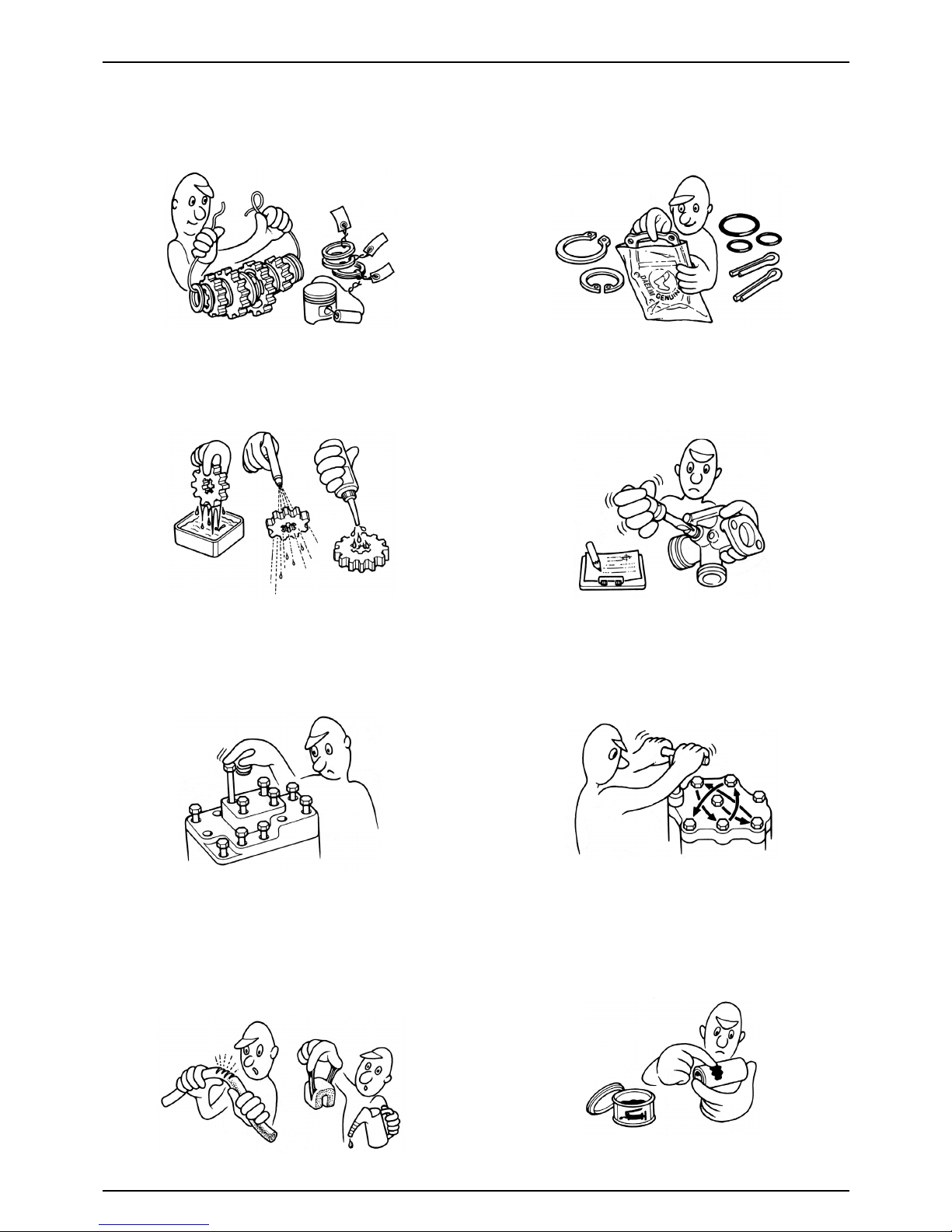
1. Parts and lubrication oil must be DAELIM genuine or
recommended parts.
2. Before maintenance, remove deposit or dust from the
chasis.
1

1-2
GENERAL INFORMATION
9. Check to see if the rubber part is worn out when
removing it and replace it if necessary. Some rubber part
is weak to gasoline and kerosene, so pay attention not to
soak with gasoline or oils.
10. Recommended grease must be applied to or filled in
the specified place.
7. Align the bolts to uniform the tightening points before
tightening them when you don’t know the bolt length.
8. Bolts, nuts and pieces must be tightened from the bigger
diameter to the smaller one, from inside to outside and
diagonally with the specified torque.
5. Clean the parts after the overhaul and before the test and
remove the cleaning oil with compressed air. Apply oil
to seal face during installation.
6. Check necessary place and measure necessary data
during installation. When installing, return to the state
before removing.
3. Store the parts of each system discriminatively to install
each part in the right place.
4. After removing gasket, O-ring, piston pin clip and cotter
pin, always replace them with the new one. When
removing the snap ring, it can be easily missed after
transformation or installation.

1-3
GENERAL INFORMATION
11. Maintenance needed to use the specialized tools must
be performed with the right tool.
12. Never reuse the ball bearing removed with the ball
applied pressure when removing press-fitted the
bearing.
13. Check the smooth rotation of inner or outer race of the
ball bearing by rotating it manually.
Replace the ball bearing having excessive axial/
longitudinal hanging.
Wipe the ball bearing likely to have hanging with
cleaning oil.(except double-sided sealed type ball
bearing)
Replace the ball bearing of which press-fitted part is
slacked at the case or shaft.
14. Pay attention to installation direction in case of the
single-sided sealed ball bearing. Install the open-
direction or double-sided sealed bearing in the way
that the face marked with manufacturer and size
should direct to the outer axle.
15. When blowing the ball bearing with compressed air
after cleaning, keep the race from rotating. High speed
rotation of the race may damage the bearing. Prior to
installation, apply oil or grease to the bearing.
16. Install the snap ring so that chamfered side directs to
the load-applied side. After installation, check the
proper installation by rotating the snap ring.
17. Check each part for proper tightening and operation
after installation.
18. The brake fluid and coolant can damage the painted
plastic or rubber parts. Keep these parts from
contacting with them and wash these parts with water
in case of contact.
’

1-4
GENERAL INFORMATION
21. Keep the pneumatic system interior or the engine
interior from the infiltration of dust.
22. Install the gasket mounted in the contact surface of
each case of the engine while removing gasket
material completely. Remove damaged contact surface
by wiping with the oil stone equally.
19. Install the oil seal so that the manufacturer marked
surface directs outer surface.(direction not covered
with oil)
Pay attention not to bend or damage the lip.
Apply the grease to the lip.
20. Connect the tube until the tube fully inserted in the
joint. Install the clip if it is supplied. Replace the tube
having slacked end.
23. Pay attention not to bend the cable excessively.
Transformed or damaged cable may cause malfunction
or damage.
24. Install the boots with the installing groove by inserting
the boots into the groove.
’

1-5
GENERAL INFORMATION
Each cord must be connected depending on its color.
When connecting different cord, attach color tube
around the connector. Connect the coupler to the
connector with same color and same pin number.
Identify the two-colored cord by main color first and
then spriped color .
When measuring voltage or resistance of the cord
terminal using tester, contact the tester plug behind of
the coupler. Pay attention not to open the cord terminal
and contact the tester plug from the front of the coupler
in case of water-proof coupler.
Recheck the condition of contact, securing and
continuity of each part after maintenance.
When connecting the battery, the plus terminal must be
connected first.
After connecting the terminal, apply the grease to the
terminal.
When disconnecting the battery, the minus terminal
must be disconnected first.
Make sure that the tool such as spanner do not contact
with the frame.
Connect covers to the terminal after maintenance.
If the fuse is short-circuited, find out the cause and
repair. Replace with the fuse having the specified
capacity.
If there is rust in the terminal, remove the rust with sand
paper prior to connecting.
CAUTION WHEN WIRING
VALIDATION
OF CAPACITY! REMOVE
THE
RUST!

1-6
GENERAL INFORMATION
Insert the lock of the coupler until the lock is fully
secured.
Turn off the main switch before connecting/dis-
connecting.
Release the lock to disconnect the lock of the coupler.
The lock of the coupler has two types according to
releasing method(press type and pull type) so release it
properly according to the shape.
- Typical releasing method of the coupler is illustrated in
the following.
When disconnecting the coupler, disconnect it while
holding the coupler body. Pull while holding the wire
harness cord and do not remove the coupler connection.
Release the lock by inserting the coupler slightly and
then narrowing connection to remove the coupler.
Pay attention not to damage the vinyl cover of the
coupler.
Check to see if there is bended terminal and secure it to
avoid disconnecting.
If the wire harness coating is damaged, repair by
winding vinyl tape or replace it.
Prior to connecting the connector, make sure that the
cover is not damaged and the mess terminal is not
opened.

1-7
GENERAL INFORMATION
Wire band must be secured firmly in the specified
location of the frame. In case of aluminium band,
secure the wire harness to the coated part.
Secure the wire harness firmly using the clamp.
Insert the connector until the vinyl cover is fully
inserted into the terminal.
The opening of the vinyl cover must face at the ground
direction but in case of the plain connector, the draining
opening must face at the sky direction.
When removing T-start, broaden the groove of T-start
using the wiring driver and release the torque.
Connect the harness and the hose to T-start and then
insert until the groove is locked.
When removing T-start from the frame, replace it with
the new one.
In case of the weld clamp, do not clamp in the welded
part.
When clamping the wire harness, make sure that the
harness is not contacted with the shaft or rotating part.
When clamping the wire, pay attention not to contact
with hot part.
The wire harness must be routed without contacting
with the end of the lamp or any sharp edge.
The wire harness must be routed without contacting
with the end of the bolt or the piece.

1-8
GENERAL INFORMATION
If necessary, lock the wire harness properly. When mounting parts, make sure that the wire harness
is not pressed by the parts.
In case that the wire harness is contacted with the end or
the sharp edge, protect both parts with tube or tape.
The wire must not hang down or be pulled excessively.
Do not twist the wire harness. Wire the wire harness not to be pulled or expanded
when the handle is turned to the right or the left
completely. Avoid excessive bending or chewing and
interference with the engine.
Prior to using the tester, please read the manual care-
fully and understand the contents.
When testing the resistance of the tester, the zero
adjustment must be performed before testing.
Do not drop or throw the parts especially
semiconductor contained parts because these parts may
be damaged by the impact of the drop.
NOT TO
PULL!
Is this
measurement range or
configuration in accord
with the manual?

1-9
GENERAL INFORMATION
MODEL IDENTIFICATION
ENGINE SERIAL NUMBER LOCATION
The engine serial number is stamped on left crankcase.
FRAME SERIAL NUMBER LOCATION
The frame serial number is stamped on the left side of
steering head.

1-10
GENERAL INFORMATION
SPECIFICATIONS
ITEM SPECIFICATIONS
OVERALL LENGTH 2,010mm
OVERALL WIDTH 740mm
OVERALL HEIGHT 1,040mm
DIMENSIONS
WHEEL BASE 1,380mm
SEAT HEIGHT 780mm
GROUND CLEARANCE 150mm
DRY WEIGHT 130kgf
CURB WEIGHT 147kgf
TYPE Double Cradle
FRONT SUSPENSION / STROKE Telescopic / 130mm
REAR SUSPENSION / STROKE Swingarm / 28mm
FRONT TIRE SIZE (TYPE) 110/70-17 54P (Tubeless)
REAR TIRE SIZE (TYPE) 140/60-17 69P (Tubeless)
TIRE PRESSURE 1 PERSON FRONT
2.00kgf/cm2(200kPa)
REAR 2.00kgf/cm2(200kPa)
FRAME 2 PERSON FRONT
2.00kgf/cm2(200kPa)
REAR 2.25kgf/cm2(225kPa)
FRONT BRAKE Hydraulic Disk
REAR BRAKE Hydraulic Disk
FUEL CAPACITY 16ℓ
FUEL RESERVE CAPACITY 1.1ℓ
CASTER ANGLE 25.2°
TRAIL 93.5mm
FRONT FORK OIL CAPACITY 265±2.5cc
TYPE Air Cooled 4-stroke SOHC
CYLINDER NUMBER, ARRANGEMENT
1 Cylinder, 15°Inclined from vertical
BORE AND STROKE 56.5 X 49.5mm
DISPLACEMENT 124.1cm3
COMPRESSION RATIO 10.7:1
VALVE TRAIN SOHC Chain Drive
OIL CAPACITY 1.1 ℓAfter Disassembly
1.05ℓAfter Draining and Oil Filter Change
ENGINE
1.0 ℓAfter Draining
LUBRICATION SYSTEM Wet Pressing and Spray
AIR FILTRATION TYPE Paper Filter
CYLINDER COMPRESSION 13.0kgf/cm2(600rpm)
INTAKE VALVE OPEN 6°BTDC
CLOSED 22°ABDC (1.12mm Lift)
EXHAUST VALVE OPEN 24°BBDC
CLOSED -4°ATDC (1.12mm Lift)
VALVE CLEARANCE INTAKE 0.12±0.02mm
(A COOLING-OFF PERIOD)
EXHAUST 0.12±0.02mm
ENGINE DRY WEIGHT 32.3kgf

1-11
GENERAL INFORMATION
ITEM SPECIFICATIONS
TYPE PD 24
VENTURI BORE 24mm
SETTING SERIES MARK VJ 125 C
MAIN JET #100
CARBURETOR
SLOW JET #38
PILOT SCREW INITIAL SETTING 2 1/8
FLOAT LEVEL 12.5mm
IDLE SPEED 1,600±100(rpm)
CLUTCH TYPE Multiplate Wet Clutch
TRANSMISSION TYPE Constant Mesh Transmission
GEAR RATIO 1st 3.083(37/12 T)
DRIVE TRAIN
GEAR RATIO 2nd 1.882(32/17 T)
GEAR RATIO 3rd 1.380(29/21 T)
GEAR RATIO 4th 1.095(23/21 T)
GEAR RATIO 5th 0.923(24/26 T)
GEARSHIFT PATTERN Left foot operated return system
1-N-2-3-4-5
IGNITION TYPE DC-CDI Ignition
IGNITION TIMING “F” MARK 8°BTDC / 1,600(rpm)
FULL ADVANCE
28°BTDC / 4,000(rpm)
AC GENERATOR 12V-11A/5,000(rpm)
BATTERY CAPACITY 12V 10AH
SPARK PLUG CR8EH - 9
SPARK PLUG GAP 0.8 - 0.9mm
FUSE CAPACITY 15A
STARTING SYSTEM Starter Motor
ELECTRICAL
HEADLIGHT (HIGH/LOW BEAM) 35W/35W
POSITION LAMP 3W
WINKER LAMP 10W×4
STOP/TAIL LIGHTS 21W/5W
SPEEDOMETER LAMP 3W
FUEL RESERVE INDICATOR LAMP 2W
NEUTRAL INDICATOR LAMP 3W
HIGH BEAM INDICATOR LAMP 3W
WINKER INDICATOR LAMP 3W×2
LICENCE PLATE LAMP 5W
TACHOMETER LAMP 2W

1-12
GENERAL INFORMATION
TORQUE VALUES
ENGINE
FRAME
kgf.m,(N.m)
TORQUE
TORQUE
kgf.m,(N.m)
REFERENCE
THREAD DIA
(mm)
Q’TY
ITEM
REFERENCE
THREAD DIA
(mm)
Q’TY
ITEM
4
2
1
2
1
1
4
1
1
1
3
2
1
1
2
11
3
7
1
1
10
1
2
1
2
2
4
M8×1.25
M6×1.0
M8×1.25
M6×1.0
M6×1.0
M36×1.5
M5×0.5
M16×1.0
M16×1.0
M10×1.25
M8×1.25
M6×1.0
M10×1.25
M6×1.0
M6×1.0
M6×1.0
M6×1.0
M6×1.0
M14×1.5
M30×1.5
M6×1.0
M10×1.25
M6×1.0
M6×1.0
M12×1.25
M12×1.25
M5×12
Apply Engine Oil
Apply Engine Oil
Apply Engine Oil
Apply Engine Oil
2.0 (20)
1.0 (10)
1.0 (10)
1.2 (12)
0.4 (4)
1.5 (15)
1.1 (11)
6.5 (65)
6.5 (65)
5.5 (55)
3.2 (32)
1.2 (12)
1.2 (12)
1.2 (12)
1.2 (12)
1.1 (11)
1.1 (11)
1.1 (11)
0.6 (6)
0.8 (8)
1.1 (11)
1.1 (11)
1.1 (11)
1.2 (12)
3.2(32)
3.2(32)
0.4(4)
CAM SHAFT HOLDER NUT
CYLINDER HEAD COVER BOLT
CAM CHAIN TENSIONER PIVOT BOLT
CAM CHAIN TENSIONER LIFTER BOLT
CAM CHAIN TENSIONER LIFTER SCREW
TAPPET VALVE ADJUST HOLE CAP
TAPPET ADJUST NUT
PRIMARY DRIVE GEAR NUT
CLUTCH LOCK NUT
FLYWHEEL BOLT
STARTER CLUTCH SOCKET BOLT
BEARING SET PLATE BOLT
OIL FILTER COVER SOCKET BOLT
SHIFT DRUM STOPPER ARM BOLT
DRIVE SPROCKET BOLT
R. CRANKCASE COVER BOLT
OIL FILTER COVER BOLT
L. CRANKCASE COVER BOLT
A.C GENERATOR CAP
CRANKSHAFT HOLE CAP
CRANKCASE BOLT
SPARK PLUG
OIL PUMP MOUNT BOLT
START MOTOR NUT
OIL THROUGH BOLT(CYLINDER)
OIL THROUGH BOLT(RADIATOR)
AIR CLEANER CASE COVER SCREW
2
1
2
1
1
1
1
4
2
M10×1.25
M10×1.25
M8×1.25
M10×1.25
M10×1.25
M 5×0.8
M14×1.5
M10×1.25
M10×1.25
HEX NUT
U- NUT
U- NUT
4.9 (49)
4.9 (49)
2.6 (26)
1.5 (15)
4.5 (45)
0.42 (4.2)
8.8(88)
5.9(59)
3.4(34)
ENGINE HANGER BOLT (REAR)
ENGINE HANGER BOLT (FRONT)
STEERING HANDLE PIPE BOLT
SIDE STAND PIVOT SCREW
SIDE STAND PIVOT NUT
SPEEDOMETER GEAR BOX SCREW
REAR AXLE NUT
DRIVE SPROCKET NUT
REAR BRAKE OIL BOLT

TORQUE
1-13
GENERAL INFORMATION
REFERENCE
THREAD DIA
(mm)
Q’TY
ITEM
Torque specifications listed above are for important fastener. Other should be tighten to the standard
torque values below.
TYPE TORQUE TYPE TORQUE
kgf
··
mN
··
m kgf
··
mN
··
m
15mm BOLT, NUT 0.5 5 5mm SCREW 0.4 4
16mm BOLT, NUT 1.0 10
6mm SCREW, FLANGE BOLT
0.9 9
18mm BOLT, NUT 2.1 21
6mm FLANGE BOLT, NUT
0.9 9
10mm BOLT, NUT 3.5 35
8mm FLANGE BOLT, NUT
2.7 27
12mm BOLT, NUT 5.5 55
10mm FLANGE BOLT, NUT
4.0 40
kgf.m,(N,m)
FRAME
2
2
1
6
4
4
2
1
1
2
2
2
1
2
2
4
2
3
M8×1.25
M6×1.0
M14×1.5
M8×1.25
M10×1.25
M8×1.25
M6×1.0
M22×1.0
M22×1.0
M8×1.25
M8×1.25
M8×1.25
M14×1.25
M10×1.25
6mm Tapping
M8×1.25
M8×1.25
M8×1.25
U- NUT
U- NUT
SOCKET BOLT
3.0(30)
1.2(12)
5.9(59)
4.2(42)
3.4(34)
3.0(30)
1.2(12)
7.4(74)
0.3(3)
2.6(26)
3.4(34)
2.6(26)
8.8(88)
3.4(34)
0.6(6)
4.2(42)
2.0(20)
4.2(42)
REAR CALIPER BRACKET BOLT
REAR MASTER CYLINDER HOLDER SOCKET BOLT
FRONT AXLE NUT
FRONT BRAKE DISK BOLT
BRAKE OIL BOLT (FRONT/REAR)
CALIPER BRACKET BOLT (FRONT/REAR)
FRONT MASTER CYLINDER HOLDER BOLT
STEERING STEM NUT
STEERING TOP THREAD
FORK TOP BRIDGE PINCH BOLT
BOTTOM BRIDGE PINCH BOLT
FORK HANDLE PIPE MOUNTING BOLT
SWINGARM PIVOT NUT
REAR CUSHION UPPER/UNDER BOLT
CHAIN SLIDER SCREW
L. DOWNTUBE COMP ‘B’
HANDLE WEIGHT SOCKET BOLT
REAR BRAKE DISK BOLT

SYMBOL
1-14
GENERAL INFORMATION
SYMBOLS / ABBREVIATIONS
The following symbols are used in this manual to represent job-related warnings or cautions.
MEANING
Indicates dangerous area. Serious
accident may result if instructions are not
followed.
MEANING
Indicates important work. Minor injury or
vehicle part damage may result if instruction
are not followed.
Indicates general safety matters. Provides
safety and appropriate handling procedures.
SYMBOL
SYMBOL
The following symbols indicate needed lubrication steps, the changing of parts, and required specialized tools, etc. when
performing maintenance.
CAUTION
Use option tool. These tools are obtained as you order parts.
Indicates reference page. (Example : Refer to page 3-1)
Use recommended engine oil, unless otherwise specified.
Use molybdenum oil solution (mixture of the engine oil and molybdenum grease with the ratio 1:1)
Use multi-purpose grease (Lithium based multi-purpose grease NLG #2 or equivalent)
Use molybdenum disulfide grease (containing more than 3% molybdenum disulfide, NLGI #2
or equivalent)
Use molybdenum disulfide paste containing more than 40% molybdenum disulfide, NLGI #2 or
equivalent)
Use silicone grease
Apply a locking agent. Use the agent of the middle strength, unless otherwise specified
Apply sealant
Replace the parts with new ones before assembly
Use brake fluid, DOT3 or DOT4. Use the recommended brake fluid, unless otherwise specified
Use Fork or Suspension Fluid
Use special tool
Special grease, etc. that do not correspond to the above are indicated without using symbols.
(3-1)

1-15
GENERAL INFORMATION
TOOLS
SPECIAL COMMON
DESCRIPTION REF. SEC. DESCRIPTION REF. SEC.
TESTER, GAUGE
COMPRESSION GAUGE
DIGITAL MULTI TESTER
PVA TESTER
BATTERY TESTER
2
16, 17
16, 17
17
DESCRIPTION REFERENCE SECTION REMARK
VALVE SEAT CUTTER
VALVE SEAT CUTTER 45°
VALVE SEAT CUTTER 35°
VALVE SEAT CUTTER 60°
CUTTER HOLDER 5mm
9
9
9
9
9
24.5mm IN, EX
23mm IN
20mm EX
22mm IN, EX
Use with Valve Seat
DESCRIPTION REFERENCE SECTION REMARK
CLUTCH CENTER HOLDER 7
ACG ROTOR PULLER 8
VALVE GUIDE DRIVER 9
VALVE GUIDE REAMER 9
UNIVERSAL BEARING PULLER 11
BEARING REMOVER SET 11
THREAD ADAPTER 11
ASSEMBLY SHAFT 11
CRANK CASE ASSEMBLY COLOR 11
BALL RACE DRIVER 13
STEERING STEM DRIVER 13
FORK SEAL DRIVER 13
STEERING STEM SOCKET 13
SNAP RING PLIERS 15
WRENCH, 8 9mm 2
ADJUSTING WRENCH, B 2
FLOAT LEVEL GAUGE 4
LOCK NUT WRENCH, 20 24mm 7
EXTENSION BAR 7, 13
FLY WHEEL HOLDER 7, 8
VALVE SPRING COMPRESSOR 9
DRIVER 11, 13, 14
ATTACHMENT 11, 13, 14
PILOT 11, 13, 14
FORK SEAL DRIVER BODY 13
BEARING REMOVER HEAD 14
BEARING REMOVER SHAFT 14

1-16
GENERAL INFORMATION
WIRING DIAGRAM
FR. BRAKE HOSE
SPDMT. CABLE
THROTTLE CABLE
ST.-HAZ. SW. CORD
FR. BRAKE HOSE
CABLE GUIDE
CLUTCH CABLE
CHOKE CABLE
NOISE
SUPPRESSOR CAP
HORN COMP.
LH. RADIATOR HOSE
RH. RADIATOR HOSE
HIGH TENSION CORD
CLUTCH CABLE
RR. BRAKE HOSE
RR. BRAKE
RESERVE TUBE
RR. BRAKE HOSE CLAMP
RR. BRAKE HOSE
RR. CALIPER ASS'Y.
BATTERY EARTH CABLE
ST.-MOTOR CABLE
SIDE STAND SW. CORD
RR. STOP SW. CORD
ST.-MAG SW. CORD
ST.-MAG. BATTERY CABLE(+)
BATTERY EARTH CABLE
HARNESS COVER
WIRE CLIP
ST.-MAG. BATTERY CABLE(+)
BATTERY EARTH CABLE
ST.-MAG. SW. WIRE
C
CLUTCH CABLE
WINKER SW. CORD
CHOKE CABLE
CABLE GUIDE
LH. FR. WINKER
HEAD LIGHT
CABLE GUIDE
SPEEDOMETER
CABLE
FR.BRAKE HOSE
THROTTLE CABLE
WIRE HARNESS
WIRE CLIP
BREATHER TUBE
DRAIN TUBE
WIRE CLAMP
(WIRE PIVOT)
WIRE CLIP
FUEL UNIT CORD
REG. RECTIFIER WIRE
EARTH WIRE
FUEL UNIT WIRE
ACG. WIRE
FUSE WIRE
ST.-MAG.
SW. WIRE
WIRE CLIP
CABLE CLAMP
SEAT LOCK CABLE
WIRE HARNESS
HELMET HOLDER
& SEAT LOCK ASS'Y.
HORN
COMP.
HORN CORD
WIRE GROMMET
BRAKE HOSE CLAMPER
SPDMT. CABLE CLAMP ST.-MOTOR CABLE
ACG. CORD
HARNESS COVER(ACG. CORD SETT.)
E
A
G

1-17
GENERAL INFORMATION
WIRE HARNESS
IGN. COIL
WIRE CLIP
THROTTLE CABLE
JUNCTION CLAMP
FUEL COCK
WIRE CLAMP(WIRE PIVOT)
FUEL COCK(RES)
FUEL COCK(ON)
FUEL STRAINER COMP.
WIRE HARNESS
AIR VENT TUBE
CHOKE CABLE
CLUTCH CABLE
LH. RADIATOR HOSE
RH. RADIATOR HOSE
THROTTLE JUNCTION
CABLE GUIDE
IGN. COIL CORD
CHOKE CABLE
THROTTLE CABLE
(TO. ACCELERATION PUMP)
THROTTLE CABLE(TO. CARB.)
ST.-MAG. SW. WIRE
FUSE CODE
ST.-MAG. BATTERY CABLE(+)
FUSE BOX
BATTERY EARTH CABLE BATTERY BAND
AIR VENT TUBE
CDI COMP.
HEAD LIGHT RELAY
SEAT LOCK CABLE
LH. RR. WINKER CORD
RH. RR. WINKER CORD
TAIL LIGHT SOCKET COMP.
HEAD LIGHT RELAY WIRE
CDI COMP. WIRE
WINKER RELAY WIRE
WINKER RELAY
TAIL LIGHT WIRE
WIRE CLIP
TAIL LIGHT CORD
TAIL LIGHT ASS'Y.
Table of contents
Other DAELIM Motorcycle manuals

DAELIM
DAELIM VJF125 User manual

DAELIM
DAELIM DAYSTAR VL125E User manual

DAELIM
DAELIM ROADWIN - User manual

DAELIM
DAELIM ROADWIN 125 FI User manual

DAELIM
DAELIM VS125 User manual

DAELIM
DAELIM S4 four User manual

DAELIM
DAELIM DAYSTAR - User manual

DAELIM
DAELIM ROADWIN FI - CATALOG User manual

DAELIM
DAELIM DAYSTAR - User manual

DAELIM
DAELIM ROADWIN - User guide