Dahua Technology ASC1202B-S User manual

1
Two-door One-way Access Controller User’s
Manual
V1.0.0

Table of Contents
1 Overview................................................................................................................ 1
2 Device Appearance................................................................................................ 2
3 Device Installation and Uninstallation..................................................................... 3
3.1 Device Installation............................................................................................... 3
3.2 Device Uninstallation........................................................................................... 4
4 Port........................................................................................................................................ 6
4.2 Cabling................................................................................................................ 7
4.3 System Structure................................................................................................. 9
5 Technical Specification......................................................................................... 10

Important Safeguards and Warnings
Please read the following safeguards and warnings carefully before using the product in
order to avoid damages losses and body injuries. After reading, please well keep this
user's manual.
Note:
Please change user default password after being armed.
Do not install the device at position exposed to sunlight or in high temperature.
Temperature rise in device may cause fire.
Do not expose the device to lampblack, steam or dust. Otherwise it may cause
fire or electric shock.
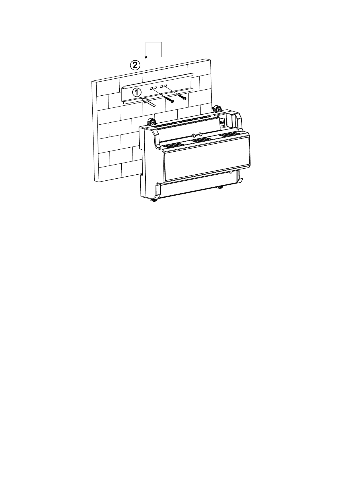
The device must be installed on solid and flat surface in order to guarantee
safety under load and earthquake. Otherwise, it may cause device to fall off or
turnover.
Do not drop or splash liquids onto the device, and do not place container with full
liquid on the device to prevent liquid spilling from entering the device.
Do not block air vent of the device or ventilation around the device. Otherwise,
temperature in device will rise and may cause fire.
Use the device only within rated input and output range.
Do not disassemble the device without professional instruction.
Please transport, use and store the product under appropriate temperature and
humidity.
Warning:
Please use battery properly to avoid fire, explosion and other dangers.
Please replace used battery with battery of the same type.
Do not use power line other than the one specified. Please use it properly within
rated range. Otherwise, it may cause fire or electric shock.
Please use power supply matching SELV requirements, and IEC60950-1 Limited
Power Source. Power supply shall follow requirements on device label.
For I-type structure product, connect it to power supply plug with GND
protection.
If you use power plug or appliance coupler as disconnecting device, please
maintain the disconnecting device available to be operated all the time.
Special Announcement
This manual is for reference only, subjected to the actual product.
All the designs, software and instructions here are subject to change without
prior written notice.
All damaged and losses caused by operation not following instructions in this
manual, are borne by the user.
All trademarks and registered trademarks are the properties of their respective

owners.
If there is any uncertainty or controversy, please refer to the final explanation of
us.
Please visit our website for more information.

1
1 Overview
The two-door one-way access controller is a controlling device which compensates video
monitoring and bidirectional talk. It has neat and modern design with strong functionality,
suitable for commercial building, corporation property and intelligent community.
It has:
It adopts slideway and lock installation design for easy installation and repair.
It integrates alarm, access control, video monitoring, fire alarm and control module
input.
It supports 2 sets of card readers (may set 2 as bidirectional card readers).
It supports 8 groups of input signal (unlock button *2, door sensor *2, vandal-proof
alarm *2, intrusion alarm *2).
It supports 4 groups of output control (electric lock *2, alarm output *2).
RS485 port, may extend to connect to lift control module, alarm or household control
module. It may connect upper device via RS485.
FLASH storage capacity is 16M (may extend to 32M), max supports 100,000 card
holders and 150,000 records.
It supports illegal intrusion alarm, unlock overtime alarm, forced card alarm and
forced setup. It also supports black-white list and patrol card setup
It supports setup of card period, password and validity. Guest card in additional has
setup of times of use.
It supports 128 groups of schedules, 128 groups of periods and 128 groups of holiday
schedule.
Data storage during outage, built-in RTC (support DST), online upgrading.

5
Figure 3- 3
Uninstallation method:
Step 1. Face screwdriver toward the slot and press it to fasten.
Step 2. Do it again for second slot, and you can take the device down.

6
4 Port
Device ports are illustrated in Figure 4- 1.
Figure 4- 1
Ports are defined as:
No.
Port
No.
Port
1
RS485 communication
8
Alarm output
2
Unlock+Door sensor
(door 1)
9
Dial-up switch
3
Unlock+Door sensor
(door 2)
10
TCP/IP, software platform port
4
Alarm input
11
Card reader (door 1)
5
Lock power output
12
Card reader (door 2)
6
Lock control output
(door 1)
13
Reset
7
Lock control output
(door 2
14
DC 12V power port
Indicators are defined as:

7
No.
Note
15
Lock status indicator
16
17
Power indicator
4.2 Cabling
Cabling ports of No.1 to 7 are shown as Figure 4- 2.
Figure 4- 2
Cabling ports of “RS485 communication” are as follows:
Port
No.
Cabling Port
485
Communication
1
485-
2
485+
3
GND
Cabling ports of “Unlock+Door sensor” are as follows:
Port
No.
Cabling Port
Note
Unlock+Door
Sensor
4
PUSH1
Unlock button (door 1)
5
SR1
Door sensor (door 1)
6
PUSH2
Unlock button (door 2)
7
SR2
Door sensor input (door 2)
8
GND
Unlock button and door
sensor
Cabling ports of “Alarm Input” are as follows:
Port
No.
Cabling Port
Note
Alarm
Input
9
ALM1
Smoke sensor alarm, sound/light
alarm and etc.
10
ALM2
Smoke sensor alarm, sound/light

8
Port
No.
Cabling Port
Note
alarm and etc.
Cabling ports of “Lock Control Output” are as follows:
Port
No.
Cabling Port
Note
Lock Control
Output
11
12V
Lock power supply
12
GND
13
NO1
Door lock off when outage
(door 1)
14
COM1
Lock power 12V input (door
1)
15
NC1
Door unlock on when outage
(door 1)
16
NO2
Door lock on when outage
(door 2)
17
COM2
Lock power 12V input (door
2)
18
NC2
Door unlock on when outage
(door 2)
Cabling ports of “Alarm Output” are as follows:
Port
No.
Cabling Port
Note
Output
Control
19
OUT1+
No. 1 alarm output
20
OUT1-
21
OUT2+
No. 2 alarm output
22
OUT2-
Cabing ports of card reader are shown in Figure 4- 3.
Figure 4- 3
“Door 1 Card Reader”corresponds to ports in the following chart. “Door 2 Card Reader”is
similar to “Door 1 Card Reader”.

10
5 Technical Specification
Parameter
Specification
Processor
32 bit ARM processor
Storage Capacity
16M
Max User
100,000
Max Record
150,000
Card Reader
Communication Port
Wiegand, RS485
Platform
Communication Port
TCP/IP
Input Card Reader
Quantity
2 groups
Working Power
Rated power 10-15VDC, rated current 0.75A
Schedule
128
Period
128
Holiday
128
Unlock Mode
Card, card+password, password, card or password,
card+fingerprint, fingerprint+password, fingerprint or
card or password, by period.
Cross-segment
Network
Support
Real-time Monitoring
Support
AlarmActivation
Support
Vandal-proofAlarm
Support
Illegal Intrusion Alarm
Support
Unlock Overtime
Alarm
Support
Forced Card and
Password Setup
Support
DST and Time Sync
Support
Online Upgrading
Support

11
Note:
This manual is for reference only. Slight difference may be found in user
interface.
All the designs and software here are subject to change without prior written
notice.
All trademarks and registered trademarks are the properties of their respective
owners.
If there is any uncertainty or controversy, please refer to the final explanation of
us.
Please visit our website or contact your local service engineer for more
information.
Table of contents
Other Dahua Technology IP Access Controllers manuals