manuals.online logo
Brands
  1. Home
  2. •
  3. Brands
  4. •
  5. Roger
  6. •
  7. IP Access Controllers
  8. •
  9. Roger MCX402-BRD User manual

Roger MCX402-BRD User manual

MCX402-1-KIT Installation Manual 2020-10-08
1/2
Roger Access Control System
MCX402-1-KIT Installation Manual
Expander firmware version: 1.0.4.259 or newer
Product version: 2.0
Document version: Rev. D
This document contains minimum information that is necessary for initial setup
and installation of the kit. The detailed description of configuration parameters
and functionalities of all components is specified in respective Operating
manuals available at www.roger.pl.
INTRODUCTION
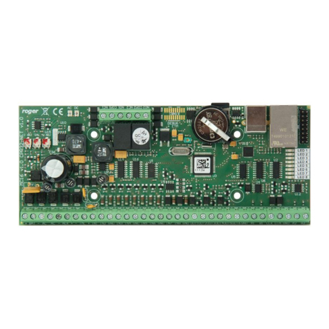
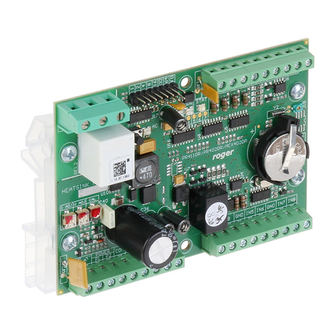
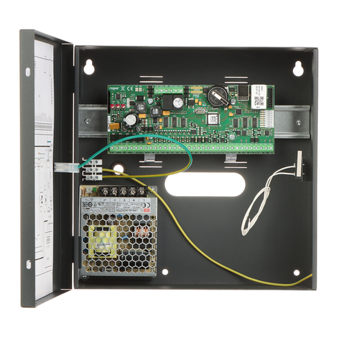
MCX402-1-KIT is the access expander kit for single read-in/read-out door in
RACS 5 system with Wiegand interface readers or PRT (RACS CLK/DTA)
readers depending on firmware of the expander. The kit includes MCX402-BRD
expander and ME14-24V metal box with 24VDC/50W power supply unit. The box
is adapted to installation of 7Ah battery for emergency supply. All elements of
controlled door including readers and door lock can be supplied from the kit.
Before connecting to controller, the expander should be assigned with
unoccupied address in range of 100-115. Addressing of the expander can be
done from computer by means of RogerVDM program or manually. Configuration
of the expander with RogerVDM requires RUD-1 interface.
CONFIGURATION WITH ROGERVDM PROGRAM
Fig. 1 Connection of MCX expander to RUD-1 interface for configuration
Expander programming procedure with RogerVDM software:
1. Connect the device to RUD-1 interface (fig. 1) and connect the RUD-1 to
computer’s USB port.
2. Start RogerVDM program, select MCX v1.xT device, firmware version,
RS485 communication channel and serial port with RUD-1 interface.
3. Click Connect, the program will establish connection and will automatically
display Configuration tab.
4. Enter unoccupied RS485 address in range of 100-115, enable Wiegand or
PRT terminals, configure input types (e.g. NC for IN6 according to fig. 4) and
other settings according to requirements of specific installation.
5. Click Send to Device to update the configuration of device.
6. Optionally make a backup by clicking Send to File… and saving settings to
file on disk.
7. Disconnect the expander from RUD-1 interface.
MANUAL ADDRESSING
The RS485 address of expander configured with RogerVDM is a software
address. Alternatively hardware RS485 address can be configured with jumpers
and such address has higher priority than software address.
Fig. 2 Manual addressing of expander
Note: Each time the hardware RS485 address is modified the device must be
restarted
MEMORY RESET
Memory reset procedure restores factory default settings including ID=100
software address.
Expander memory reset procedure:
1. Remove all connections from A, B, CLK and DTA terminals.
2. Put jumper on “64” contact and restart device with RST button on device
board or by switching supply off and on.
3. Remove jumper from “64” contacts when LED STAT (red), LED OPN and
LED SYS are ON.
4. LED OPN and LED SYS will switch off and device shall restart automatically
with factory default settings.
FIRMWARE UPDATE
Factory new expander is equipped with a firmware dedicated to Wiegand
readers. If the expander is to be operated with PRT readers then another
firmware must be uploaded. Such firmware is available at www.roger.pl.
Firmware update requires RogerISP program.
Expander firmware update procedure:
1. Connect the device to RUD-1 interface (fig. 1) and connect the RUD-1 to
computer’s USB port.
2. Put jumper on FDM contacts
3. Restart device with RST button on device board or by switching supply off
and on.
4. Start RogerISP software.
5. Select serial port emulated by RUD-1 interface and the option USB-RS485
Converter.
6. Select firmware file (*.hex), click Program and follow instructions on screen.
7. Once the firmware is uploaded remove the FDM jumper and restart the
device.
8. Start Memory reset procedure.
POWER SUPPLY
The kit is supplied from 24VDC/50W power supply unit. The metal box offers
space for installation of typical 7Ah backup battery which is connected to BAT+
and BAT- terminals of MCX402-BRD expander.
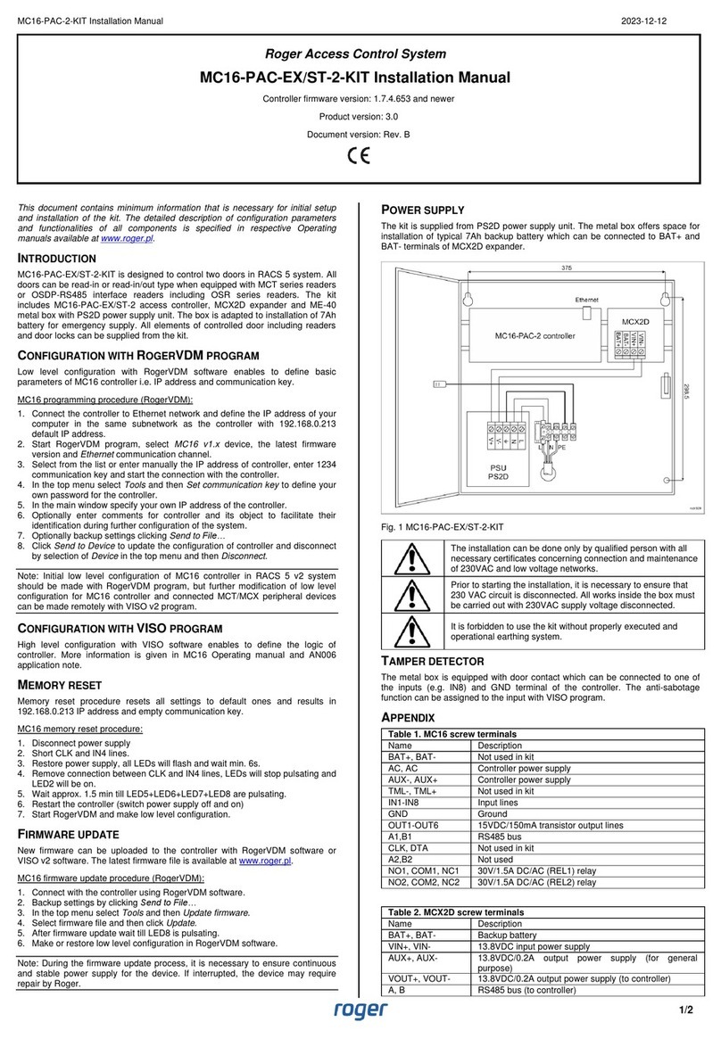
Fig. 3 MCX402-1-KIT
The installation can be done only by qualified person with all
necessary certificates concerning connection and maintenance
of 230VAC and low voltage networks.
Prior to starting the installation it is necessary to ensure that
230 VAC circuit is disconnected. All works inside the box must
be carried out with 230VAC supply voltage disconnected.
MCX402-1-KIT Installation Manual 2020-10-08
2/2
It is forbidden to use the kit without properly executed and
operational earthing system.

TAMPER DETECTOR
The metal box is equipped with door contact which can be connected to one of
the inputs (e.g. IN8) and GND terminal of the expander. The anti-sabotage
function can be assigned to the input within high level configuration of the
system.
APPENDIX
Table 1. MCX402-BRD screw terminals
Name
Description
BAT+, BAT-
Backup battery
P1
24VDC input power supply
P2
Ground
AUX
12VDC/1.0 output power supply (for door lock)
TML
12VDC/0.2A output power supply (for readers)
IN1-IN8
Input lines
GND
Ground
IO1, IO2
15VDC/1A transistor output lines
A, B
RS485 bus
CLK, DTA
RACS CLK/DTA bus
NO1, COM1, NC1
30V/1.5A DC/AC (REL1) relay
NO2, COM2, NC2
230V/1.5A AC (REL2) relay
Table 2. Specification
Supply voltage
230VAC, 50/60Hz (-15%÷+10%)
Power supply
LRS-50-24 24VDC/50W
Short circuit and overload
protection
Yes
Metal box
DC01 0.8mm metal sheet, grey anthracite colour
(RAL7016)
Tamper protection
NO/NC detector, 50VDC/50mA
Distances
Up to 150 m between kit and readers
IP Code
IP20
Environmental class
(acc. to EN 50133-1)
Class I, indoor general conditions, temperature:
+5°C to +40°C, relative humidity: 10 to 95% (no
condensation)
Dimensions H x W x D
255 x 255 x 90 mm
Weight
1,7 kg
Certificates
CE
Fig. 4 Typical door control with Wiegand readers
Fig. 5 Typical door control with PRT readers
Notes:
In case of read-in door, single reader is connected to the expander.
Any unoccupied IN1-IN8 inputs of the expander can be used for connection of
door contact and exit button.
In case of electrically incompatible Wiegand readers it might be necessary to
install PR-GP-BRD modules.
LED indicators of Wiegand readers can be controlled with IO1 and IO2
transistor outputs.
Diagrams include doors with electric strikes. In case of electromagnetic lock,
the NC terminal of relay is used instead of NO terminal.
Diagrams include exit buttons. In case of read-in/out doors they can be used
for emergency door opening.
This symbol placed on a product or packaging indicates that the
product should not be disposed of with other wastes as this may
have a negative impact on the environment and health. The user is
obliged to deliver equipment to the designated collection points of
electric and electronic waste. For detailed information on recycling,
contact your local authorities, waste disposal company or point of
purchase. Separate collection and recycling of this type of waste
contributes to the protection of the natural resources and is safe to
health and the environment. Weight of the equipment is specified in
the document.
Contact:
Roger Sp. z o. o. sp. k.
82-400 Sztum
Gościszewo 59
Tel.: +48 55 272 0132
Fax: +48 55 272 0133
Tech. support: +48 55 267 0126
E-mail: [email protected]l
Web: www.roger.pl

Other manuals for MCX402-BRD

2

This manual suits for next models

1

Other Roger IP Access Controllers manuals

Roger PRT12MF-DES User manual

Roger

Roger PRT12MF-DES User manual

Roger RFT1000 User manual

Roger

Roger RFT1000 User manual

Roger ME-14-24V User manual

Roger

Roger ME-14-24V User manual

Roger OSR88M-IO User manual

Roger

Roger OSR88M-IO User manual

Roger MCT84-BK-QB User manual

Roger

Roger MCT84-BK-QB User manual

Roger PR302 User manual

Roger

Roger PR302 User manual

Roger PR611-VP User manual

Roger

Roger PR611-VP User manual

Roger MCX402-BRD User manual

Roger

Roger MCX402-BRD User manual

Roger PR411DR-SET User manual

Roger

Roger PR411DR-SET User manual

Roger MCX102-BRD User manual

Roger

Roger MCX102-BRD User manual

Roger EDGE1 Series Product manual

Roger

Roger EDGE1 Series Product manual

Roger PR411DR User manual

Roger

Roger PR411DR User manual

Roger MC16-PAC-3-KIT User manual

Roger

Roger MC16-PAC-3-KIT User manual

Roger PR402DR User manual

Roger

Roger PR402DR User manual

Roger RKD32 User manual

Roger

Roger RKD32 User manual

Roger PR622 User manual

Roger

Roger PR622 User manual

Roger PR602LCD-DT-I User manual

Roger

Roger PR602LCD-DT-I User manual

Roger PR201 Assembly instructions

Roger

Roger PR201 Assembly instructions

Roger PR402 User guide

Roger

Roger PR402 User guide

Roger MCT88M-IO User manual

Roger

Roger MCT88M-IO User manual

Roger PR402DR User manual

Roger

Roger PR402DR User manual

Roger MCT12E User manual

Roger

Roger MCT12E User manual

Roger MCT80M-BLE User manual

Roger

Roger MCT80M-BLE User manual

Roger RFT1000 User manual

Roger

Roger RFT1000 User manual

Popular IP Access Controllers manuals by other brands

Cansec SmartLock UltraLite Plus installation manual

Cansec

Cansec SmartLock UltraLite Plus installation manual

ZKTeco C3 quick start guide

ZKTeco

ZKTeco C3 quick start guide

digicon dTower product manual

digicon

digicon dTower product manual

PACH & COMPANY Quantum QR5 Series Programming manual

PACH & COMPANY

PACH & COMPANY Quantum QR5 Series Programming manual

ZKTeco ProFace X installation guide

ZKTeco

ZKTeco ProFace X installation guide

Bticino IP DES manual

Bticino

Bticino IP DES manual

IOMO FG-1000 user manual

IOMO

IOMO FG-1000 user manual

ACT ACTENTRY A5 Operating and installation instructions

ACT

ACT ACTENTRY A5 Operating and installation instructions

Nitgen eNBioAccess-T2 user guide

Nitgen

Nitgen eNBioAccess-T2 user guide

TECOM ChallengerPlus Installation and Quick Programming Manual

TECOM

TECOM ChallengerPlus Installation and Quick Programming Manual

Cidron Standard Reader installation guide

Cidron

Cidron Standard Reader installation guide

EverFocus ERR-871 Specifications

EverFocus

EverFocus ERR-871 Specifications

IOMO FCA-2000 user manual

IOMO

IOMO FCA-2000 user manual

FingerTec TA700W installation guide

FingerTec

FingerTec TA700W installation guide

TDSi SOLOgarde user manual

TDSi

TDSi SOLOgarde user manual

Immotec iSafe Pro 360 Verso technical information

Immotec

Immotec iSafe Pro 360 Verso technical information

Citadele DIGIPASS 700 operating instructions

Citadele

Citadele DIGIPASS 700 operating instructions

ATN X-TRAC manual

ATN

ATN X-TRAC manual

manuals.online logo
manuals.online logoBrands
  • About & Mission
  • Contact us
  • Privacy Policy
  • Terms and Conditions

Copyright 2025 Manuals.Online. All Rights Reserved.