Daihen OTC RT3500S User manual

Welding Torch for Robot
Coaxial Power Cable for Robot
<Shock sensor built-in type>
RT3500S /H /L
RT5000S /H /L
RTW5000S /H /L
RZ3500S /H /L
Thoroughly read this
instruction manual to
operate the units correctly.
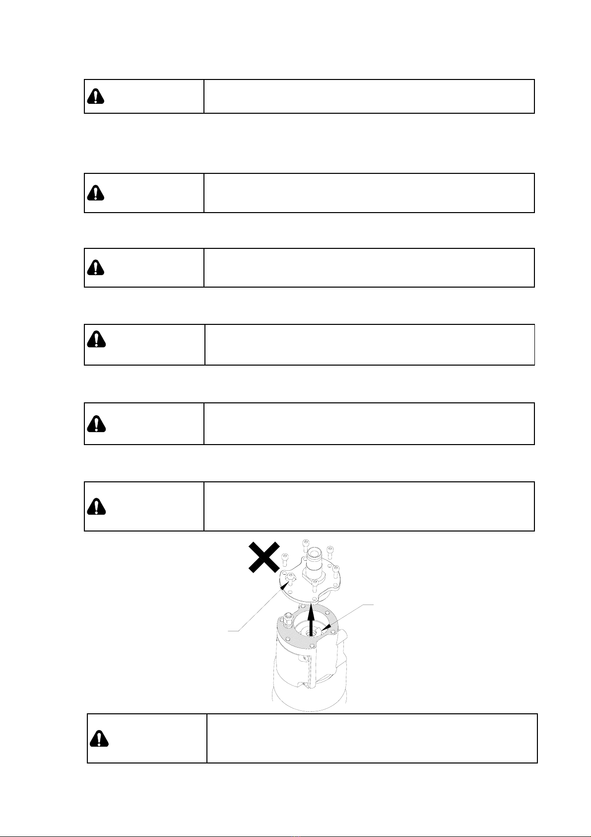
•Installation, maintenance, and repair of this
welding torch shall be made by qualified
persons or persons who fully understand
welding machines to secure the safety.
•To secure the safety, operation of this welding
torch shall be made by persons who have
knowledge and technical skill to fully
understand the contents of this manual and
handle the machine.
•Regarding safety education, utilize courses
and classes held by head/branch offices of
the Welding Society /Association and the
related societies/associations, and qualifying
examinations for welding experts/consultant
engineers.
•After thoroughly reading this manual, be sure
to retain it with the warranty in the place
where the persons concerned can read any
time. Read it again as occasion demands.
•If incomprehensible, contact our offices. For
servicing, contact our local distributor or sales
representatives in your country.
Our addresses and telephone numbers are
listed in the back cover of this Instruction
Manual.
Contents
①NOTES ON SAFETY .......................... S1
②IMPORTANT SAFEGUARDS ............. S2
③NOTES ON USE..................................... S7
1. Specifications ............................................1
2. Checking the Contents.............................6
3.
Installing and Adjusting Procedure of Welding Torch
......8
3.1 Mounting of Welding Torch on AII-V6 type
Manipulator.................................................................... 8
3.2 Mounting of Welding Torch on AII-B4 Type
Manipulator ............................................................... 14
3.3 Connecting the Water-cooled Torch
(RTW5000S/RTW5000H/RTW5000L).................. 19
3.4
Connecting the Hose to AII-B4
...................... 21
3.5 Handling Instructions for RT series Torch ............ 22
3.6 Handling Instructions for RZ series Torch ............ 23
4. Coaxial Power Cable for Robot ........... 25
4.1 Type of Coaxial Power Cables ............................... 25
4.2 When Using the DL Welding Power Supply......... 26
4.3 Connecting the Coaxial Power Cable ................... 28
4.4 Cutting the Liner........................................................ 29
4.5 Liner Crump Function .............................................. 30
5. Setting the Robot Controller................. 31
5.1 Checking the Tool Parameter ................................. 31
5.2 Checking the Shock Sensor Operation ................ 33
6. Troubleshooting ..................................... 34
7.
Replacement Parts for Various Wire Diameters .....
35
7.1 Replacement Parts for Various Wire Diameters
of Torch ........................................................................ 35
7.2 Replacement Parts for Various Wire Diameters
of Coaxial Power Cable ............................................ 38
8. Parts List ................................................. 39
Instruction Manual
= Safety and Operation = Instruction Manual No.
1L10603-E-2
For CO2/MAG


-S1-
1. Notes on Safety
●Before operating this product, thoroughly read this instruction manual first to operate the
product correctly.
●Cautions described in this instruction manual are to prevent you and other people from being
injured or damaged by having the product operated correctly and safely.
●Although this product is designed and manufactured in due consideration of safety, carefully
follow the notes and cautions described in this manual. Otherwise, there may occur an
accident causing serious injury or death.
●Various ranks of accidents resulting in injury, damage, or death may occur if mishandling the
product. The caution alert symbols and signals are classified into three ranks as below, used
throughout these instruction manual as well as warning labels put on each unit and device.
Symbol Signal Description
DANGER
Mishandling may cause seriously dangerous
situation that could result in serious injury or death to
personnel. Limited situation of great urgency.
WARNING Mishandling may cause a dangerous situation that
could cause serious injury or death to personnel.
CAUTION
Mishandling may cause a dangerous situation that
could cause medium or slight injury to personnel, or
material damage.
Hazards and special instructions described by CAUTION are very important as well.
Neglect of them may occasionally cause serious injury or death to personnel. Therefore, be sure to
follow the instructions described by all three safety alert symbols and signal words.
The meanings of "serious injury", "medium or slight injury", and "material damage" are as follows.
Serious injury :Injury with a sequela due to a loss of eyesight, injury, burn (high
temperature and low temperature), electric shock, a bone fracture,
poisoning and so on as well as injury that requires hospital
treatment or long treatment as an outpatient.
Medium or slight injury :Injury, burn, electric shock and so on that require no hospital
treatment nor long treatment as an outpatient.
Material damage :Damage to property, and direct and incidental / consequential
damage due to the damage to devices.
Ref.: IMPORTANT : The sign “IMPORTANT” indicates special instructions
necessary for the most efficient operation.
NOTES ON SAFETY

-S2-
2. Important Safeguard
2.1 Read, understand, and comply with all safety rules described at the beginning of
each instruction manual in addition to the following ones before starting Arc welding
operation.
WARNING Observe the following notices to prevent a serious accident
that results in serious injury or death.
1) This torch is designed and manufactured in due consideration of safety, but you must follow
the handling precautions described in this instruction manual. If you fail to do so, there may
occur an accident resulting in serious injury or death.
2) Related laws, regulations, and your company's standards should be observed in constructing
input power source, selecting an installation area, handling/storing/piping high pressure gas,
storing welded products, and disposing wastes.
3) Keep out of the robot operating zone and the welding area.
4) A person with pacemaker should not approach the operating welding machine and the welding
area unless his or her doctor permits. A welding machine generates a magnetic field around it
during powered, which will have a bad effect on the pacemaker.
5) Installation, maintenance, and repair of this torch should be performed by qualified personnel
or those who fully understand a welding torch for further safety.
6) Operation of this torch should be done by personnel who have knowledge and technical skill
to fully understand the contents of this manual and to handle the torch safely.
7) This torch must not be used for purposes other than welding.
2.2 Observe the following to prevent electric shock.
WARNING Do not touch live electrical parts.
Touching live electrical parts can cause fatal shock or severe
burns.
IMPORTANT SAFEGUARD
NV6 NB4

-S3-
1) Only qualified personnel should perform grounding work of the welding power supply and
workpiece, or a workpiece and powered peripheral jigs while abiding by domestic regulations.
2) Do not touch live electrical parts.
3) Always wear dry insulating gloves and other body protection. Do not wear torn or wet gloves/
work clothes.
4) Before doing the installation, inspection, maintenance, etc. of this product be sure to turn off
all the input power sources and check, several minutes later, that there is no charging voltage
since the condenser and the like may have been recharged.
5) Do not use cables with insufficient capacity, with damage, or with naked conductors.
6) Be sure to tighten the connections of cables and insulate them in order to prevent personnel
from touching those parts easily.
7) DO NOT use a welding machine with its case or cover removed.
8) Secure a firm foothold before initiating work. DO NOT perform work with an unstable
foothold or with a foothold at a height of two meters or above.
9) Make periodic inspection and maintenance. Damaged parts should be repaired before use.
10) Turn off POWER switch when not in use.
2.3 All the personnel in and around the working area including an operator should wear
appropriate protection to protect themselves from arc rays, spatters, slag, and noise
produced by welding.
●Install a lightproof wall where arc is generated.
WARNING
●Wear appropriate eye, ear, and body protection.
●Arc rays may cause inflammation of eyes and burns on skin
●Spatter s and slag may cause eye troubles and burns.
●Noise may cause hearing problems.
1) Wear lightproof glasses or a welder’s shield helmet with a proper shade of filter when welding
or watching a welder work.
2) INSTALL ARC PROTECTIVE CURTAINS in between an operator and arc rays.
3) WEAR PROPER SAFETY GLASSES in work area at all times.
4) WEAR PROPER EAR PROTECTION.
5) WEAR PROPER BODY PROTECTION including woolen clothing, flameproof apron and
gloves, leather leggings, high boots and leather arm and shoulder gauntlets.
6) WEAR PROPER SAFETY GLASSES to protect eyes and skin from spatters and slag.
IMPORTANT SAFEGUARD (continued)

-S4-
2.4 All the personnel in and around the working area including an operator should wear
appropriate protection to protect themselves from fumes and gases produced by
welding.
●DO NOT inhale fumes and gases generated by welding.
WARNING ●Ventilate the area sufficiently and wear a welder’s shield mask if
necessary.
●Fumes and gases generated by welding have a harmful effect on
human body.
●Welding in a small area may cause suffocation due to the lack of
air.
1) KEEP YOUR HEAD out of fumes and DO NOT inhale any.
2) USE FORCED EXHAUST VENTILATION at the arc.
3) VENTILATE the area to prevent build-up of fumes and gases.
4) If ventilation is insufficient, USE APPROVED BREATHING DEVICES.
5) READ AND FOLLOW WARNING LABELS on all containers of welding materials.
6) Before use, READ AND UNDERSTAND the manufacture's instructions, Material Safety Data
Sheets (MSDSs), and follow your employer's safety practices.
7) To prevent gas poisoning and suffocation, use a local ventilator or a respirator specified by
your country’s domestic laws.
8) Be sure to ventilate the area or wear a respirator by welding in a small place. A well-trained
watchman should observe the work.
9) Do not weld near the place where degreasing, cleaning or spraying is carried out. The heat
and rays of the arc can react with vapors to form highly toxic and irritating gases. If welding is
carried out there, harmful gases may be produced.
10) Toxic fumes and gases are produced when coated steel is welded. Be sure to ventilate the
area sufficiently or use a respirator.
IMPORTANT SAFEGUARD (continued)

-S5-
2.5 Prevent fire, explosion, burns and injury caused by heated workpiece, spatters, slag,
and arc sparks right after welding as described below.
●Do not weld near flammable materials.
●Watch for fire: keep a fire extinguisher nearby.
●NEVER do welding on inflammables such as a piece of wood or
cloth.
WARNING
●Do not weld on closed containers.
●Heated workpiece, spatters, slag and arc sparks right after welding
may cause fire.
●Incomplete cable connections, incomplete contacts in the current
circuit of the workpiece such as steel frames may cause a fire due to
the heat generated when powered.
●Arc generated on containers of inflammables such as gasoline may
cause an explosion.
●Welding of airtight tanks and pipes may cause a bursting.
●Touching a heated workpiece, spatters, slag or arc sparks will
cause a serious burn.
1) KEEP FLAMMBLE MATERIALES out of the robotic cell.
2) Welders should wear appropriate protection such as flameproof leather gloves, work clothes
with long sleeves, a leg cover, a flameproof leather apron in order to prevent burns caused by
touching heated workpiece, spatters, slag and arc sparks right after welding.
3) WATCH for fire.
4) Have a fire extinguisher nearby Operators should know how to use it.
5) DO NOT touch heated workpiece and peripheral jigs with inflammables such as a piece of wood
or cloth. Doing so might cause not only a fire but also burns.
6) DO NOT put heated workpiece close to inflammables right after welding..
7) Remove inflammables from the place where welding is carried out so that spatters and slag will
not strike them.
8) Do not use inflammable gases near the welding sight.
9) Tighten and insulate the cable connections completely.
10) Connect the cables on the workpiece side as close to the welding area as possible to prevent
the welding current from traveling along unknown paths and causing electric shock and fire
hazards.
11) A gas pipe with gas sealed in, an airtight tank and a pipe must not be welded, because they
might explode.
12) NEVER do welding on inflammables such as a piece of wood or cloth.
13) When welding a large-size structure such as a ceiling, floor, wall, etc., remove any inflammables
hidden behind a workpiece.
IMPORTANT SAFEGUARD (continued)

-S6-
For reference
PRINCIPAL SAFETY STANDARDS
Safety in Welding and Cutting, ANSI Standard Z49.1, from American
Welding Society.
Safety and Health Standards, OSHA 29 CFR 1910, from Superintendent of
Documents, U.S. Government Printing Office.
Recommended Practices for Plasma Arc Cutting, American Welding Society
Standard AWS C5.2, from American Welding Society.
Recommended Safe Practices for the Preparation for Welding and Cutting
of Containers That Have Held Hazardous Substances, American Welding
Society Standard AWS F4.1, from American Welding Society.
National Electrical Code, NFPA Standard 70, from National Fire Protection
Association.
Safe Handling of Compressed Gases in Cylinders, CGA Pamphlet P-1, from
Compressed Gas Association.
Code for Safety in Welding and Cutting, CSA Standard W117.2, from
Canadian Standards Association, Standards Sales.
Safe Practices For Occupation And Educational Eye And Face Protection,
ANSI Standard Z87.1, from American National Standards Institute.
Cutting And Welding Processes, NFPA Standard 51B, from National Fire
Protection Association.
IMPORTANT SAFEGUARD (continued)

-S7-
3. Notes on Use
3.1 Duty cycle
CAUTION ●Use the torch with the specified rated duty cycle or under
Otherwise, the welding torch may be deteriorated or burned out.
● The rated duty cycle of 50% indicates that the
torch shall be used at the rated welding current
for 5 minutes and then suspended for 5 minutes
out of 10 minutes.
● The rated duty cycle of 70% indicates that the
torch shall be used at the rated welding current
for 7 minutes and then suspended for 3 minutes
out of 10 minutes.
● Use of the welding torch with the excess rated
duty cycle may lead to the temperature rise
exceeding the allowable value, resulting in
damage or burn.
● When using RTW5000S, RTW5000H and
RTW5000L, are sure that coolant is being
supplied with the water tank. Otherwise, the
temperature of welding torch may rise to over
the allowable value, leading to damage or burn.
3.2 Inching
●Do not look into the tip hole in inching to cheek.
WARNING ●In inching, the welding torch tip must not be put near to your
face, eye, and body.
●Do not look into the tip hole in inching to check if the wire is fed.
The wire may spring out and stick into your face, eyes, and
body. It is very dangerous.
●In inching, the welding torch tip must not be put near to your face,
eyes, and body. The wire may spring out and stick into your face,
eyes, and body to injure.
Set the welding torch straight, feed the wire with pressing the INCH button, and then release the
button when the wire is protruded by 10mm from the tip of torch.
NOTES ON USE
Welding torch Rated duty cycle
RT3500S
RT3500H
RT3500L
350A 80%(CO2)
350A 60%(MAG)
RT5000S
RT5000H
RT5000L
500A 50%(CO2)
350A 70%(MAG)
RTW5000S
RTW5000H
RTW5000L
500A 70%(CO2)
400A 60%(MAG)
RZ3500S
RZ3500H
RZ3500L
350A 80%(CO2)
350A 60%(MAG)

-S8-
3.3 Replacement of Parts
CAUTION ●To prevent burns, comply with the following cautions.
●Do not directly touch the high-temperature parts of a nozzle, an electrode and so on.
●When welding, wear suitable protection such as leather gloves for welding.
●Do not replace torch tip elements before they cool off.
CAUTION ●If any parts are damaged, replace them with new ones for further
safety and better quality.
●Be sure to place an order for replacement parts at our sales office or our agency.
CAUTION ●Do not disassemble the shock sensor. If disassembled, gas
leak and malfunction may be caused.
3.4 Coolant
CAUTION ●Be sure to run the coolant for the torch of liquid-cooled specification.
Insufficient amount of running water may lead to damage of torch.
3.5 Cable hose
CAUTION
●Never let cable hoses neither touch any heated part of the
welded, put something heavy on top nor bend them excessively
because the welding torch might become damaged.
3.6 Shock sensor
CAUTION
●In the main body of shock sensor inside, a powerful coil spring is
had built-in.
Because there is a threat that a coil spring protrudes, please do
not dismantle a shock sensor.
CAUTION
●The shock sensor absorbs damage at the speed of the manual
operation (or equal with the manual operation).
The shock sensor is damaged at the speed faster than manual
operation.
SPRING
コイルバネ
CAUTION!
DO NOT DISASSEMBLE
分解禁止

-1-
Thank you for purchasing DAIHEN CO2/MAG welding torch.
Before use, read this instruction manual thoroughly to use the product correctly.
[Note] 1. The contents in this instruction manual are subject to change without prior notice.
2. We have carefully written the standard specifications to eliminate as many errors as possible.
Even if any errors are found in the contents, we are not responsible for any damage resulting
from those errors.
3. No part of this instruction manual may be reproduced or stored in any form without the express
written permission.
1. Specifications
This is the “CO2/MAG welding torch” to be used for CO2/MAG welding.
The specifications are shown in Table 1.1. (Refer to Fig.1.1 - 1.4 for the outline drawing.)
Table 1.1 Specifications of welding torch
Model
RT3500S
RT3500H
RT3500L
RT5000S
RT5000H
RT5000L
RTW5000S
RTW5000H
RTW5000L
Torch type Straight Curved
(45°)
Curved
(31°) Straight Curved
(45°)
Curved
(31°) Straight Curved
(45°)
Curved
(31°)
Welding
process CO2(MAG)
Max. operating
current 350A(350A) 500A(350A) 500A(400A)
Rated duty
cycle 80% (60%) 50% (70%) 70% (60%)
Wire type Solid wire, Flux cored wire
Applicable wire
(φ
0.8
)(φ
0.9
)(φ
1.0
)φ
1.2
(φ
1.4
)(φ
1.6
)
(
φ
1.2) (
φ
1.4
)
φ
1.6
Cooling system Air cooling Liquid cooling
Shock sensor SSV SSV、SSB SSV SSV、SSB SSV SSV、SSB
Note) 1. While using RTW5000S, RTW5000H and RTW5000L, are sure that DAIHEN coolant liquid is being
supplied with the water tank (PU-301).
2. The maximum operating current and rated duty cycle are different between CO2and MAG welding system.
3. Shock sensor function
Arc welding robots may cause the welding torch to come into contact with workpiece or jig, thus resulting in the
deformation of the welding torch or damage to the robot itself. To prevent such problem, this welding torch
incorporates the shock sensor function that outputs an external force detection signal the instant when the nozzle
portion gets displaced to immediately stop the robot if external force larger than that specified is applied to the torch
tip portion (nozzle portion). This function is incorporated on the assumption that the welding torch comes into
contact with workpiece or jig during robot teaching. Contact of the welding torch with it while in automatic operation
may cause damage to the robot or the torch.
The shock sensor function does not provide any guarantees against the accuracy of aiming point of the torch tip
portion. After the shock sensor gets activated, ensure the aiming point. (For detail, refer to information in Section
5.2.)
4. None of RZ3500S or RZ3500L or RZ3500H accepts stainless wire.
Model
RZ3500S RZ3500H RZ 350 0L
Torch type Straight Curved
(45°)
Curved
(31°)
Welding process CO2(MAG)
Max. operating
current 350A(350A)
Rated duty cycle 80% (60%)
Wire type
Solid wire, Flux cored wire
Applicable wire
(φ
0.9
)(φ
1.0
)
φ
1.2
(φ
1.4
)(φ
1.6
)
Cooling system Air cooling
Shock sensor SSV SSV、SSB

-2-
400
69.5330.5
140
45°
149.1
(156.6)
15
R100
65
4.2
Weight 2.3[kg] 5.06[lb]
Air-cooled 350A CO2/MAG curved torch
RT3500H with shock sensor “SSV”
140
4.5
310
45°
(156.6)
15
R100
128.6
65
4.2
Weight 1.9[kg] 4.18[lb]
Air-cooled 350A CO2/MAG curved torch
RT3500H with shock sensor “SSB”
14°
188
400
38.7
330.5
31°
144.7
(156.7)
15
R100
45°
65
4.2
Weight 2.4[kg] 5.28[lb]
Air-cooled 350A CO2/MAG curved torch
RT3500L with shock sensor “SSV”
95
4.5
310
124.2
31°
(156.7)
R100
65
4.2
15
Weight 1.9[kg] 4.18[lb]
Air-cooled 350A CO2/MAG curved torch
RT3500L with shock sensor “SSB”
140
385
69.5315.5
15 65
4.2
Weight 2.1[kg] 4.62[lb]
Air-cooled 350A CO2/MAG straight torch
RT3500S with shock sensor “SSV”
Note)
1. The shock sensor and the welding torch are
distinct products.
Select the appropriate shock sensor for the robot
type in use.
2. The weight shown in each drawing of air-cooled
350A torch with shock sensor “SSV” includes the
weight of the torch mounting bracket ASSY.
Fig. 1.1 Outline drawing of air-cooled 350A torch Unit (mm)

-3-
140
400
69.5
149.1
330.5
45°
(156.6)
20
R100
77
4
Weight 2.3[kg] 5.06[lb]
Air-cooled 500A CO2/MAG curved torch
RT5000H with shock sensor “SSV”
45°
(156.6)
20
140
4.5
310
R100
128.6
77
4
Weight 2.0[kg] 4.40[lb]
Air-cooled 500A CO2/MAG curved torch
RT5000H with shock sensor “SSB”
400
188
14°
31°
R100
77
4
20
(156.7)
144.7
330.5
45°
38.7
Weight 2.4[kg] 5.28[lb]
Air-cooled 500A CO2/MAG curved torch
RT5000L with shock sensor “SSV”
4.5
31°
124.2
310
R100
77
(156.7)
4
20
Weight 1.9[kg] 4.18[lb]
Air-cooled 500A CO2/MAG curved torch
RT5000L with shock sensor “SSB”
140
385
69.5315.5
20 774
Weight 2.2[kg] 4.84[lb]
Air-cooled 500A CO2/MAG straight torch
RT5000S with shock sensor “SSV”
Note)
1. The shock sensor and the welding torch are
distinct products.
Select the appropriate shock sensor for the robot
type in use.
2. The weight shown in each drawing of air-cooled
500A torch with shock sensor “SSV” includes the
weight of the torch mounting bracket ASSY.
Fig. 1.2 Outline drawing of air-cooled 500A torch Unit (mm)

-4-
140
59.5340.5
400
45°
159.1
(156.6)
20
R100
90
1
Weight 2.4[kg] 5.28[lb]
Liquid-cooled 500A CO2/MAG curved torch
RTW5000H with shock sensor “SSV”
45°
(156.6)
320
140
4.5
20
R100
90
1
138.6
Weight 2.1[kg] 4.62[lb]
Liquid-cooled 500A CO2/MAG curved torch
RTW5000H with shock sensor “SSB”
14°
192.8
350.5
164.7
(156.7)
90
R100
400
19.3
1
20
45°
Weight 2.6[kg] 5.72[lb]
Liquid-cooled 500A CO2/MAG curved torch
RTW5000L with shock sensor “SSV”
4.5
330
31°
144.2
(156.7)
90
20
1
Weight 2.0[kg] 4.40[lb]
Liquid-cooled 500A CO2/MAG curved torch
RTW5000L with shock sensor “SSB”
385
140
59.5325.5
90
20
1
Weight 2.3[kg] 5.06[lb]
Liquid-cooled 500A CO2/MAG straight torch
RTW5000S with shock sensor “SSV”
Note)
1. The shock sensor and the welding torch are
distinct products.
Select the appropriate shock sensor for the robot
type in use.
2. The weigh shown in each drawing of liquid-cooled
500A torch with shock sensor “SSV” includes the
weight of the torch mounting bracket ASSY.
Fig. 1.3 Outline drawing of Liquid-cooled 500A torch Unit (mm)

-5-
400
145
64.5
149.1
335.5
45°
(163.6)
R100
15
78
4
Weight 2.3[kg] 5.06[lb]
Air-cooled 350A CO2/MAG true constant contact
curved torch RZ3500H with shock sensor “SSV”
45°
(163.6)
15
4.5
145
315
R100
128.6
78
4
Weight 2.0[kg] 4.40[lb]
Air-cooled 350A CO2/MAG true constant contact
curved torch RZ3500H with shock sensor “SSB
400
156.3
31°
R100
(166.4)
350.5
45°
14°
197.7
20.5
15
4
78
Weight 2.5[kg] 5.50[lb]
Air-cooled 350A CO2/MAG true constant contact
curved torch RZ3500L with shock sensor “SSV”
330
31°
135.8
78
(166.4)
15
4
100
4.5
Weight 2.0[kg] 4.40[lb]
Air-cooled 350A CO2/MAG true constant contact
curved torch RZ3500L with shock sensor “SSB”
Weight 2.2[kg] 4.84[lb]
Air-cooled 350A CO2/MAG true constant contact
straight torch RZ3500S with shock sensor “SSV”
Note)
1. The shock sensor and the welding torch are
distinct products.
Select the appropriate shock sensor for the robot
type in use.
2. The weight shown in each drawing of Air-cooled
350A true constant contact torch with shock sensor
“SSV” included the weight of the torch mounting
bracket ASSY.
Fig. 1.4 Outline drawing of Air-cooled 350A true constant contact torch Unit (mm)
478
385
140
64.2
320.8
15

-6-
2. Checking the Contents
SSV SSB
Shock sensor unit
Mounting bolt(M5×15)・・・・・・・・・・・・・・・・・・・ 4 pieces
Spring washer(M5)・・・・・・・・・・・・・・・・・・・・・・ 4 pieces
Washer(M5)・・・・・・・・・・・・・・・・・・・・・・・・・・・・・ 4 pieces
Shock sensor unit
Hood
Power cable cover
Mounting bolt(M5×20)・・・・・・・・・・・・・・・・・・・ 4 pieces
Spacer・・・・・・・・・・・・・・・・・・・・・・・・・・・・・・・・・・ 4 pieces
Insulating bushing・・・・・・・・・・・・・・・・・・・・・・・ 4 pieces
Insulating dowel pin・・・・・・・・・・・・・・・・・・・・・ 2 pieces
Cable tie・・・・・・・・・・・・・・・・・・・・・・・・・・・・・・・・ 2 pieces
Fig. 2.1 Checking the contents of package
Note) 1. Use the mounting bolts (M5×40) listed above to mount the shock sensor unit on the mounting bracket.
2. Use the cable tie listed above to mount the power cable cover on the coaxial power cable.

-7-
RT3500S RT3500H RT3500L
Welding torch main body
RT5000S RT5000H RT5000L
Welding torch main body
RTW5000S RTW5000H RTW5000L
V6用 B4用
Welding torch main body
Wrench ・・・・・・・・・・・・・・・・・・・・ 1 piece
Applicator ・・・・・・・ ・・・・・・・・・・・ 1 piece
Cooling water hose(6m)・・・・・ 2 pieces
Elbow(For B4)・・・・・・・・・・・・・・ 2 pieces
Elbow(For V6)・・・・・・・・・・・・・・ 2 pieces
V6用 B4用
Welding torch main body
Wrench・・・・・・・・・・・・・・・・・・・・・・1 piece
Applicator・・・・・・・・ ・・・・・・・・・・・1 piece
Cooling water hose(6m)・・・・・ 2 pieces
Elbow(For B4)・・・・・・・・・・・・・・・2 pieces
Elbow(For V6)・・・・・・・・・・・・・・・2 pieces
V6用 B4用
Welding torch main body
Wrench・・・・・・・・・・・・・・・・・・・・・ 1 piece
Applicator ・・・・・・・ ・・・・・・・・・・・ 1 piece
Cooling water hose(6m)・・・・・ 2 pieces
Elbow(For B4)・・・・・・・・・・・・・・ 2 pieces
Elbow(For V6)・・・・・・・・・・・・・・ 2 pieces
RZ3500S RZ3500H RZ3500L
Welding torch main body
Fig. 2.2 Checking the contents of package
Note) 1. Use of the RTW5000S, RTW5000H, or RTW5000L Liquid-cooled torch requires a water tank in addition to this
torch. Purchase the water tank (PU-301) separately.
2. Use the wrench that comes with the Liquid-cooled torch to dismount the contact tip.

-8-
3. Installing and Adjusting Procedure of Welding Torch
3.1 Mounting of Welding Torch on AII-V6 Type Manipulator
3.1.1 Mounting of shock sensor and mounting bracket
(Note: Purchase the torch mounting bracket ASSY separately.)
Fig. 3.1 Mounting of torch and shock sensor (for 45°curved / straight torch)
(1) Assemble the mount (L6300B01) onto the output flange of manipulator using 4 pieces of hexagon socket
head cap screws (M6×12).
(2) Mount the L-bracket (L10620B03) to the mount that has assembled in the procedure (1) with 2 pieces of
hexagon socket head cap screws (M8×25).
(3) Mount the insulating bracket (L10620B02) to the L-bracket that has mounted in the procedure (2) with 2
pieces of hexagon socket head cap screws (M8×20).
(4) Mount the shock sensor onto the insulating bracket with 4 pieces of hexagon socket head cap screws
(M5×15).
(5) Loosen the hexagon socket head cap screw (M5×20) of shock sensor to insert the torch. Fix it by
tightening the screw.
Hexagon socket head cap screw
(4-M6X12)
Output flange
L bracket
(L10620B03)
Hexagon socket head cap screw
(2-M8X20)
Hexagon socket head cap screw
(2-M8X25)
Insulat ng bracket
(L10620B02)
Torch mount ng bracket ASSY
(L10620B)
Mount
(L6300B01)
Hexagon socket head cap screw
(4-M5X15)
Hexagon socket head cap screw
(M5X20)
Shock sensor
(SSV)
T p gauge
(L317X)[RT3500]
(L317Z)[RT5000]
(L10319H)[RTW5000]
(L10669D)[RZ3500]
T ghten ng Torque:7.0N・m
T ghten ng Torque:8.0N・m
Weld ng torch

-9-
(Note: Purchase the torch mounting bracket ASSY separately.)
Fig. 3.2 Mounting of torch and shock sensor (for 31°curved torch)
(1) Assemble the mount (L6300B01) onto the output flange of manipulator using 4 pieces of hexagon socket
head cap screws (M6×12).
(2) Mount the L-bracket (L10620B01 or L10620D01) to the mount that has assembled in the procedure (1)
with 2 pieces of hexagon socket head cap screws (M8×25).
Choose an L bracket according to the type of the welding torch. (For detail, refer to Fig. 3.2)
(3) Mount the insulating bracket (L10620B02) to the L-bracket that has mounted in the procedure (2) with 2
pieces of hexagon socket head cap screws (M8×20).
(4) Mount the shock sensor onto the insulating bracket with 4 pieces of hexagon socket head cap screws
(M5×15).
(5) Loosen the hexagon socket head cap screw (M5×20) of shock sensor to insert the torch. Fix it by
tightening the screw.
RT3500L
RT5000L
RTW5000L
RZ3500L
Torch mounting bracket ASSY
(L10620C):[RT3500L/RT5000L]
(L10620D):[RTW5000L/RZ3500L]
Welding torch
Hexagon socket head cap screw
(2-M8X20)
Hexagon socket head cap screw
(4-M6X12)
Output flange
For 31° torch L bracket
( 10620C01):[RT3500 /RT5000 ]
( 10620D01):[RTW5000 /RZ3500 ]
Hexagon socket head cap screw
(2-M8X25)
Mount
(L6300B01)
Tip gauge
( 317X)[RT3500]
( 317Z)[RT5000]
( 10319H)[RTW5000]
( 10669D)[RZ3500]
Insulating bracket
(L10620B02)
Hexagon socket head cap screw
(M5X20)
Shock sensor
(SSV) Hexagon socket head cap screw
(4-M5X15)Tightening Torque7.0N・m
Tightening Torque:8.0N・m

-10-
3.1.2 Mounting the torch gauge
Fig. 3.3 Mounting the torch gauge (for straight torch)
Fig. 3.4 Mounting the torch gauge (for 45°curved torch) Fig. 3.5 Mounting the torch gauge (for 31°curved torch)
(Note: Purchase the torch gauge ASSY separately.)
(1) As for the RT series dismount the nozzle and the contact tip from the torch. As for the RZ series dismount the nozzle
and the tip holder from the torch.
(2) Mount
the tip gauge firmly to the torch. (The gauge is an attached component of the torch mount.)
(3) Mount
the torch gauge ASSY with 2 pieces of hexagon socket head cap screws (M5x30). (The screws are
attached components of the torch gauge Assy.)
(4) Make sure that the reference point of torch gauge matches with the tip gauge end. If not, make adjustments
for the reference point to align with it.
In addition, about each part to use at the time of torch installation to the V6 type manipulator, confirm it in
Table 3.1.
L317X
350A トーチ用
for 350A torch
L317Z
500A
空冷トーチ用
for 500A torch
L10319H
500A
水冷トーチ用
for 500A torch
L10669D
RZ トーチ用
for RZ torch
エクステンション
Extension
15mm
エクステンション
Extension
20mm
エクステンション
Extension
20mm
エクステンション
Extension
15mm
15
15
RT3500S
RT3500H
RT3500L
RT5000S
RT5000H
RT5000L
RTW5000S
RTW5000H
RTW5000L
RZ3500S
RZ3500H
RZ3500L
Torch gauge ASSY
(L6300E)
Hexagon socket
head cap screw
(2-M5X30)
Detail drawing
Reference point
Torch gauge ASSY
(L6300C)
Detail drawing
Reference point
Hexagon socket
head cap screw
(2-M5X30)
Hexagon socket
head cap screw
(2-M5X30)
Torch gauge ASSY
(L10620E)
Detail drawing
Reference point
This manual suits for next models
11
Table of contents
Other Daihen Welding Accessories manuals
Popular Welding Accessories manuals by other brands

Miller Electric
Miller Electric DS-2 owner's manual

3M
3M Speedglas 100 User instructions

Lincoln Electric
Lincoln Electric Magnum PRO 100SG Operator's manual

DIVERSITECH
DIVERSITECH MINI-VAC2-010N1 Operation & maintenance manual

Nippon Gases
Nippon Gases Mango CS-300 manual

Kemppi
Kemppi SuperSnake GTX04HD operating manual

Unitor
Unitor UWF-SC12RC owner's manual

Matco Tools
Matco Tools WH900V instruction manual

3M
3M Speedglas 100 Series User instructions

VITO
VITO SECURITY VIMSE instruction manual

Scheppach
Scheppach AWH380 Translation of original instruction manual

Lincoln Electric
Lincoln Electric Weldline Street Art quick guide