DAIICHI QT2-500 User manual

QT-216-057
INSTRUCTION MANUAL
(DETAILED VERSION)
MULTI-TRANSDUCER
QT2-500

QT-216-057
1
Contents
Introduction ・・・・・・・・・・・・・・・・・・・・・・・・・・・・・・・・・・・・・・・・・・・・・・・・・・・・・・・・・・・・・・・・・・・・・ 2
Safety precaution ・・・・・・・・・・・・・・・・・・・・・・・・・・・・・・・・・・・・・・・・・・・・・・・・・・・・・・・・・・・・・・・・ 2
Composition of type ・・・・・・・・・・・・・・・・・・・・・・・・・・・・・・・・・・・・・・・・・・・・・・・・・・・・・・・・・・・・・ 3
1 Features of product ・・・・・・・・・・・・・・・・・・・・・・・・・・・・・・・・・・・・・・・・・・・・・・・・・・・・・・・・・・・・ 4
2 Dimensions and part names ・・・・・・・・・・・・・・・・・・・・・・・・・・・・・・・・・・・・・・・・・・・・・・・・・・・・・・ 4
3 Bundled items ・・・・・・・・・・・・・・・・・・・・・・・・・・・・・・・・・・・・・・・・・・・・・・・・・・・・・・・・・・・・・・・・・・ 4
4 Installation instructions ・・・・・・・・・・・・・・・・・・・・・・・・・・・・・・・・・・・・・・・・・・・・・・・・・・・・・・ 4
5 Connection ・・・・・・・・・・・・・・・・・・・・・・・・・・・・・・・・・・・・・・・・・・・・・・・・・・・・・・・・・・・・・・・・・・・・・ 6
6 Operation・Screen ・・・・・・・・・・・・・・・・・・・・・・・・・・・・・・・・・・・・・・・・・・・・・・・・・・・・・・・・・・・・・・ 8
6.1 Basic operation ・・・・・・・・・・・・・・・・・・・・・・・・・・・・・・・・・・・・・・・・・・・・・・・・・・・・・・・・・・・・ 8
6.2 Screen structure ・・・・・・・・・・・・・・・・・・・・・・・・・・・・・・・・・・・・・・・・・・・・・・・・・・・・・・・・・・・ 8
7 Display mode ・・・・・・・・・・・・・・・・・・・・・・・・・・・・・・・・・・・・・・・・・・・・・・・・・・・・・・・・・・・・・・・・・・・ 8
7.1 Measurement display ・・・・・・・・・・・・・・・・・・・・・・・・・・・・・・・・・・・・・・・・・・・・・・・・・・・・・・・・ 8
7.2 Setting value display ・・・・・・・・・・・・・・・・・・・・・・・・・・・・・・・・・・・・・・・・・・・・・・・・・・・・・・ 10
8 Setting mode ・・・・・・・・・・・・・・・・・・・・・・・・・・・・・・・・・・・・・・・・・・・・・・・・・・・・・・・・・・・・・・・・・・・ 11
8.1 Setting flow ・・・・・・・・・・・・・・・・・・・・・・・・・・・・・・・・・・・・・・・・・・・・・・・・・・・・・・・・・・・・・・・ 11
8.2 Setting method ・・・・・・・・・・・・・・・・・・・・・・・・・・・・・・・・・・・・・・・・・・・・・・・・・・・・・・・・・・・・・ 11
8.3 Setting menu ・・・・・・・・・・・・・・・・・・・・・・・・・・・・・・・・・・・・・・・・・・・・・・・・・・・・・・・・・・・・・・・ 12
9 Test mode ・・・・・・・・・・・・・・・・・・・・・・・・・・・・・・・・・・・・・・・・・・・・・・・・・・・・・・・・・・・・・・・・・・・・・・022
9.1 Test flow ・・・・・・・・・・・・・・・・・・・・・・・・・・・・・・・・・・・・・・・・・・・・・・・・・・・・・・・・・・・・・・・・・・022
9.2 Test menu ・・・・・・・・・・・・・・・・・・・・・・・・・・・・・・・・・・・・・・・・・・・・・・・・・・・・・・・・・・・・・・・・・・022
10 Specifications ・・・・・・・・・・・・・・・・・・・・・・・・・・・・・・・・・・・・・・・・・・・・・・・・・・・・・・・・・・・・・・・・ 23
10.1 Rating ・・・・・・・・・・・・・・・・・・・・・・・・・・・・・・・・・・・・・・・・・・・・・・・・・・・・・・・・・・・・・・・・・・・・ 23
10.2 Measurement item, Class ・・・・・・・・・・・・・・・・・・・・・・・・・・・・・・・・・・・・・・・・・・・・・・・・・・・ 24
10.3 Detailed specification ・・・・・・・・・・・・・・・・・・・・・・・・・・・・・・・・・・・・・・・・・・・・・・・・・・・・ 25
10.4 Measuring range ・・・・・・・・・・・・・・・・・・・・・・・・・・・・・・・・・・・・・・・・・・・・・・・・・・・・・・・・・・・ 29
10.5 Input - output characteristic example ・・・・・・・・・・・・・・・・・・・・・・・・・・・・・・・・・・・・・ 31
11 Multi-transducer setting software(QT2-CS-01)・・・・・・・・・・・・・・・・・・・・・・・・・・・・・・・・・ 35
11.1 Outline ・・・・・・・・・・・・・・・・・・・・・・・・・・・・・・・・・・・・・・・・・・・・・・・・・・・・・・・・・・・・・・・・・・・ 35
11.2 Operating environment ・・・・・・・・・・・・・・・・・・・・・・・・・・・・・・・・・・・・・・・・・・・・・・・・・・・・・ 35
11.3 System configuration ・・・・・・・・・・・・・・・・・・・・・・・・・・・・・・・・・・・・・・・・・・・・・・・・・・・・・・ 35
12 Troubleshooting ・・・・・・・・・・・・・・・・・・・・・・・・・・・・・・・・・・・・・・・・・・・・・・・・・・・・・・・・・・・・・・・ 36

QT-216-057
2
Introduction
Thank you for purchase of DAIICHI product.
Please read this instruction manual carefully before use.
Keep this manual for future reference.
Please contact with us in case this manual is lost or damaged.
Safety Precaution
■ Environment conditions
Please be sure to use this product in a place that meets the following conditions. In places that do
not meet this condition, malfunctions and failures, and performance and product life may be reduced.
① Within the range of ambient temperature -10...55 ℃, humidity 5...90 % RH.
② Place free of corrosive gas. (Corrosive gas:SO2 / H2S, etc.)
③ Place free of dust, salt and oily smoke.
④ Location that is not affected by vibration and shock.
⑤ Location that is not affected by external noise.
⑥ Altitude 2000m or less.
If the input to this product is an inverter output such as cycle control, SCR phase angle control and
PWM control, measurement error may increase.
■ Outdoor use conditions.
① These products are not a dustproof, waterproof, and splash proof construction.
Please avoid the place with much dust. Please do not install in the place directly exposed to the
rain and water droplets. (IP code:IP30)
② Please do not install in the place directly exposed to the sun even through the glass.
Discoloration and degradation of a name plate, and deformation of the box by the surface temperature
rise may cause.
③ Product life may shorten when the daily average temperature exceeds 40 ℃.
■ Mounting and wiring
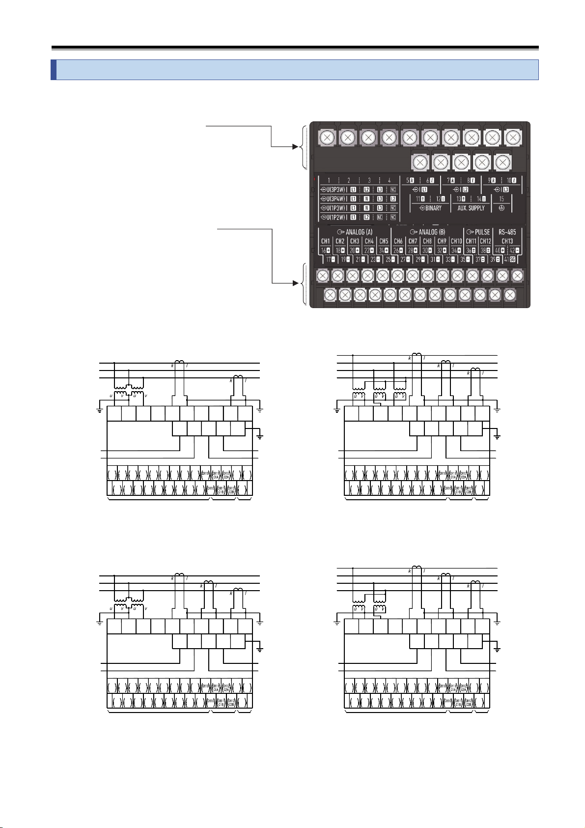
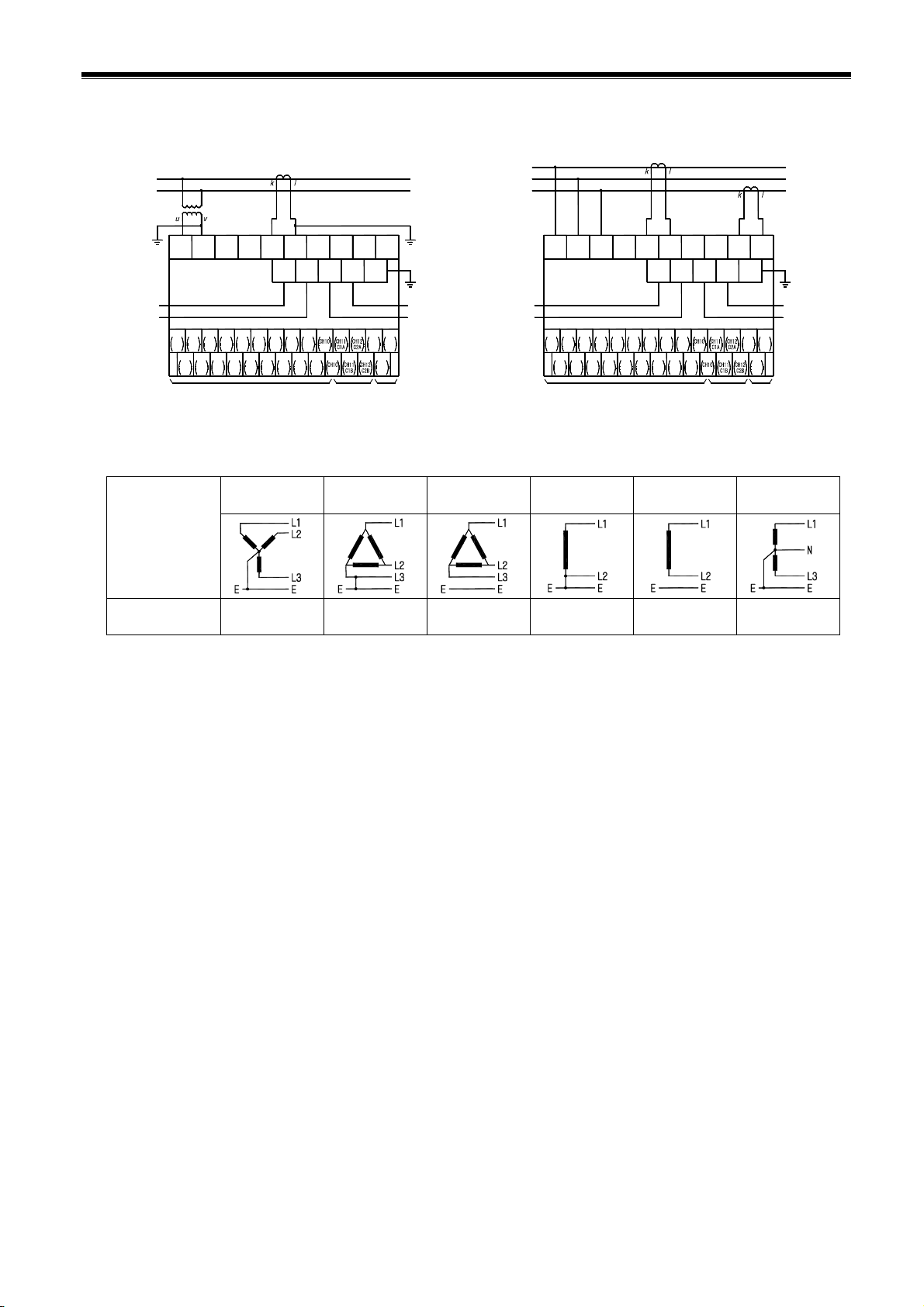
Please refer to this instruction manual for installation and the wiring.
Please refer to connection diagram for the wiring.
An improper connection may cause generation of high voltage on the CT secondary side, and
which may lead to device malfunction, burning or fire.
Hot line work is prohibited. There is a risk of explosion by electric shock, device
malfunction, burning, fire, or gas.
Please use an electrical wire size suitable with the rated current.
Use unsuitable size electric wire, which may lead to a fire.
Please check the tightening of the screw. If the screws are loose, it may cause a fire or
malfunction.
The terminal cover is installed for preventing an electric shock accident.
Please close terminal cover after wiring work.
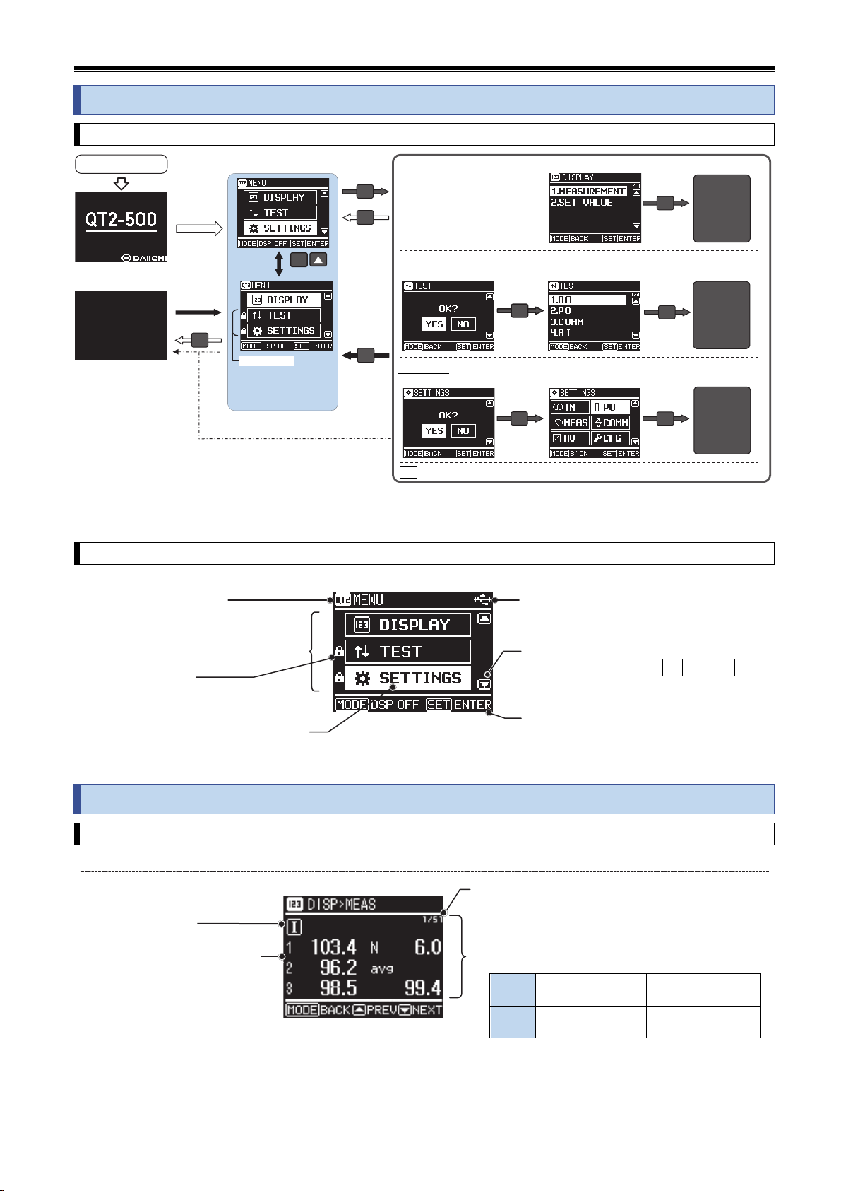
■ Preparation
This product must be set before use. Please read this manual and make the setting correctly.
If you make a mistake on the setting it does not operate correctly.
■ Maintenance and inspection
① Inspection during energization is dangerous.
② No replacement in periodic inspection.
③ Please wipe off lightly with the dry soft cloth.
④ Please do not use the organic solvent, chemicals, cleaners, etc., such as an alcohol, for cleaning.
■ Storage
When storing this product for a long period, please keep it in a place that satisfies the following
environmental conditions.
Within the range of ambient temperature (-20...70 ℃) and humidity (5...90 %RH).
Place where average daily temperature does not exceed 40 ℃.
Locations with little dust, corrosive gases, salt and oil smoke.
A place not subject to vibration or shock.

QT-216-057
3
■ Countermeasures against troubles
If this product breaks down within the warranty period, it will be repairs by DAIICHI Electronics.
■ Disposal
Please dispose of this product as industrial waste (noncombustible).
Mercury parts and a nickel-cadmium battery are not used for this product.
■ Warranty period
The warranty period of the product is one year after the date of delivery.
■ Warranty scope
In the state of the normal use of product-specification within the range according to this instruction manual,
the trouble within the warranty period performs exchange or repair gratuitously.
However, if it corresponds to the next, it does not warrant.
① If it breaks down when converted or repaired except our company.
② If it breaks down by use out of specification range.
③ If the cause of trouble is based on cause other than this product.
④ Transportation, movement, damage by falling, and trouble.
⑤ Other, natural disasters, disasters, etc. In the case where the supplier side (Company and agent) is
not responsible.
This warranty is a guarantee for the delivered product. Cannot warrant the damage induced by trouble of
this product.
■ Replacement cycle of the product
We recommend updating the product for 10 years as a rough standard.
■ Change of instruction manual written contents.
This instruction manual changes written contents without a notice by product improvement etc.
Composition of type
Type Specification code
QT2-500- ① Auxiliary supply ② Analog output
1 80...264 V AC, DC
AC/DC common use
1 0...5 V DC (600 Ω...∞) A 0...1 mA DC (0...10 kΩ)
2 0...10 V DC (2 kΩ...∞) B 4...20 mA DC (0...550 Ω)
2 20...57 V DC 3 1...5 V DC (600 Ω...∞) C -1...1 mA DC (0...10 kΩ)
4 -5...5 V DC (600 Ω...∞) Z Other (special specification)

QT-216-057
4
1. Features of product
Compliant with IEC60688:2012 (Transducer)、IEC62053:2003 (Static meters for active energy, Static meters
for reactive energy).
CE marking product
Possible to change by setting. (Wiring type, rated voltage, rated current)
Standard equipment. 10-analog output, 2-pulse output, RS-485 Communication output (MODBUS / Protocol A).
Connected to a PC with USB, you can write and read settings in dedicated software.
About the setting software, it is more downloadable than our web site.
URL;http://www.daiichi-ele.co.jp/en/
Using an organic electro-luminescence display of high contrast.
Configuration changes, measurement items can be displayed.
Wiring after installation can be confirmed in the test output by the front operation. To display the phase
angle between the voltage and current, and supports the determination of the wiring mistake points.
2. Dimensions and part names
3. Bundled items
① Instruction Manual (Instruction・Operation) ・・・・・・・・・・・・・・・ 1
② Attachment tool ・・・・・・・・・・・・・・・・・・・・・・・・・・・・・・・・・・・・・・・・・・ 4
③ Termination resister for communication (100Ω) ・・・・・・・・・・・ 1
4. Installation instructions
Please select indoors without low mechanical vibration, dust, and corrosive gas.
There is no limit of a mounting position.
Mounting instruction can select IEC 35 mm rail (DIN rail) mounting and screw mounting.
Please separate the mounting side-by-side interval by 10 mm or more as a measure against heat.
Please consider heat and separate more than 10 mm of the interval of mounting side by side.
Please consider heat and wiring space and separate more than 90 mm of the space above and below.
Please secure the space distance of a terminal and a metal panel 10 mm or more.
<Caution> Please do installation of a product and removal after a power supply and an input signal are
stopped.
M4 terminal cover
(access cover)
M3 terminal cover
(access cover)
Mounting leg ×4
IEC35mm rail (DIN rail)
Height:15mm
USB connector cover
Switch ×4
Cover open
Micro-USB
Power LED (White)
Organic Electro-luminescence display

QT-216-057
5
Mounting leg
QT2-500
QT2-500
QT2-500
QT2-500
10
10
10
5465
10
65
110 11090
10
10
5465 65
■ Mounting the IEC 35 mm rail (DIN rail)
Set product so that its slider is at the bottom. Position the upper hook at the rear side of product
on the DIN rail and push in the lower.
IEC, DIN rail (35mm width)
Slider 10 10 10
QT2-500 QT2-500
■ Remove from the IEC 35 mm rail (DIN rail).
Push down the slider utilizing a minus screwdriver and pull.
Slider
Screwdriver
■ Screw mounting
Attach the included mounting leg (×4).
Please install with M4 screw or M5 screw.
Tightening torque, M4:1.00...1.30 N・m
Tightening torque, M5:2.00...2.50 N・m
<Caution> Please mount a product from the bottom to prevent a fall.

QT-216-057
6
5. Connection
Open the terminal cover, please connections according to the wiring diagram below.
Terminal numbers and names are listed on the back of the terminal cover.
With terminal cover open
■ Upside terminal No.1...15
Auxiliary supply, Voltage, Current,
Binary input, Ground terminal
Screw:M4 screw
Conformity crimp-type terminal
:Crimp-type terminal for M4 screw.
Outside diameter for terminal:8.5 mm or less
Tightening torque:1.0...1.3 N・m
■ Downside terminal No.16...42
Analog output, Pulse output,
Communication output terminal
Screw:M3 screw
Conformity crimp-type terminal
:Crimp-type terminal for M3 screw.
Outside diameter for terminal:6 mm or less
Tightening torque:0.5...0.6 N・m
■ 3P3W [3-phase 3-wire] (2VT2CT) ■ 3P4W [3-phase 4-wire] (3VT3CT)
~
-
~
( )
+
( )
N
L2
L3
L1
28
CH7
+
ANALOG OUTPUT
( )
+
~
( )
-
~
EXT.RESET
INPUT
CH1...CH10
20
CH3
+
CH1
CH1
16
+
-
17 19
CH2
-
18
CH2
+
24
CH5
+
21
CH3
-
23
CH4
-
22
CH4
+
25
CH5
-
27
CH6
-
26
CH6
+
COMMUNICATION
OUTPUT
CH11,CH12
PULSE
OUTPUT
RS485
3632
CH9
+
29
CH7
-
31
CH8
-
30
CH8
+
33
CH9
-
35
-
34
+
3937
38
+
41
485
SG
RS
40
RS
485
42
-
RS
485
AUX.
SUPPLY
( )
-
( )
+
~
~
INPUT
EXT.RESET
(L1-k)
L2
L3
L1
U
1
(L1) (L2)
2
U V
(NC)(L3)
345
V
K
KL
(NC)
12
( )
( )
11
BI +
~BI
(L1-l)
6
(S1)
-
~
13
(NC)
7
(L3-k)
14
(S2)
89
15
(E)
10
(L3-l)
L
LOAD
OUTPUT
COMMUNICATION
ANALOG OUTPUT
+
CH7
28
CH1...CH10
CH3
-
21
CH1
-
17
+
CH1
16
CH2
-
19
+
CH2
18
+
CH3
20
+
CH5
24
CH4
-
23
+
CH4
22
-
CH5
25
CH6
-
27
+
CH6
26
OUTPUT
PULSE
CH11,CH12 RS485
36
+
CH9
32
CH7
-
29
CH8
-
31
+
CH8
30
CH9
-
33
-
35
+
34
+
485
RS
40
37 39
38
RS
485
SG
41
485
-
42
RS
SUPPLY
AUX.
( )
-
( )
~
~
+
BI
(L1-k)(L1)
1
(N)
2
UV
(L2)(L3)
345
VU VU
K
(L2-l)
8
~
-
( )
12
(L2-k)
( )
~
+
11
BI
(L1-l)
6
(S1)
13
7
(E)
(L3-k)
(S2)
14
9
15
(L3-l)
10
L
L
K
KL LOAD
■ 3P3W [3-phase 3-wire] (2VT3CT) ■ 3P4W [3-phase 4-wire] (2VT3CT)
ANALOG OUTPUT
+
CH7
28
+
CH3
20
CH1
CH1
+
16
+
-
17
CH2
-
19
CH2
18
CH1...CH10
+
CH5
24
+
CH3
-
21
CH4
-
23
CH4
22
+
CH5
-
25
-
CH6
27
CH6
26
COMMUNICATION
OUTPUT
OUTPUT
CH11,CH12
PULSE
36
+
CH9
32
+
CH7
-
29
CH8
-
31
CH8
30
+
CH9
-
33
-
35
34
SG
RS485
3937
38
+
485
41
RS
485
40
RS 485
RS
-
42
COMMUNICATION
OUTPUT
28
CH7
+
ANALOG OUTPUT
21
CH3
--
17
CH1
+
16
CH1 ++
19
CH2
-
18
CH2
20
CH3
CH1...CH10
24
CH5
++
23
CH4
-
22
CH4 +
25
CH5
-
27
CH6
-
26
CH6
36
CH11,CH12
PULSE
OUTPUT
32
CH9
++
29
CH7
-
31
CH8
-
30
CH8 +
33
CH9
-
35
-
34
SG
RS485
40
RS
485
+
37 39
38
41
RS
485
42
-
485
RS
L2
L3
N
( )
+
~
( )
-
~
L1
(L1-k)
( )
( )
~
~
-
+
L3
L2
L1
INPUT
EXT.RESET
1
(L1) (L2)
2
(NC)(L3)
345
UU V V
K
(L2-l)
~~
( )
12
( )
+
BI
11
BI
(L1-l)
6
(S1)
-
13
(L2-k)
7
(L3-k)
(S2)
14
89
(E)
15
(L3-l)
10
L
K
K L
L
SUPPLY
AUX.
-
( )
~
~
+
( )
EXT.RESET
INPUT
LOAD
(L1-k)
BI
(L1)
1
(N)
2
(NC)(L3)
345
UV VU
K
8
(L2-l)
~~
12
(L2-k)
( )
-
( )
11
+BI
(L1-l)
6
(S1)
13
7
(E)
(L3-k)
14
(S2)
9
15
10
(L3-l)
L
L
K
KL
AUX.
SUPPLY
( )
-
( )
+
~
~
LOAD

QT-216-057
7
■ 1P2W [1-phase 2-wire] ■ 1P3W [1-phase 3-wire]
N
L3
( )
+
~
( )
-
~
L1
ANALOG OUTPUT
CH1...CH10
COMMUNICATION
OUTPUT
CH11,CH12
PULSE
OUTPUT
RS485
28
CH7
+
(L1-k)
L2
( )
+
~
( )
-
~
EXT.RESET
INPUT
20
CH3
+
16 18
CH1
CH1
+
17 19
-CH2
-
CH2
+
22 24 26
CH5
+
21 23
CH3
-CH4
-
CH4
+
25 27
CH5
-CH6
-
CH6
+
12
(L1) (L2)
U V
345
(NC)(NC)
L1 K
3630 32 34
CH9
+
29 31
CH7
-CH8
-
CH8
+
33 35
CH9
- -
+
4038 42
3937 41
485
SG
RS
RS
485
+-
RS
485
(NC)
67
12
( )
11
( )
BI +
~BI
(L1-l)
13
(S1)
-
~
(NC)
8910
(NC)
14
(S2)
15
(E)
(NC)
AUX.
SUPPLY
+
( )
~
( )
-
~EXT.RESET
INPUT
L
LOAD
COMMUNICATION
OUTPUT
ANALOG OUTPUT
CH1...CH10
CH11,CH12
PULSE
OUTPUT
RS485
28
CH7
+
(L1-k)
BI
21
CH3
-
16 18 20
-
17
CH1
CH1
+
19
CH2
-
CH2
+CH3
+
22 24 26
CH5
+
23
CH4
-
CH4
+
25 27
CH5
-CH6
-
CH6
+
12
(L1) (N)
345
(NC)(L3)
3630 32 34
CH9
+
29 31
CH7
-CH8
-
CH8
+
33 35
CH9
- -
+
4038 42
RS
485
+
37 39 41
SG
RS
485
-
485
RS
8
(NC)
67
12
( )
-
~
11
( )
+
~BI
(L1-l)
13
(S1)
(NC)
910
(E)
(L3-k)
14
(S2)
15
(L3-l)
K L
KL
AUX.
SUPPLY
+
( )
~
( )
-
~
LOAD
・Maximum rated voltage
Wiring type
3P4W 3P3W
(Ground)
3P3W
(Ungrounded)
1P2W
(Ground)
1P2W
(Ungrounded) 1P3W
Maximum rated
voltage
277 V (L-N)
480 V (L-L) 220 V (L-L) 480 V (L-L) 220 V (L-L) 480 V (L-L) 220 V (L-N)
440 V (L-L)
・In the case of the low-pressure circuit (600 V or less), the secondary grounding of VT / CT is not required.
・Ground terminal (No.15), please be sure to ground. Ground is a class D grounding (grounding resistance
less than 100 Ω).
・Output wiring and the noise source (power line, steep voltage, the wire there is a current fluctuation),
please release as much as possible. Please use a twisted cable or twisted cable shielded.
・Minus (-) terminals are connected internally of analog output CH1...5. (Common, Non-isolated)
Minus (-) terminals are connected internally of analog output CH6...10. (Common, Non-isolated)
・Be used open the analog output terminal (current output), there is no damage to this product.
・Termination resistor for the communication output, please use at the end of equipment.
Please connect the termination resistor between the RS485 of (+)(-) terminals.
・By applying a voltage signal (auxiliary supply and the same rating) to the external reset input, maximum
demand value (current and power) can be reset.
・After the wiring work, please close the terminal cover.

QT-216-057
8
6. Operation and Screen
6.1 Basic operation
Note (1) By pressing and holding the switch for more than one second, it returns from each of the screen
to the MENU screen.
6.2 Screen structure
・Screen display Example:MENU
7.Display modes
7.1 Measurement display
(1) Display
■ Measurands
■ Phase / line display
■ Page No.
Current page / Total pages
■ Measurement value
Input is converted into the %.
Example:110 V, 5 A
I,HI 0...5 A 0...100.0 %
U,HU 0...150 V 0...100.0 %
P/Q/S -1 kW/kvar...
1 kW/kvar/kVA -100.0~100.0 %
Power factor, frequency, active energy,
harmonics distortion / content display a
real measured value.
Refer to section 10.4 for details.
POWER ON
Display OFF
DISPLAY
TEST
SETTINGS
Selection screen
Selection screen
Selection screen
Confirmation screen
Confirmation screen
YES
SET
YES
SET SET
SET
Setting
mode
(P11-)
Test
mode
(P22-)
MODE is pressed with each screen, return to the before screen. (Confirmation screen skips.)
MENU
MODE
Push 3 sec
MODE
Switch
operation
No operation (1 to 30 min.:Setting)
MODE
1 sec. (1)
SET
Display
mode
(P8-)
MODE
SET
TEST/SETTING locked.
During the lock cannot
be migrated to the test
mode and setting mode.
■ Main display
Display the item, settings,
measurement etc..
■ Operation guidance
Display the operation at the time
of switch operation.
■ USB icon
To display when the USB connection.
■ Display name
■ Cursor position (highlight)
■ Switch icon
Displayed when the
▲
and
▼
of the operation is required.
■ Lock icon
Displays at the time of
the test / setting lock.

QT-216-057
9
(2) Operation
①【MENU】→ 「DISPLAY」
SET
→「MEASUREMENT」
SET
→ Measurement display mode.
② Select the measurement element to be displayed. (
▲
▼
switch)
No.1 Current display No.2 Demand current display No.50 Harmonic 15th RMS value
(3) Measurement item
Page Measurement Screen
display
Wiring type
3P3W 3P4W 1P2W 1P3W
1 Current, Current (power flow) I 1,2,3,avg (2) 1,2,3,N,avg (2) I 1,3,N
2 Demand current Id 1,2,3,avg (2) 1,2,3,N,avg (2) Id 1,3,N
3 Maximum demand current Idmax 1,2,3,avg (2) 1,2,3,N,avg (2) Idmax 1,3,N
4 Line voltage, Phase voltage U 12,23,31,avg
(2)
12,23,31,LLavg,
1N,2N,3N,LNavg (3) U 13,1N,3N
5 Active power P Σ (2) 1,2,3,Σ (2) P Σ (2)
6 Demand power Pd Σ (2) 1,2,3,Σ (2) Pd Σ (2)
7 Maximum demand power Pdmax Σ (2) 1,2,3,Σ (2) Pdmax Σ (2)
8 Reactive power Q Σ (2) 1,2,3,Σ (2) Q Σ (2)
9 Apparent power S Σ (2) 1,2,3,Σ (2) S Σ (2)
10 Power factor PF Σ (2) 1,2,3,Σ (2) PF Σ (2)
11 Frequency f f f f f
12 Active energy Wh Incoming (+) / Outgoing (-)
13 Reactive energy (Incoming) +varh LAG/LEAD
14 Reactive energy (Outgoing) -varh LAG/LEAD
Page Measurement Measurands Wiring type
3P3W 3P4W 1P2W 1P3W
15
Harmonic
current
Distortion factor
HI
%
THD
2VT,2CT
1,3
2VT,3CT
1,2,3
1,2,3 HI 1,3
16 5th conversion content CONV.5th
17...23 3th,5th,7th,9th,11th,13th,
15th,content
3th,5th,7th,9th,
11th,13th,15th
24 5th conversion RMS value
RMS
CONV.5th
25 Fundamental-wave RMS value 1st
26...32 3th,5th,7th,9th,11th,13th,
15th,RMS value
3th,5th,7th,9th,
11th,13th,15th
33
Harmonic
voltage
Distortion factor
HU
%
THD
12,23
2VT,3CT
1N,3N
3VT,3CT
1N,2N,3N
HU 1N,3N
34 5th conversion content CONV.5th
35...41 3th,5th,7th,9th,11th,13th,
15th,content
3th,5th,7th,9th,
11th,13th,15th
42 5th conversion RMS value
RMS
CONV.5th
43 Fundamental-wave RMS value 1st
44...50 3th,5th,7th,9th,11th,13th,
15th,RMS value
3th,5th,7th,9th,
11th,13th,15th
Note (2) avg:Average, Σ:Total.
Note (3) Since the line voltage and phase voltage that is displayed on the 2 page, the following pages No. will
be +1. (3P4W)

QT-216-057
10
7.2 Setting value display
(1) Display
Example:Analog output settings
Page Setting item Display Setting contents
1 Input
Top Wiring type
Center VT ratio
Bottom CT ratio
2...11 Analog output
Top CH No.
Output factor
Bottom Input range for output
value
12
13 Pulse output
Top CH No.
Center Output factor
Bottom Output pulse rate
14 Communication
output
Top CH No.
Protocol
Center Address
Bottom Bit rate
(2) Operation
①【MENU】→ 「DISPLAY」
SET
→「SET VALUE」
SET
→ Measurement display mode.
② Select the setting value to be displayed. (
▲
▼
switch)
No.1 No.2...11 No.12,13 No.14
Input settings Analog output settings Pulse output settings Communication output settings
■ Page No.
Number of pages /
Total number of pages
■ Setting value
Display the set value
of the right table.

QT-216-057
11
8.Setting modes
8.1 Setting flow
8.2 Setting method
(1) Display
(2) Operation
① Each setting display → Setting change of ▲ ▼ → Push
SET
(When indicating
SET
+, SET is pushed
for more than 1 second.) → Enter
② When the setting is confirmed, to display the "レ" indicating the current setting in place of the
changed setting value.
③ When ▲ ▼ is pushed lengthily, the set value changes at high speed.
▪Setting item
▪Switch icon
▪Page No.
Current page
/
Total page
▪Setting value (✓)
Example:Wiring type setting Example:Current range setting
Operate the ▲▼.
▪Setting cursor ▪Setting value
▲ ▼ in the increase
or decrease.
Move by ▲▼
▪Operation guidance
Display the operation at the time of switch
operation
▪With the next hierarchies
SET
SET
YES
MODE
Wiring type
VT
CT
Phase voltage
full scale
Current range
Demand current
interval
Voltage range
Demand active
power range
Harmonic interval
Power flow
Power factor
Wh/varh unit per
count
Frequency range
Active power
range
Power factor range
Reactive power
Method / Range
Output pattern
Output element
Output specification
Output element
Output pulse rate
Protocol
Address
Bit rate
Output limiter
Display
Reset
Software version
Data bits
MENU Confirmation Setting
Select an item in the ▲ ▼
Select the NO. To return to the menu in the SET.
Input Measurement Analog output Pulse output Communication output Configuration
Setting management
No.
Parity
Output adjustment
Apparent power
range Stop bit
Power flow
reactive power
▲
▼
SET
MODE
SET
MODE
SET
MODE SET
MODE SET
MODE SET
MODE
▲ ▲
▲ ▲ ▲
▼ ▼ ▼
▼ ▼
SET
MODE

QT-216-057
12
Setting range
Primary current Secondary
current
5 A 60 A 750 A 5000 A 5 A
6 A 75 A 800 A 6000 A 1 A
7.5 A 80 A 900 A 7500 A -
8 A 100 A 1000 A 8000 A -
10 A 120 A 1200 A 9000 A -
12 A 150 A 1500 A 10 kA -
15 A 200 A 1600 A 12 kA -
20 A 250 A 1800 A 15 kA -
25 A 300 A 2000 A 20 kA -
30 A 400 A 2500 A 30 kA -
40 A 500 A 3000 A - -
50 A 600 A 4000 A -
8.3 Setting menu
(1) Input setting IN
Setting item Description Content
Wiring type
【WIRING TYPE】
Set wiring type of
input circuit.
3P3W sets up the
number of CT.
3P4W sets up the
number of CT, and the
number of VT.
【Wiring type】 【Number of CT】
<Cautions> If this setup is performed,
all set points will be initialized.
Please set up first.
VT
【VT】
Set in accordance
with the use VT.
Primary voltage
- PRIMARY,
Secondary voltage
- SECONDARY
【VT select】 【Primary voltage】
Default setting
3P3W:6600 V/110 V
3P4W:440 V/440 V (Direct)
1P2W:3300 V/110 V
1P3W:110 V/110 V (Direct)
<Cautions> In direct connection, please set a primary voltage and a secondary
voltage as the same value.
CT
【CT】
Set in accordance
with the use CT.
Primary current
- PRIMARY,
Secondary current
- SECONDARY
【Primary/Secondary】 【Primary current】
Default setting
3P3W:100 A/5A
3P4W:1500 A/5 A
1P2W:50 A/5 A
1P3W:500 A/5 A
Phase voltage
full-scale
【ULN SCALE】
Set phase voltage
values for the upper
limit of the analog
output rating. (3P4W
and 1P3W)
In case of 3P3W and
1P2W, there is no
setting item.
【3P4W】 【1P3W】
MODE
SET
MODE
SE T
MODE
SET
MODE
SET
Thick-frame:Default setting
Setting range
3-phase 3-wire 3P3W 2VT,2CT
2VT,3CT
3-phase 4-wire 3P4W 2VT,3CT
3VT,3CT
1-phase 2-Wire 1P2W
1-phase 3-wire 1P3W
Setting range
Primary voltage Secondary
voltage
110 V 6600 V 66 kV 110 V
220 V 11 kV 77 kV 220 V
440 V 13.2 kV 110 kV 440 V
880 V 13.8 kV 132 kV -
1100 V 16.5 kV 154 kV -
1650 V 18.4 kV 187 kV -
2200 V 22 kV 220 kV -
3300 V 33 kV - -
110 V rating
Setting range
3P4W 1P3W
150/√3 V 150 V
150 V 300 V
Thick-frame:Default setting
Example of setting
Wiring type Setting value Input / Output
3P4W 150/√3 V U1N,U2N,U3N 0...86.6
V
/
4...20 mA
1P3W 150 V U1N,U3N 0...150
V
/
4...20 mA

QT-216-057
13
(2) Measurement setting MEAS
Setting item Description Content
Current range
【I RANGE】
Set current
measurement values
for the upper limit
of the analog output
rating range.
Rated current
=100.00 %
Demand current
interval
【Id INTVL】
Set interval
of demand current
measurement.
Voltage range
【U RANGE】
Set voltage
measurement values
for the upper limit
of the analog output
rating range.
Rated voltage
=110.00 %
Active power
range
【P RANGE】
Set active power
measurement values
for the upper limit /
lower limit of the
analog output rating
range.
【Upper or Lower】 【Upper】
Rated power
=100.00 %
・The output element when the "+ΣP, +P1, +P2, +P3" is selected, the range
is the upper setting from zero. (Lower setting is invalid)
If the upper setting is less than 20 %, the output is the lower limit of the
rated output range (in case of 4...20 mA, 4 mA).
・If the upper setting range from the lower setting, please select the next
output element. "±ΣP, ±P1, ±P2, ±P3"
In addition, in the case where the upper setting to 0.00%, will be in the
range of lower setting from zero.
・Demand power and the maximum demand power, the range will be the only upper
setting from the lower setting.
Example of setting [Rating 1000 W (110 V, 5 A)]
<Cautions> It cannot change into the set point from which the difference of
upper set point and lower set point becomes less than 20 %.
Demand active
power interval
【Pd INTVL】
Set interval of
demand active power
measurement.
Please set up similarly with reference to a setup (above) of the demand
current interval.
MODE
SET
Thick-frame:Default setting
Setting range
30.00 ... 100.00 ...120.00 % 0.01 % step
Example of setting (CT ratio:100 A / 5 A)
Setting value Input / Output
80.00 % 0...80 A ( /4 A) / 4...20 mA
Thick-frame:Default setting
Setting range
0 s 20 s 50 s 3 min 6 min 9 min 20 min
5 s 30 s 1 min 4 min 7 min 10 min 25 min
10 s 40 s 2 min 5 min 8 min 15 min 30 min
Thick-frame:Default setting
Setting range
100.00 ... 150.00 ...180.00 % 0.01 % step
Example of setting (CT ratio:100 A / 5 A)
Setting value Input / Output
150.00 % 0...9000 V ( /150 V) / 4...20 mA
Thick-frame:Default setting
Setting range
Upper 0.00 ... 100.00 ...120.00 % 0.01 % step
Lower -120.00 ... 0.00 % 0.01 % step
No. Output
factor
Lower
settings
Upper
settings Input / output
1 +ΣP,±ΣP 0.00 % 83.33 % 0...833.3 W / 4...20 mA
2 ±ΣP -66.67 % 66.67 % 0...666.7 W / 1...5 V
3 ±ΣP -50.00 % 50.00 % -500...0...500 W / -5...0...5 V
4 ±ΣP -25.00 % 100.00 % -250...1000 W / 4...20 mA
5 ±ΣP -50.00 % 0.00 % 0...-500 W / 4...20 mA
6 +ΣP -50.00 % 0.00 % 4 mA (For the upper limit of
less than 20 % at +ΣP)

QT-216-057
14
Setting item Description Content
Reactive power
【Q】
Set operation method
of reactive power.
And, set reactive
power measurement
values for the upper
limit / lower limit
of the analog output
rating range.
【Operation method
/
Range】 【Arithmetic】
Rated reactive power
= 100.00 %
・In the case where the upper setting to 0.00 %, will be in the range of
lower setting (LEAD) from zero.
・If the analog output element is a reactive power (power flow), it will
be the lower setting = negative upper setting. (Lower setting is invalid)
If the upper setting is less than 20 %, the output is the lower limit of
the rated output range (in case of 4...20 mA, 4 mA).
In this case, the upper limit set value is set to 20 % or more.
<Cautions> It cannot change into the set point from which the difference of
upper set point and lower set point becomes less than 20 %.
During outgoing (P<0), polarity as viewed from the incoming side
(Reference V fixed)
MODE
SET
Thick-frame:Default setting
Setting range
Q=UIsinφ
Q=√S2-P2
Thick-frame:Default setting
Setting range (Positive:LAG,Negative:LEAD)
Upper 0.00 ... 100.00 ... 120.00 % 0.01 % step
Lower -120.00 ... -100.00 ... 0.00 % 0.01 % step
Example of setting [Rating 1000 var (110 V, 5 A)])
No. Lower
settings
Upper
settings Input / Output
1 -75.00 % 75.00 % LEAD 750...0...LAG 750 var / -5...0...5 V
2 -25.00 % 100.00 % LEAD 250...LAG 1000 var / 4...20 mA
3 0.00 % 83.33 % 0...LAG 833.3 var / 4...20 mA
4 -83.33 % 0.00 % 0...LEAD 833.3 var / 4...20 mA
LEAD LAG
LEAD LAG
270° 90°
0°
180°
Reference V
Incoming (Power purchase)
【LAG/LEAD polarity】
Current of
lagging phase
Current of
leading phase
Outgoing (Power selling)

QT-216-057
15
Setting item Description Content
Reactive power
(power flow)
【Qpf】
Set output method
of reactive power
(power flow).
Operates with the reactive power Q range upper limit setting. (Lower limit value
= negative upper setting)
Set the upper limit value to 20% or more. If set to less than 20%, the output
will be the lower limit of the rated output range.
・In the pattern of the two-quadrant (incoming only), is the output of the
equivalent 0var at the time of outgoing.
・In the pattern of the two-quadrant (outgoing only), is the output of the
equivalent 0var at the time of incoming.
During outgoing (P<0), polarity as viewed from the outgoing side
(Reference V, 180° inversion)
Apparent power
range
【S RANGE】
Set apparent power
measurement values
for the upper limit /
lower limit of the
analog output rating
range.
Please set up similarly with reference to a setup (P13) of current range.
Rated apparent power
= 100.00 %
Thick-frame:Default setting
Setting range
4 quadrant 4QUADRANT 2 quadrant
(Incoming) 2QUADRANT(+)
20mA
12mA
4mA Outgoing Incoming
1 1 1 0 LEAD LAG [kvar]
0 LEAD LAG
20mA
12mA
4mA
1 1 1 0 LEAD LAG [kvar]
0 LEAD LAG
Outgoing Incoming
2 quadrant 2QUADRANT 2 quadrant
(Outgoing) 2QUADRANT(-)
20mA
12mA
4mA
1 1 1 0 LEAD LAG [kvar]
0 LEAD LAG
20mA
12mA
4mA Outgoing Incoming
1 1 1 0 LEAD LAG [kvar]
0 LEAD LAG
20mA
12mA
4mA
1 1 1 0 LEAD LAG [kvar]
0 LEAD LAG
Outgoing Incoming
Thick-frame:Default setting
Setting range
30.00 ... 100.00 ... 120.00 % 0.01 % step
LEAD LAG
LAG LEAD
270° 90°
0°
180°
Reference V
(Incoming)
Incoming (Power purchase)
【LAG/LEAD polarity】
Current of
lagging phase
Current of
leading phase
Outgoing (Power selling)
Leading
current
Lagging
current
Reference V
(Outgoing)

QT-216-057
16
Setting item Description Content
Power factor
range
【PF RANGE】
Set power factor
measurement value to
the rated output
range of the analog
output.
During outgoing (P<0), polarity as viewed from the incoming side
(Reference V fixed)
Power factor
(power flow)
【PFpf】
Set output means of
current
power-factor.
Please set up
similarly with
reference to a setup
(P12) of reactive
power (power flow).
During outgoing (P<0), polarity as viewed from the power outgoing side
(Reference V, 180° inversion)
Frequency range
【f RANGE】
Set frequency
measurement value to
the rated output
range of the analog
output.
Thick-frame:Default setting
Setting range Output (Example)
LEAD 0.5...1...LAG 0.5 4...12...20 mA
LEAD 0 ...1...LAG 0.5 1... 3...5 V
LAG 0.5...1...LEAD 0.5 -1... 0...1 mA
LAG 0 ...1...LEAD 0 -5... 0...5 V
Thick-frame:Default setting
Setting range
4 quadrant 4QUADRANT
2 quadrant 2QUADRANT
2 quadrant (Incoming) 2QUADRANT(+)
2 quadrant (Outgoing) 2QUADRANT(-)
Thick-frame:Default setting
Setting range Output (Example)
45...55 Hz 4...20 mA
55...65 Hz 1...5 V
45...65 Hz -1...1 mA
LEAD LAG
LEAD LAG
270° 90°
0°
180°
Reference V
Incoming (Power purchase)
Current of
lagging phase
Current of
leading phase
Outgoing (Power selling)
LEAD LAG
LAG LEAD
270° 90°
0°
180°
Reference V
(Incoming)
Incoming (Power purchase)
Current of
lagging phase
Current of
leading phase
Outgoing (Power selling)
Leading
current
Lagging
current
Reference V
(Outgoing)

QT-216-057
17
Setting item Description Content
Wh/varh unit
per count
【Wh/varh】
Set unit per count
of Wh/varh display
(and communication
data).
・Integrating the set value as the least significant
digit, up to a maximum of 9 digits (999999999).
Integrate again from "0" if it exceeds 9 digits.
・Full load power (kW/kvar)
= K×VT primary voltage (V)×CT primary current (A)×10-3
K:3P3W,3P4W=√3, 1P2W=1, 1P3W=2
Note(4) The unit of a display and communication data is MWh/Mvarh.
Harmonic
interval
【H INTVL】
Set interval of
harmonic
measurement.
Thick-frame:Default setting
Setting range
0 min 5 min 30 min
1 min 10 min -
2 min 15 min -
(3) Analog output setting AO
Setting item Description Content
Output
pattern
【PATTERN】
The measurement
element outputted
to CH1...10 is set
up from the pattern
prepared
beforehand.
Case of elements set individually CH, it will be MANUAL.
Note(5) 3P4W,1P3W:I1,1P2W:I
Note(6) 3P4W,1P3W:U1N,1P2W:U
Note(7) 1P2W:+P,PF
Thick-frame:Default setting
Setting range Phase CH1 CH2 CH3 CH4 CH5
MANUAL All For each element setting
NORMAL
3P3W I1 I2 I3 U12 U23
3P4W I1 I2 I3 U1N U2N
1P2W I U +P Q PF
1P3W I1 I3 IN U1N U3N
DEMAND
3P3W Id1 Id2 Id3 ΣPd Idmax1
3P4W Id1 Id2 Id3 IdN ΣPd
1P2W Id Pd Idmax Pdmax OFF
1P3W Id1 Id3 IdN ΣPd Idmax1
ISOLATION 3P3W I1 (5) U12 (6) +ΣP (7) ΣPF (7) f
HARMONIC 3P3W I1 (5)
% 3rd % 5th % 7th % THD RMS 1st
Setting range Phase CH6 CH7 CH8 CH9 CH10
MANUAL All For each element setting
NORMAL
3P3W U31 +ΣP ΣQ ΣPF f
3P4W U3N +ΣP ΣQ ΣPF f
1P2W f OFF OFF OFF OFF
1P3W U13 +ΣP ΣQ ΣPF f
DEMAND
3P3W Idmax2 Idmax3 ΣPF OFF OFF
3P4W Idmax1 Idmax2 Idmax3 IdmaxN ΣPdmax
1P2W OFF OFF OFF OFF OFF
1P3W Idmax3 IdmaxN ΣPdmax OFF OFF
ISOLATION 3P3W I1 (5) U12 (6) +ΣP (7) ΣPF (7) f
HARMONIC 3P3W U12 (6)
% 3rd % 5th % 7th % THD RMS 1st
Thick-frame:Default setting
Full load power kW/kvar Output pulse rate, kWh(kvarh)/pulse
Below 1 0.01 0.001 0.0001 0.00001
Over 1 Below 10 0.1 0.01 0.001 0.0001
Over 10 Below 100 1 0.1 0.01 0.001
Over 100 Below 1,000 (4) 10 1 0.1 0.01
Over 1,000 Below 10,000 (4) 100 (4) 10 1 0.1
Over 10,000 Below 100,000 (4) 1,000 (4) 100 (4) 10 1
Over 100,000 Below 1,000,000 - (4) 1,000 (4) 100 (4)
10
Over 1,000,000 Below 10,000,000 - - (4) 1,000 (4)
100
Over 10,000,000 Below 100,000,000 - - - (4)
1,000

QT-216-057
18
Setting item Description Content
Output element
【ELEMENT】
Set measurement
element outputted
to CH1...CH10.
(CH individual)
【CH set】 【Element】
・1,2,3, N is phase. avg is the average of each phase. Σ represents the total.
・If it is set as OFF, an output will serve as a lower limit value of the
rated-output range. (In case of 4...20mA is 4mA.)
・In the case of one side of the active power range (0...+P[W]), please select
the +P. In the case of both side of the active power range (±P[W]), please
select the ±P.
See the power range setting for more information.
Output
specification
【SPEC】
Set rated-output
range at the time of
output
specification
(0...5 V, 1...5 V,
0...10 V).
(CH individual)
【CH set】 【0...5 V/1...5 V】 Thick-frame:Default setting
Setting range
0...5 V
spec.
1...5 V
spec.
0...10 V
spec.
0...5 V 0...5 V 0...10 V
1...5 V 1...5 V 2...10 V
In the case of other output specifications, a setting item is skipped.
MODE
SET
Measurement Measurands Wiring type
3P3W 3P4W 1P2W 1P3W
Current I 1,2,3,avg 1,2,3,N,avg I 1,3,N
Current (power flow) Ipf 1,2,3 1,2,3, Ipf 1,3
Demand current Id 1,2,3,avg 1,2,3,N,avg Id 1,3,N
Maximum demand current Idmax 1,2,3,avg 1,2,3,N,avg Idmax 1,3,N
Line voltage,
Phase voltage U 12,23,31,
avg
12,23,31,LLavg,
1N,2N,3N,LNavg U 13,1N,
3N
Active power P +Σ +1,+2,+3,+Σ +P +Σ
±Σ ±1,±2,±3,±Σ ±P ±Σ
Demand power Pd Σ 1,2,3,Σ Pd Σ
Maximum demand power Pdmax Σ 1,2,3,Σ Pdmax Σ
Reactive power Q Σ 1,2,3,Σ Q Σ
Reactive power (power flow) Qpf Σ 1,2,3,Σ Qpf Σ
Apparent power S Σ 1,2,3,Σ S Σ
Power factor PF Σ 1,2,3,Σ PF Σ
Power factor (power flow) PFpf Σ 1,2,3,Σ PFpf Σ
Frequency f f f f f
Measurement Measurands Wiring type
3P3W 3P4W 1P2W 1P3W
Harmonic
current
Distortion factor
HI
THD
2VT2CT
1,
3
2VT3CT
1,
2,
3
1,
2,
3 HI 1,
3
5th conversion
content %
CONV.5th
3rd,5,7,9,11,13,
15th,content
3rd,5,7,9,
11,13,15th
5th conversion RMS
value
RMS
CONV.5th
Fundamental-wave RMS
value 1st
3rd,5,7,9,11,13,
15th,RMS value
3rd,5,7,9,
11,13,15th
Harmonic
voltage
Distortion factor
HU
THD
12,
23
2VTCT
1N,
3N
3VT3CT
1N,
2N,
3N
HU 1N,3N
5th conversion
content %
CONV.5th
3rd,5,7,9,11,13,
15th,content
3rd,5,7,9,
11,13,15th
5th conversion RMS
value
RMS
CONV.5th
Fundamental-wave RMS
value 1st
3rd,5,7,9,11,13,
15th,RMS value
3rd,5,7,9,
11,13,15th
MODE
SET

QT-216-057
19
Setting item Description Content
Output limiter
【LIMIT】
Set ON/OFF of
output limiter.
(CH individual)
If a setup is ON, an output will be restricted with the following value.
Upper limit:+1 % and lower limit:-1 % for the output span.
【CH set】 【ON/OFF】
Thick-frame:Default setting
Setting range
OFF
ON
If the output specification is 4...20 mA,
Limiter OFF:Range of 0.80...23.20 mA
Limiter ON :Range of 3.84...20.16 mA
Output
adjustment
【ADJUST】
BIAS adjustment and
SPAN adjustment of
analog output are
performed according
to CH individual.
An output is fluctuated by ▲ ▼ and an adjustment value is decided by SET.
【CH set】 【BIAS/SPAN set】 【SPAN adjustment】
Please adjust to when connected equipment and matching is required.
(4) Pulse output setting PO
Setting item Description Content
Output element
【ELEMENT】
Set measuring
element to pulse
output to CH12. (CH
Individual)
【CH set】 【Element set】
Thick-frame:Default setting
Setting range
CH11 CH12
Pulse OFF OFF OFF
Active energy (Incoming) +Wh +Wh
Active energy (Outgoing) -Wh -Wh
Reactive energy (Incoming, LAG) +varh LAG +varh LAG
Reactive energy (Incoming, LEAD) +varh LEAD +varh LEAD
Reactive energy (Outgoing, LAG) -varh LAG -varh LAG
Reactive energy (Outgoing, LEAD) -varh LEAD -varh LEAD
Output pulse
rate
【RATE】
Set output pulse
rate of CH12. (CH
Individual)
【CH set】 【Pulse rate】
Thick-frame:Default setting
Full load power(kW, kvar) Output pulse rate, kWh(kvarh)/pulse
Below 1 0.1 0.01 0.001 0.0001
Over 1 Below 10 1 0.1 0.01 0.001
Over 10 Below 100 10 1 0.1 0.01
Over 100 Below 1,000 100 10 1 0.1
Over 1,000 Below 10,000 1,000 100 10 1
Over 10,000 Below 100,000 10,000 1,000 100 10
Over 100,000 Below 1,000,000 100,000 10,000 1,000 100
Over 1,000,000 Below 10,000,000 1,000,000 100,000 10,000 1,000
Over 10,000,000 Below 100,000,000 10,000,000 1,000,000 100,000 10,000
MODE
SET
MODE
SET
MODE
SET
MODE
SET
Thick-frame:Default setting
Adjustment range
BIAS SPAN
-10.00... 0.00 ...+10.00 % 90.00... 100.00 ...110.00 %
MODE
SET
Table of contents
Other DAIICHI Transducer manuals
Popular Transducer manuals by other brands

Balluff
Balluff BTL7-C/E508-M Series user guide

Panametrics
Panametrics T17 installation guide

S+S Regeltechnik
S+S Regeltechnik PREMASGARD 111 Series Operating Instructions, Mounting & Installation

Airmar
Airmar P48W Owner's guide and installation instructions

PCI
PCI FT-1003 Operation & maintenance manual

Fisher
Fisher 646 instruction manual

MKS
MKS Baratron 127A instruction manual

Measurement Computing
Measurement Computing KPSI 351 Series user manual

CARLO GAVAZZI
CARLO GAVAZZI SPT-90 operating instructions

Humminbird
Humminbird APEX Series installation guide

Aerospace Logic
Aerospace Logic FF200X Series Operation guide

Simrad
Simrad TRANSDUCER - INSTALLATION GENERIC REV H installation manual