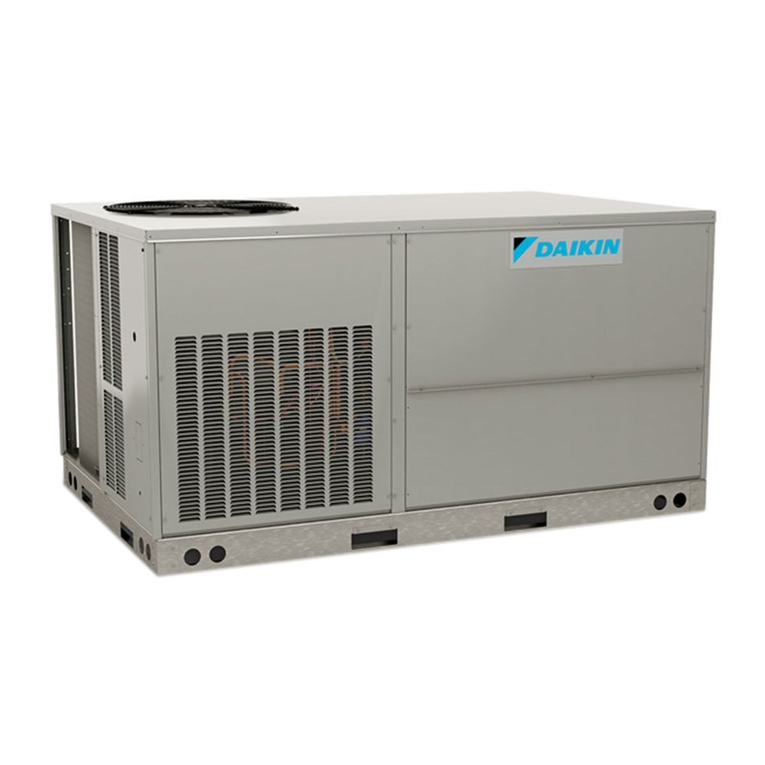
Daikin RE50KV1 User manual

REMOVAL
PROCEDURE
SERVICE MANUAL
5.0/6.0 kW Class
Outdoor Unit
Non-Inverter
Pair Type
Si011192

Service Manual
Removal Procedure
Outdoor Unit
Applicable Models
zCooling Only
RE50KV1
RE50KV14
RE50LV1V
RE50LV16
RE50LV169
RE60LV169
RE50MV16

Si011192
Removal Procedure 1
Table of Contents
1. Removal of Outer Panels ........................................................................2
2. Removal of Outdoor Fan / Fan Motor (Pattern 1) ...................................4
3. Removal of Outdoor Fan / Fan Motor (Pattern 2) ...................................6
4. Removal of Electrical Components (Pattern 1) .......................................8
5. Removal of Electrical Components (Pattern 2) .....................................15
6. Removal of Sound Blankets..................................................................23
7. Removal of Capillary Tube (Pattern 1)..................................................24
8. Removal of Capillary Tube (Pattern 2)..................................................25
9. Removal of Capillary Tube (Pattern 3)..................................................26
10.Removal of Compressor ASSY (Pattern 1)...........................................27
11.Removal of Compressor ASSY (Pattern 2)...........................................30
Note: The illustrations may be slightly different depending on the model.

Removal of Outer Panels Si011192
2Removal Procedure
1. Removal of Outer Panels
Procedure Warning Be sure to wait for 10 minutes or more after turning off all power
supplies before disassembling work.
Step Procedure Points
1Remove the 4 screws
and remove the top
panel.
Take care not to cut your
finger by the fins of the
outdoor heat exchanger.
2Remove the 7 screws
of the front panel.
Top panel
(R15386)
(R15384)
(R15387)
Front panel

Si011192 Removal of Outer Panels
Removal Procedure 3
3Lift the front panel and
unfasten the 3 hooks on
the left side and the 2
hooks on the right side.
4Remove the 4 screws
and remove the
discharge grille.
Step Procedure Points
(R16908)
Discharge grille
(R14277)

Removal of Outdoor Fan / Fan Motor (Pattern 1) Si011192
4Removal Procedure
2. Removal of Outdoor Fan / Fan Motor (Pattern 1)
Procedure Warning Be sure to wait for 10 minutes or more after turning off all power
supplies before disassembling work.
Step Procedure Points
1Pull out the 2 terminals
[A1] [B1] from the fan
capacitor (C12R).
Fan capacitor (C12R)
Magnetic contactor (K1M)
2Pull out the terminal [5]
from the magnetic
contactor (K1M).
3Release the fan motor
lead wire from the hook.
4Remove the screw of
the fan motor fixing
plate.
5Remove the fan motor
fixing plate.
Be careful so as not to
damage the top part of the
outdoor heat exchanger fins.
Put the fan motor lead wire
through the back of the fan
motor when reassembling so
as not to be entangled with
the outdoor fan.
(R16854)
Fan capacitor
Magnetic
contactor
Fan motor lead wire
to fan motor:
red
to fan motor: white
to magnetic
contactor: red
B1B2
A1A2
(R17464)
to fan motor: black
(R15160)
(R16855)
Fan motor
fixing plate
(R16856)
(R3249)
Lead wire Outdoor fan

Si011192 Removal of Outdoor Fan / Fan Motor (Pattern 1)
Removal Procedure 5
6
7
8
Remove the nut and
remove the outdoor fan.
Unfasten the 2 hooks.
Release the fan motor
lead wire.
Remove the 4 screws
and remove the fan
motor.
When reassembling, fit the
lower hooks into the bottom
frame.
Nut size: M6
Align the mark of the
outdoor fan with the D-cut
section of the motor shaft
when reassembling.
Screw size: M4 × 16
Step Procedure Points
(R15385)
(R15160)
Outdoor
fan
D-cut
(R15161)
Hook
Fan motor
(R15162)
10 mm
(R17447)

Removal of Outdoor Fan / Fan Motor (Pattern 2) Si011192
6Removal Procedure
3. Removal of Outdoor Fan / Fan Motor (Pattern 2)
Procedure Warning Be sure to wait for 10 minutes or more after turning off all power
supplies before disassembling work.
Step Procedure Points
1Pull out the 2 terminals
from the fan capacitor
(C2R).
Fan capacitor (C2R)
Magnetic contactor (K1M)
2Pull out the terminal [5]
from the magnetic
contactor (K1M).
3Release the fan motor
lead wire from the hook.
4Remove the screw of
the fan motor fixing
plate.
5Remove the fan motor
fixing plate.
Be careful so as not to
damage the top part of the
outdoor heat exchanger fins.
Put the fan motor lead wire
through the back of the fan
motor when reassembling so
as not to be entangled with
the outdoor fan.
(R16343)
Magnetic contactor
Fan motor lead wire
Fan capacitor to fan motor:
red
to fan motor:
white (R17640)
A2 14 6 4 2
A1 13 531
to fan motor:
black (R17641)
(R15158)
(R16182)
Fan motor
fixing plate
(R3249)
Lead wire Outdoor fan

Si011192 Removal of Outdoor Fan / Fan Motor (Pattern 2)
Removal Procedure 7
6
7
8
Remove the nut and
remove the outdoor fan.
Unfasten the 2 hooks.
Release the fan motor
lead wire.
Remove the 4 screws
and remove the fan
motor.
When reassembling, fit the
lower hooks into the bottom
frame.
Nut size: M6
Align the mark of the
outdoor fan with the D-cut
section of the motor shaft
when reassembling.
Screw size: M4 × 16
Step Procedure Points
(R15385)
(R15160)
Outdoor
fan
D-cut
(R15161)
Hook
Fan motor
(R15162)
10 mm
(R17447)

Removal of Electrical Components (Pattern 1) Si011192
8Removal Procedure
4. Removal of Electrical Components (Pattern 1)
Procedure Warning Be sure to wait for 10 minutes or more after turning off all power
supplies before disassembling work.
Step Procedure Points
1. Remove the right side
panel.
1Remove the screw and
remove the stop valve
cover.
The stop valve cover has 3
hooks.
2Remove the 3 screws
and remove the wire
clamp.
Stop valve cover
(R16857)
(R16858)
Wire clamp
(R15165)

Si011192 Removal of Electrical Components (Pattern 1)
Removal Procedure 9
3Remove the 7 screws
on the terminal board
and disconnect the
connecting wire and the
power supply wire.
4Remove the 2 screws
on the right side
(upper).
5Remove the 2 screws
on the right side
(lower).
Step Procedure Points
Power
supply wire
(R16859)
Connecting
wire
(R15166)
(R16860)

Removal of Electrical Components (Pattern 1) Si011192
10 Removal Procedure
6Remove the 3 screws
on the rear side.
7Unfasten the hook.
8Remove the right side
panel.
The right side panel has 2
hooks at the bottom.
Step Procedure Points
(R15168)
(R15689)
(R16861)
Right side panel
(R15171)

Si011192 Removal of Electrical Components (Pattern 1)
Removal Procedure 11
2. Remove the electrical
component ASSY.
Fan capacitor (C12R)
Magnetic contactor (K1M)
1Pull out the 2 terminals
[A1] [B1] from the fan
capacitor (C12R).
2Pull out the terminal [5]
from the magnetic
contactor (K1M).
3Release the fan motor
lead wire from the hook.
4Pull out the terminal [1]
from the magnetic
contactor (K1M).
5Pull out the 2 terminals
[A1] [B1] from the
compressor capacitor
(C11R).
Magnetic contactor (K1M)
Compressor capacitor
(C11R)
Compressor lead wire
S (W): yellow
C (U): blue
R (V): red
6Lift and remove the
electrical component
ASSY.
Step Procedure Points
to fan motor:
red
to fan motor: white
to magnetic
contactor: red
B1B2
A1A2
(R17464)
to fan motor: black
(R15160)
(R16862)
Fan motor lead wire
Fan capacitor
Magnetic
contactor
Compressor capacitor
(R16219)
(R17465)
to compressor
(C terminal):
blue
(R17466)
to compressor
(S terminal):
yellow
to compressor
(R terminal): red
B2 A2
B1 A1
S (W)
C (U)
R (V)
(R15376)
Electrical component ASSY
(R16220)

Removal of Electrical Components (Pattern 1) Si011192
12 Removal Procedure
3. Remove the electrical
components.
1Open the fuse cover
and remove the fuse.
2Pull out the remaining
terminal [A2] from the
compressor capacitor
(C11R).
Compressor capacitor
(C11R)
3Remove the 2 screws
of the capacitor fixing
band.
4Remove the
compressor capacitor.
Step Procedure Points
(R16221)
Fuse cover
Fuse
(R16222)
A2
B1 A1
to magnetic contactor K1M(3): red
(R16164)
B2
(R16223)
Capacitor fixing band
(R16224)

Si011192 Removal of Electrical Components (Pattern 1)
Removal Procedure 13
5Pull out the terminal
[B2] from the fan
capacitor (C12R).
Fan capacitor (C12R)
6Remove the screw and
remove the fan
capacitor.
7Pull out the terminals
[2] [4] [6] [A1] [A2] from
the magnetic contactor
(K1M).
Step Procedure Points
(R15698)
(R16165)
to K1M(A1): red
B1 B2
A1 A2
(R15699)
(
R15700
)

Removal of Electrical Components (Pattern 1) Si011192
14 Removal Procedure
8Remove the 2 screws
and remove the
magnetic contactor.
9Remove the screw of
the earth wire and the 2
screws of the terminal
boards.
10 Remove the terminal
board.
Step Procedure Points
(R15701)
(R17153)
Earth wire
Terminal board

Si011192 Removal of Electrical Components (Pattern 2)
Removal Procedure 15
5. Removal of Electrical Components (Pattern 2)
Procedure Warning Be sure to wait for 10 minutes or more after turning off all power
supplies before disassembling work.
Step Procedure Points
1. Remove the right side
panel.
1Remove the screw and
remove the stop valve
cover.
The stop valve cover has 3
hooks.
2Remove the 3 screws
and remove the wire
clamp.
(R16344)
Stop valve cover
(R16345)
Wire clamp
(R15165)

Removal of Electrical Components (Pattern 2) Si011192
16 Removal Procedure
3Remove the 7 screws
on the terminal board
and disconnect the
connecting wire and the
power supply wire.
4Remove the 2 screws
on the right side
(upper).
5Remove the 2 screws
on the right side
(lower).
Step Procedure Points
(R16183)
Power supply
wire
Connecting
wire
(R16346)
(R15167)

Si011192 Removal of Electrical Components (Pattern 2)
Removal Procedure 17
6Remove the 3 screws
on the rear side.
7Unfasten the hook.
8Remove the right side
panel.
The right side panel has 2
hooks at the bottom.
Step Procedure Points
(R15168)
(R15169)
(R16347)
Right side panel
(R15171)

Removal of Electrical Components (Pattern 2) Si011192
18 Removal Procedure
2. Remove the electrical
component ASSY.
Fan capacitor (C2R)
Magnetic contactor (K1M)
1Pull out the 2 terminals
from the fan capacitor
(C2R).
2Pull out the terminal [5]
from the magnetic
contactor (K1M).
3Release the fan motor
lead wire from the hook.
4Pull out the terminal [1]
from the magnetic
contactor (K1M).
5Pull out the 2 terminals
[A1] [B1] from the
compressor capacitor
(C1R).
Magnetic contactor (K1M)
Compressor capacitor (C1R)
Compressor lead wire
S (W): yellow
C (U): blue
R (V): red
6Lift and remove the
electrical component
ASSY.
Step Procedure Points
to fan motor:
red
to fan motor:
white (R17640)
A2 14 6 4 2
A1 13 531
to fan motor:
black (R17641)
(R16343)
Magnetic contactor
Fan motor lead wire
Fan capacitor
(R16348)
Compressor capacitor
A2 14 6 4 2
A1 13 531
(R17642)
to compressor:
(C: terminal)
blue
(R17643)
to compressor
(S terminal) :
yellow
to compressor
(R terminal) : red
S (W)
C (U)
R (V)
(R15376)
(R16350)
Electrical component ASSY
This manual suits for next models
6
Table of contents
Other Daikin Computer Hardware manuals