Dakota Digital BIM-RGB User manual

1 MAN # 650810
BIM-RGB
Accent Lighting
Introduction
•This module can be used to drive 12-volt DC, current limited, common anode, RGB LED accent lighting.
•The module has four separate outputs.
•Each output has one fused power connection and three connections for the RGB LED’s.
•Each output power is fused at 1.85 amps with internal resettable fuses.
•We recommend using up to a 32-inch length of 12-volt RGB, 50/50, 60 LED/meter string lights.
•Different brands of LEDs may not exactly match colors between LEDs nor our HDX/RTX displays.
The module can be connected to a Dakota Digital HDX or RTX gauge and set up to match the faceplate color of the
gauge. This is the default mode for the module from the factory.
If you do not have a gauge set or do not want to synchronize to the faceplate color the module can also be set up to run in
standalone mode.
Note: If the BIM-RGB is in the synchronize mode it will switch to standalone mode if it does not see any messages from a
gauge within 10 seconds.
The BIM-RGB also has a microphone-based music mode. In this mode the lights will flash with the beat of the music.
Since this is a microphone-based circuit, it will pick up any sound that is loud enough to activate the microphone.
Loud pipes, wind noise and road noise will cause the LEDs to flash as well.
Typically, road noise would not be an issue when you have music playing as any road noise picked up gets lost in the
LED’s flashing to the music.
All of the control and setup of the module can be done using the Dakota Digital Accessories application on a smart phone
or tablet. A separate switch panel can also be purchased to control the module.

2 MAN # 650810
Table of contents
Installation
Page 3
Music Mode
Page 5
Phone / Tablet App
Page 5
Color Calibration
Page 6
Optional Remote Switch
Page 7
Troubleshooting
Page 9
Tech Specs
Page 10
Warranty
Page 12

3 MAN # 650810
Installation
•The BIM-RGB module must be mounted inside the vehicle.
•The BIM-RGB module must be connected to switched power from the vehicle.
•The application of the unit will determine the current requirements.
•To run at full load, you would need a switched connection capable of supplying 7.4 Amps.
•LED strips must have built in current limiting resistors to operate correctly.
If a connection with the current capabilities is not available, a relay driven by the switched power could be used to control
power to the module. When wiring up the power input be sure to use the appropriate gauge wire for your expected current
draw.
The RGB LED’s or LED strips to be driven, will need their +12V connection connected to the “+”output. Then the
individual Red, Green, Blue connections from the LED or LED strip, should be connected to the corresponding outputs
from the BIM-RGB module.
Due to differences in parts, manufacturers, and quality: not all brands of LEDs will have the same color output.
Do not mix brands and types of LED strips, but stay consistent with the same brand and model.
Because of color variations, we offer a means to fine tune the bank of LED strip colors in our app (page 6).
See Figure 1 for how to wire without a relay to switch power.
See Figure 2 to connect power using a relay.
Figure 1 BIM-RGB Wiring No Relay

4 MAN # 650810
Figure 2 BIM-RGB Wiring with Relay

5 MAN # 650810
Music Mode
If you intend to use the music mode feature: it is best to install the module somewhere near a speaker so music can be
picked up by the microphone. Depending on how loud you like your music, proximity of the BIM-RGB module to the
speaker can be adjusted to get the sensitivity you would like. If the music is too loud the LED’s will appear to be on all the
time since it can overload the microphone. If the music is too quiet the LED’s may not flash at all. This may require some
experimentation to get this to meet your individual taste.
Loud exhaust and convertible wind noise will affect the lighting making the LEDs appear on all the time, or the LEDs may
flash when tapping the throttle.
Controlling the BIM-RGB with the Dakota Digital Accessories App
The Dakota Digital Accessory App (green icon) can connect by Bluetooth to setup the BIM-RGB module.
The app is available from Google Play for Android/Google devices and the Apple Store for iPhones and iPads.
App Connecting and pairing:
•Apple devices do not need to be paired. Just have the BIM-RGB powered up and open the Dakota Digital
Accessory App, as it will automatically pair in the background.
•Android devices must be paired prior to opening the Dakota Digital Accessory App. In Settings > Connections >
Bluetooth, the scanning will find a device starting with DDX… Tap to pair and tap “Pair”. Then open the app.
Future connections will not require pairing as the BIM-RGB is in the list of Bluetooth devices.
App Operation:
Once the app is open, tap on the BIM-RGB from the list. Tap on “Setup” and then tap on “Lighting”.
App Options:
LIGHTS
On or Off
Turn LEDs on or off
SYNC TO GAUGE
On or Off
Synchronize to HDX/RTX gauges for colors (Off = stand-alone mode)
MUSIC MODE
On or Off
Turn music mode on or off
INTENSITY
Slider
1 is dimmest, 31 is brightest
COLOR
Drop down options
Pick colors when not syncing to gauge
CALIBRATE COLOR
New screen w/sliders
Fine tune or reset color modifications*
SET TO CURRENT
Button
save current settings at power off, and to return when powered on.
RESET TO FACTORY
Button
Full reset of colors and options
Any changes not saved with “Set to Current”are only temporary until the key is turned off.
*Calibrated Color Options:
RED / GREEN / BLUE sliders
Sliders: range from 0 to 31
Individually adjusts intensity of each color
RESET ADJ
Button
Resets the color sliders of current session
RESTORE COLOR
Button
Restore noted color back to default
RESTORE ALL
Button
Restore all colors back to factory default
SAVE & EXIT
Button
Saves calibrated settings and exits to “Lighting”screen
Not tapping “SAVE & EXIT” will not save color changes when ignition is turned off.

6 MAN # 650810
Color Calibration
All visible color is artificially created by a combination of red green and blue colors.
Some LED manufacturers may have tricolor LEDs that tend to be a bit more blue or red than one would
expect. As long as all LED strips used are from the same manufacturer the colors tend to remain consistent.
If the color of all the LEDs seem to be off a little (more or less: red, blue or green) the Dakota Digital Accessory
app can fine tune the color spectrum. Any color adjustments alter all LED outputs at the same time.
Adjustment to only one output bank is not possible.
Though one may never exactly match our gauges, the color calibration mode could help get the colors closer.
In the Accessory app, the calibration shows the three primary colors Red / Blue / Green with a slider.
The scale of each slider ranges from 0 to 31. The 32 steps have limited ranges of visible colors.
Having only 32 steps in each color range limits the overall LED color adjustment range.
Each color one picks manually or from the HDX/RTX synced colors can be fine-tuned.
Increasing one color or another can increase that one shade, or with the right combination can create another
color.
With visible light, an even combination of red and green will create yellow, with blue at zero.
If the color has a bit redder, either scale back the red or scale up the blue. Adjust in small amounts at a time.
Sample of factory “Salmon” color screen and an adjusted screen in the app.
Just the minor adjustment of Green to 9 and Blue to 8 changed the color to be less reddish / pink.

7 MAN # 650810
Optional Remote Switches
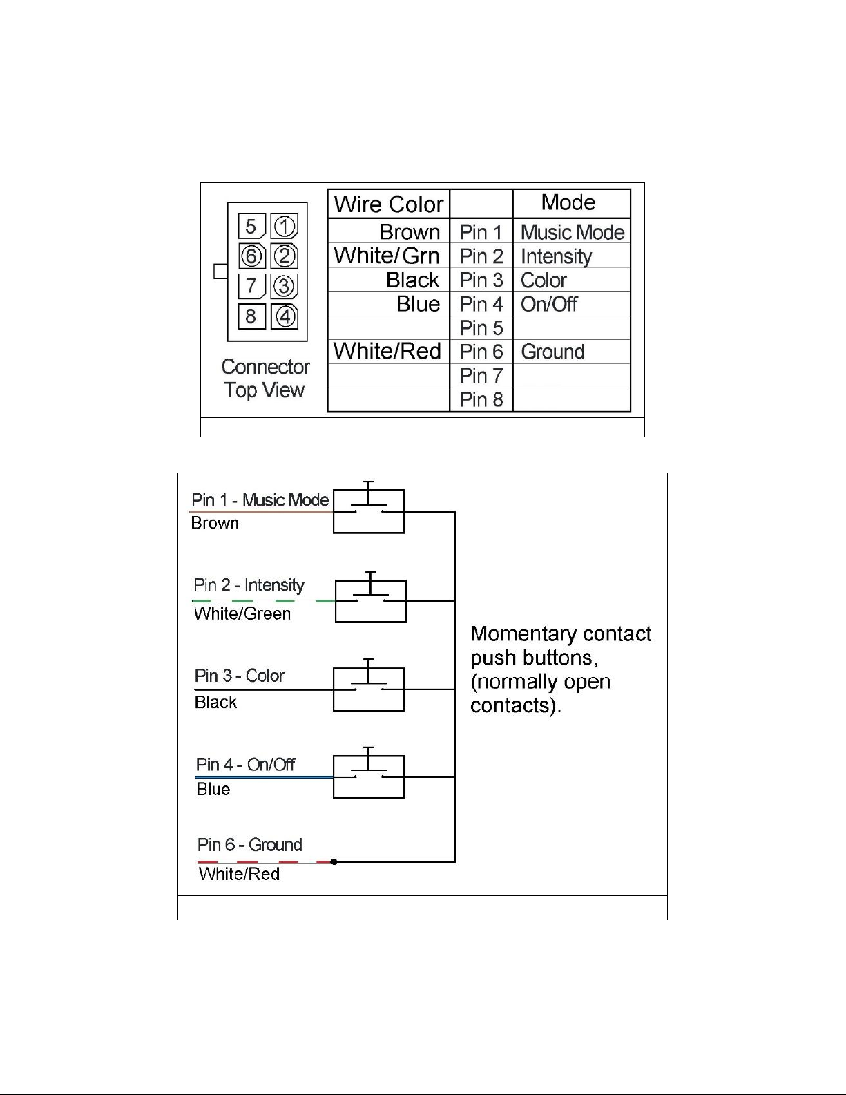
The plug labeled SW is available to accept an optional harness for you to wire in momentary contact push button(s) to
operate the RBG-BIM in a stand-alone mode without the need for an HDX/RTX system connected.
You can rig up a small panel with one, two, or all four buttons of your choice
The switches are ground triggered.
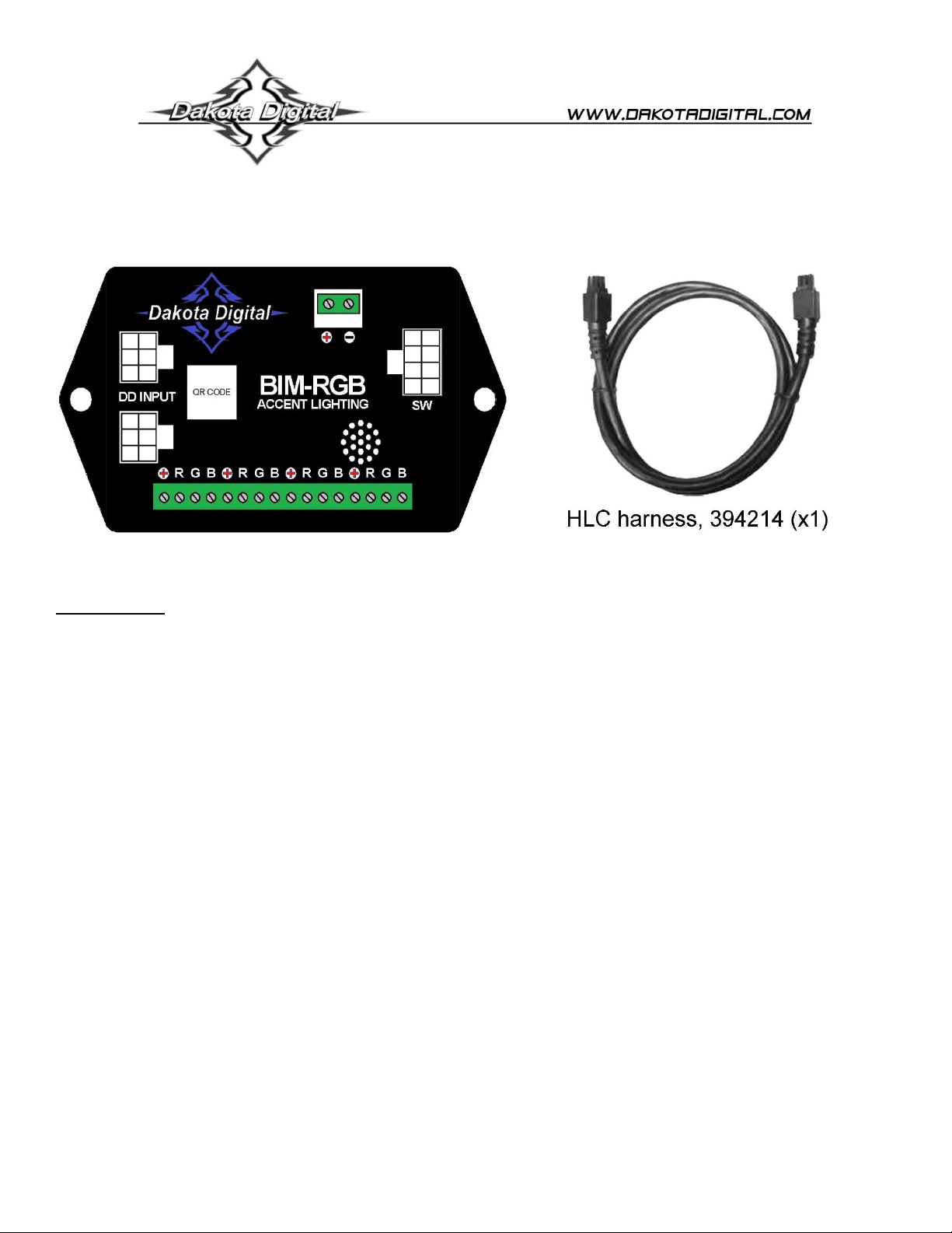
The optional harness from sales is part number 394183.
The switch harness can offer four operational modes:
1. Power On and Off
2. Color Change
3. Color Intensity
4. Music Mode On and Off
*Note: When the RGB-BIM is synced to an HDX/RTX system, the color and intensity buttons have no affect.
ON/OFF
Tapping the On/Off switch can toggle the LED lights on or off, in stand-alone or synced modes.
If any color or intensity changes are made with optional switches, pressing and holding the On/Off switch for longer than 3
seconds will save those settings back to the RGB-BIM. The LED lights will go out indicating the changes were saved.
One can reset the RBG-BIM back to default settings, but this will also need the Music button wired up.
Press and hold the On/Off button, wait for the LEDs to go out, then tap the Music button.
Release the On/Off button and the RGB-BIM will be reset to factory colors and intensity.
The factory mode will set the RGB-BIM to sync with an HDX/RTX system
COLOR
Tapping the Color switch will change the color through the different color options in stand-alone mode.
When the RGB-BIM is connected to an HDX/RTX, the Color switch can only control syncing.
Press and hold until the LEDs go out to toggle between syncing and stand alone.
To keep the RGB-BIM in stand-alone mode at power up, the SYNC setting must be turned off and saved.
INTENSITY
Tapping the Intensity switch will change through the 31 levels of intensity.
Holding the Intensity switch will automatically switch intensity every second.
The intensity gets brighter until it reaches the end and restarts the cycle at the lowest intensity.
The Intensity switch will not function when synced to an HDX/RTX control box.
MUSIC MODE
Tapping the Music button will enable or disable the music mode when synced or stand-alone.

8 MAN # 650810
Connections for Custom Switch Option
Wire the number of switches you would like to use to the appropriate wire color and the other end of the switch to ground.
You could wire up the On/Off switch and the Music Mode switch only, or all four switches. That is your choice.
Figure 3 shows the pin connections.
Figure 4 shows how to make connections from the harness to the switches.
Figure 3 Switch Input Connector
Figure 4 Switch Wiring

9 MAN # 650810
Troubleshooting guide:
PROBLEM
POSSIBLE CAUSE(S)
POSSIBLE SOLUTIONS(S)
LED’s not lighting up
No power to the BIM-RGB
Poor connection on the +, R, G or B
outputs
BIM-RGB is in music mode
Check power and ground connections into the BIM_RGB
Check the connections to the LED’s
In music mode the LED’s will flash on with music. Go into the settings
and make sure music mode is off. If you tap on the BIM-RGB case by
the microphone input and the LED’s flash this is most likely the
problem.
PROBLEM
POSSIBLE CAUSE(S)
POSSIBLE SOLUTIONS(S)
LED’s not flashing in music
mode
BIM-RGB is not in a location where the
microphone can pick up the music
The LED outputs are not turned on
Be sure the BIM-RGB is located where it can pick up sound from a
speaker. If you tap on the BIM-RGB case by the microphone input the
LED’s should flash. If they do this is most likely the problem
Check the On/Off setting in the app, or toggle the On/Off switch if
using the optional switch panel. If you toggle the music mode switch
the LED’s should turn on and off if no music is playing and the LED
outputs are turned on.
LED color not synchronized to
the gauge
Bad connection to the gauge
Sync mode not enable
Check the cable between the gauge and BIM-RGB. If LED’s are white
this is the default color and would indicate this may be the problem.
The module defaults to standalone mode if no message from the
gauge is detected after 10 seconds.
Check the synch setting in the app, or if using the optional switch
panel press the color switch for greater that 3 seconds to change
modes

10 MAN # 650810
Technical specifications:
Output current + outputs: 1.85 amps per output
Input current: 7.4 amps maximum
Modes: Synchronized, Standalone, Synchronized Music Mode, Standalone Music Mode
Dakota Digital system colors: Key Lime, Kryptonite, Coolant, Sage, Green Flag, Minty Fresh, Turquoise, Clear View,
Road Trip, Quenched, Denim Jacket, Nightfall, Amethyst, Garnet Pink, Candy Store, Pink Slip, Salmon, Grenadine,
Faded Red, Red Anodized, Red Lighted, Grapefruit, Trophy Gold, Traffic Cone, Staged, Log Book, Candle Light, Barn
Find, Cool White, Warm White, White, Cast Iron
Control Box Compatibility - The following versions of software (or newer) are required to function with the BIM-RGB
(Note: All RTX systems support this option):
Control Box / Dash
Minimum Software Version Required
HDX Control Box
HX02 or RX01
HDX Gauge Cluster
Any
RTX Control Box
RX01
RTX Gauge Cluster
Any

11 MAN # 650810
Notes:

12 MAN # 650810
SERVICE AND REPAIR
DAKOTA DIGITAL offers complete service and repair of its product line. In addition, technical support is
available to help you work through any questions or problems you may be having installing one of our
products. Please read through the Troubleshooting Guide. There, you will find the solution to most problems.
For additional support, please visit www.dakotadigital.com. A “Product Support” link will be found at the
bottom of the home page.
Should you ever need to send the unit back for repairs, please call our technical support line, (605) 332-
6513, to request a Return Merchandise Authorization number.
•Package the product in a good quality box along with plenty of packing material.
•Ship the product by a common carrier with tracking abilities.
•Be sure to include the RMA number on the package.
•Include a complete description of the problem, with RMA number, your full name and address (street
address preferred), and a telephone number where you can be reached during the day.
•Any returns for warranty work must include a copy of the dated sales receipt from your place of
purchase.
•Send no money. We will contact you for payment.
Dakota Digital 24 Month Warranty
DAKOTA DIGITAL warrants to the ORIGINAL PURCHASER of this product that should it, under normal
use and condition, be proven defective in material or workmanship within 24 MONTHS FROM THE DATE OF
PURCHASE, such defect(s) will be repaired or replaced at Dakota Digital’s option.
This warranty does not cover nor extend to damage to the vehicle’s systems and does not cover
removal or reinstallation of the product.
This Warranty does not apply to any product or part thereof which in the opinion of the Company has
been damaged through alteration, improper installation, mishandling, misuse, neglect, or accident.
This Warranty is in lieu of all other expressed warranties or liabilities.
Any implied warranties, including any implied warranty of merchantability, shall be limited to the
duration of this written warranty.
Any action for breach of any warranty hereunder, including any implied warranty of merchantability,
must be brought within a period of 24 months from date of original purchase.
No person or representative is authorized to assume, for Dakota Digital, any liability other than
expressed herein in connection with the sale of this product.
WARNING: This product can expose you to chemicals including lead, which is known to the State of
California to cause cancer and birth defects or other reproductive harm. For more information go to
www.P65Warnings.ca.gov
Table of contents
Other Dakota Digital Controllers manuals

Dakota Digital
Dakota Digital PAC-2700 User manual

Dakota Digital
Dakota Digital PAC-1300A User manual

Dakota Digital
Dakota Digital PAC-3200 User manual

Dakota Digital
Dakota Digital CMD-2000 Series User manual

Dakota Digital
Dakota Digital PAC-3500 User manual

Dakota Digital
Dakota Digital PAC-2750 User manual

Dakota Digital
Dakota Digital PAC-2000 User manual
Popular Controllers manuals by other brands

GeoVision
GeoVision GV-CS1320 quick start guide

Giacomini
Giacomini R473 Series manual

Linak
Linak TECHLINE LA25 Connection diagram

Regulus
Regulus SRS3 instruction manual

Honeywell
Honeywell MS7503A2023 installation instructions

Simons Voss Technologies
Simons Voss Technologies SmartRelais-3-Controller quick guide