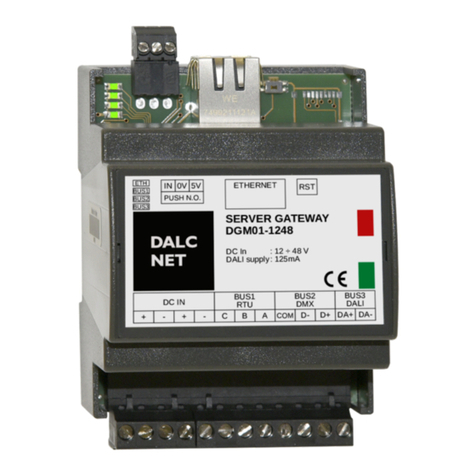
DALCNET DGM02 Application guide

DGM02
Device Manual
Made in Italy
DALCNET S.r.l.
36077 Altavilla Vicentina (VI) –Italy
Via Lago di Garda, 22
Tel. +39 0444 1836680
www.dalcnet.com –info@dalcnet.com
Rev. 06/12/2022 - Pag. 1/32
FEATURES
SERVER GATEWAY
POWER INPUT: 12-24-48 Vdc
ETHERNET BUS: 10/100Mbit
MODBUS BUS: range baud rate 9600 –250000
DMX BUS: 1 universe DMX512
DALI BUS: 1 DALI line –integrated DALI bus power supply
For the always updated manual, consult our website: www.dalcnet.com or the QR on the product
TECHNICAL SPECIFICATIONS
DGM02-1248
Supply voltage
12 / 24 / 48 Vdc
Input current
550mA max
Nominal Power1
typ
max
@12V
160 mA (1.92W)
550 mA (6.60W)
@24V
80 mA (1.92W)
260 mA (6.24W)
@48V
50 mA (2.40W)
150 mA (7.20W)
PoE1
min2
typ
max
@46.5V
40 mA (1.9W)
100 mA (4.65W)
170 mA (7.9W)
ETHERNET
10 / 100 Mbit baseT FULL DUPLEX AUTO NEGOTIATION
MODBUS RTU
RS-485, BAUD RATE da 9600 a 250000
DMX
512 CHANNELS
DALI
64 ADDRESS
Integrated power supply: 200mA / 16Vdc
Guaranteed bus current = 200mA
Max bus current = 250mA
Storage temperature
Min: -40°C ÷ Max +60°C
Ambient temperature
Min: -40°C ÷ Max +60°C
Protection grade
IP10
Casing material
Plastic
Packaging units (pieces/units)
1pz
Mechanical dimensions
72 x 92 x 62 mm
Package dimensions
85 x 124 x 71 mm
Weight
100g
1
Values may differ by ± 5%
2
Only with BUS 3 config in NOT USE

DGM02
Device Manual
Made in Italy
DALCNET S.r.l.
36077 Altavilla Vicentina (VI) –Italy
Via Lago di Garda, 22
Tel. +39 0444 1836680
www.dalcnet.com –info@dalcnet.com
Rev. 06/12/2022 - Pag. 2/32
REFERENCE STANDARDS
EN 55035
Electromagnetic compatibility of multimedia equipment - Immunity Requirements
EN 55032
Electromagnetic compatibility of multimedia equipment - Emission Requirements
EN IEC 62368-1
Audio/video, information and communication technology equipment - Part 1: Safety requirements
EN IEC 62368-1/A11
Audio/video, information and communication technology equipment - Part 1: Safety requirements
EN IEC 62368-1/AC
Audio/video, information and communication technology equipment - Part 1: Safety requirements
IEC 62386-101 ED.2
Digital addressable lighting interface –Part 101: General requirement –System components
IEC 62386-103 ED.2
Digital addressable lighting interface –Part 103: General requirements –Control devices
IEC 62386-205 ED.23
Digital addressable lighting interface –Part 205: Particular requirements for control gear –Supply
voltage controller for incandescent lamps (device type 4)
IEC 62386-207 ED.24
Digital addressable lighting interface –Part 207: Particular requirements for control gear –LED
modules (device type 6)
IEC 62386-209 ED.25
Digital addressable lighting interface –Part 209: Particular requirements for control gear –Colour
control (device type 8)
ANSI E1.11
Entertainment Technology –USITT DMX512-A Asynchronous Serial Digital Data Transmission
Standard for Controlling Lighting Equipment and Accessories
-
MODBUS APPLICATION PROTOCOL SPECIFICATION V1.1b
3
Il DGM02 set commands for control gear DT4, compatible with the standard IEC 62386-205
4
Il DGM02 set commands for control gear DT6, compatible with the standard IEC 62386-207
5
Il DGM02 set commands for control gear DT8, compatible with the standard IEC 62386-208 (colour type Tc, colour type RGBWAF)

DGM02
Device Manual
Made in Italy
DALCNET S.r.l.
36077 Altavilla Vicentina (VI) –Italy
Via Lago di Garda, 22
Tel. +39 0444 1836680
www.dalcnet.com –info@dalcnet.com
Rev. 06/12/2022 - Pag. 3/32
WIRING DIAGRAM
WIRING 1
WIRING 2
WIRING 3
DMX wired with XLR connector
PINOUT CONNECTORS
PIN
RJ45/A (RJ45/B crossed)
RJ45/B (RJ45/A crossed)
1
White / Green
White / Orange
2
Green
Orange
3
White / Orange
White / Green
4
Blue
Blue
5
White / Blue
White / Blue
6
Orange
Green
7
White / Brown
White / Brown
8
Brown
Brown
PIN OUT PLUG-IN CONNECTORS
1
DC IN
Vin+
2
Vin-
3
Vin+
4
Vin-
5
Modbus 1
C
DMX 1
COM
6
B
D-
7
A
D+
8
Modbus 2
C
DMX 2
COM
9
B
D-
10
A
D+
11
DALI
DA+
12
DA-
RESET
BUTTON
SEE
WIRING 2
SEE
WIRING 3
SEE
WIRING 1

DGM02
Device Manual
Made in Italy
DALCNET S.r.l.
36077 Altavilla Vicentina (VI) –Italy
Via Lago di Garda, 22
Tel. +39 0444 1836680
www.dalcnet.com –info@dalcnet.com
Rev. 06/12/2022 - Pag. 4/32
ONBOARD LED
LED
FUNCTION
ON
BLINK
OFF
LED1
(First from left)
Ethernet
Wired and
communicating via
ethernet
Wired with ethernet
Not wired
LED2
BUS1(RTU/ DMX)
Connected with
communication
Connected with no
communication (only
RTU)
BUS1 not enabled
LED3
BUS2(DMX/RTU)
Connected with
communication
Connected with no
communication (only
RTU)
BUS2 not enabled
LED4
(First from right)
BUS DALI
Connected with
communication
Connected with no
communication
DALI BUS not enabled. BUS
power off
RESET BUTTON
Device Restart: Press the reset button for less than 2 seconds.
Factory settings: Press the reset button for more than 2 seconds, all 4 signaling LEDs must light up progressively from right to
left.
POWER OVER ETHERNET (POE)
The device is able to operate also with PoE power supply.
To enable this power supply, simply move the PoE selector upwards.
PoE On
PoE Off (factory setting)
NOTE: Before connecting the device to a PoE switch or injector, disconnect any other power sources from the DC IN + and DC IN-
terminals.

DGM02
Device Manual
Made in Italy
DALCNET S.r.l.
36077 Altavilla Vicentina (VI) –Italy
Via Lago di Garda, 22
Tel. +39 0444 1836680
www.dalcnet.com –info@dalcnet.com
Rev. 06/12/2022 - Pag. 5/32
TECHNICAL NOTE
INSTALLATION:
•CAUTION: The product may only be connected and installed by a qualified electrician. All applicable regulations, legislation,
and building codes must be observed. Incorrect installation of the product can cause irreparable damage to the product
and the connected LEDs.
•Maintenance must be performed only by a qualified electrician in compliance with current regulations.
•The product must be installed inside a switchgear/controlgear cabinet and/or junction box protection against overvoltage.
•The product must be installed in a vertical or horizontal position with the label/top cover facing upwards or vertically.
Other positions are not permitted. The bottom position is not permitted (label/top cover facing down).
•Keep separated 230Vac (LV) circuits and not SELV circuit from safety extra low voltage (SELV) circuit and from any
connection with this product. It is absolutely forbitten to connect, for any reason whatsoever, directly or indirectly, the
230Vac mains voltage to the product (terminal block of BUS included).
•The product must be dissipated correctly.
•The use of the product in harsh environments could limit the output power.
POWER SUPPLY
•Only use SELV power supplies with limited current for device power supply, short circuit protection and the power must
be dimensioned correctly.
In the case of power supplies equipped with ground terminals, it is mandatory to connect ALL protective ground points
(PE= Protection Earth) to a properly and certified protection earth.
•The connection cables between the very low voltage power source and the product must be properly dimensioned and
must be insulated from any wiring or part at non-SELV voltage. Use double insulated cables.
•Dimension the power of the power supply in relation to absorption of device. In case the power supply is oversized
compared to the maximum absorbed current, insert a protection against over-current between the power supply and the
device.
COMMAND
•The length of the cables connecting between the local commands (N.O. Push button, 0-10V, 1-10V, Potentiometer or
other) and the product must be less than 10m. The cables must be properly dimensioned and must be insulated from any
non-SELV wiring or voltage. It is recommended to use double insulated cables, if deemed appropriate also shielded.
•The length and type of cables connecting to the bus (DMX, Modbus, DALI, Ethernet or other) must comply with the
specifications of the respective protocols and the regulations in force. They must be insulated from any non-SELV wiring
or voltage parts. It is recommended to use double insulated cables.
•ALL device and control signal connected to the local command “N.O. Push button”, they must not supply any type of
voltage.
•ALL device and control signal connect at the BUS (DMX512, Modbus, DALI, Ethernet or other) and to the local command
(N.O. Push button or other) must be SELV type (the device connected must be SELV or supply SELV signal).

DGM02
Device Manual
Made in Italy
DALCNET S.r.l.
36077 Altavilla Vicentina (VI) –Italy
Via Lago di Garda, 22
Tel. +39 0444 1836680
www.dalcnet.com –info@dalcnet.com
Rev. 06/12/2022 - Pag. 6/32
SUMMARY SERVER GATEWAY
SERVER GATEWAY ...................................................................................................................................................................................7
HOME PAGE ............................................................................................................................................................................................8
Device info .........................................................................................................................................................................................8
web side led info .................................................................................................................................................................................8
WEB INTERFACE ......................................................................................................................................................................................9
SECTION: CHANNEL ...............................................................................................................................................................................10
SECTION: BUS CONFIGURATION .............................................................................................................................................................11
Bus 1 ...............................................................................................................................................................................................11
Bus 2 ...............................................................................................................................................................................................11
Bus 3 ...............................................................................................................................................................................................12
SECTION: DALI GLOBAL SETTINGS –BUS 3..............................................................................................................................................13
SETTINGS: DALI CONFIG –BUS 3 ...........................................................................................................................................................14
Addressing........................................................................................................................................................................................14
Identification of addressed devices ......................................................................................................................................................14
Address change from the devices already addressed ..............................................................................................................................15
Associating a group with a dali address ................................................................................................................................................15
Removing a group .............................................................................................................................................................................16
State of the dali node.........................................................................................................................................................................16
DALI CONTROLLER –BUS 3 ....................................................................................................................................................................17
DMX512 GLOBAL SETTINGS & RS485 –DMX MASTER (BUS 1 & BUS 2)........................................................................................................18
DMX512 GLOBAL SETTINGS & RS485 –DMX SLAVE (BUS 1 & BUS 2) ..........................................................................................................19
MODBUS MASTER & RS485 –MODBUS RTU MASTER (BUS 1 & BUS 2) .........................................................................................................20
MODBUS SLAVE & RS458 –MODBUS RTU SLAVE (BUS 1 & BUS 2) ..............................................................................................................21
SECTION: DIAGNOSTIC –LOG ................................................................................................................................................................22
SECTION: DIAGNOSTIC –LOG CONFIGURATION .......................................................................................................................................22
NETWORK .............................................................................................................................................................................................23
LOGIN INFO ..........................................................................................................................................................................................24
Edit credentials, procedure: ................................................................................................................................................................24
FIRMWARE updates ................................................................................................................................................................................25
Firmware upload, procedure: ..............................................................................................................................................................25
sACN (ETHERNET)..................................................................................................................................................................................26
TCP TELNET (ETHERNET) ........................................................................................................................................................................27
Data level .........................................................................................................................................................................................27
Power-on: Default levels ....................................................................................................................................................................28
Query dali device type........................................................................................................................................................................28
Set rgbwaf dali dt8 colour levels ..........................................................................................................................................................28
Query rgbwaf dali dt8 colour levels ......................................................................................................................................................29
Set color tc level ...............................................................................................................................................................................29
Query color tc levels ..........................................................................................................................................................................30
Fade engine ......................................................................................................................................................................................30
ART-NET 4 (ETHERNET) ..........................................................................................................................................................................31
Implemented packet ..........................................................................................................................................................................31
MODBUS TCP (ETHERNET) ......................................................................................................................................................................32
Implemented packet ..........................................................................................................................................................................32

DGM02
Device Manual
Made in Italy
DALCNET S.r.l.
36077 Altavilla Vicentina (VI) –Italy
Via Lago di Garda, 22
Tel. +39 0444 1836680
www.dalcnet.com –info@dalcnet.com
Rev. 06/12/2022 - Pag. 7/32
SERVER GATEWAY
The DGM02 device converts information between multiple protocols in real time. It is able to acquire information from the ethernet
network and from one or more buses (configured as reception buses), transmitting and converting them to the ethernet network
and the buses configured as transmission.
The 512 channels of the buffer are transmitted entirely on the DMX512A bus.
On the DALI bus the first 64 channels of the buffer are transmitted as 64 short addresses, or the first 16 channels as 16 group
addresses, or 1 channel as broadcast, only to the nodes that change value.
It is also possible to control DALI DT4 / DT6 / DT8-RGBW / DT8-TW devices through specific Telnet commands.
The first 480 channels of the buffer are transmitted on the MODBUS RTU bus to 80 Modbus devices (ID 1..80) of 6 registers each.
Through any control unit that has an Ethernet connection it becomes possible to control a total of 512 levels of light intensity and
to control different devices (DMX512A, DALI, MODBUS) without having to know in detail the operation of the relative protocols.

DGM02
Device Manual
Made in Italy
DALCNET S.r.l.
36077 Altavilla Vicentina (VI) –Italy
Via Lago di Garda, 22
Tel. +39 0444 1836680
www.dalcnet.com –info@dalcnet.com
Rev. 06/12/2022 - Pag. 8/32
HOME PAGE
DEVICE INFO
In the “HOME” screen it is possible to view the information of the device in use such as:
Dashboard version, Firmware version, TCP / IP stack version.
On this page you can select the following sections:
LOGOUT, to exit the Web Server of the device in use.
MENU ', by clicking on the pop-up menu you can access the device configuration pages.
oBUS section: this section contains the pages for managing protocols, such as DALI, DMX and MODBUS, and
managing the devices connected to the DALI network;
oSETTINGS Section: this section contains the pages for configuring the IP address and for setting up the network
and BUS protocols.
WEB SIDE LED INFO
STEADY GREEN: communication is active
BLINKING YELLOW: no communication via BUS or BUS not activated

DGM02
Device Manual
Made in Italy
DALCNET S.r.l.
36077 Altavilla Vicentina (VI) –Italy
Via Lago di Garda, 22
Tel. +39 0444 1836680
www.dalcnet.com –info@dalcnet.com
Rev. 06/12/2022 - Pag. 9/32
WEB INTERFACE
For supervision and configuration, the Gateway provides a web interface accessible via a browser at the IP address of the device
(default IP 192.168.1.4).
By clicking on the top menu, you can view the device settings (accessible only to Admin users):
Channels: in this page it is possible to configure the dimming values of the channels
with the relative fader (not visible if in DALI CONFIG mode);
Bus Configuration: in this page it is possible to configure the settings for each single
physical bus on the DGM02;
Dali global settings: in this page it is possible to configure the settings for the DALI
bus (modifiable only if in DALI CONFIG mode);
DALI Config: on this page you can configure the DALI devices, address them and
assign membership to groups (not visible if in DALI CONTROLLER mode);
DALI controller: on this page it is only possible to view the addressed DALI devices
and their belonging to the groups (not visible if in DALI CONFIG mode);
DMX512 Global Settings: in this page it is possible to configure the DMX512 timing
settings (not visible if in DALI CONFIG mode or RS485 Bus not enabled);
RS485: on this page you can configure the settings for the sending speed of the
RS485 packet (not visible if in DALI CONFIG mode or RS485 Bus not enabled);
MODBUS Master: on this page you can configure the settings for sending the master
MODBUS RTU packet (not visible if in DALI CONFIG mode or if the master MODBUS
RTU BUS is not enabled);
MODBUS Slave: on this page you can configure the settings for sending the MODBUS
RTU slave packet (not visible if in DALI CONFIG mode or if the MODBUS RTU slave
BUS is not enabled);
Network: on this page you can configure the settings to change and manage the IP
address, the Netmask and view the MAC Address;
Login Settings: on this page it is possible to configure the settings for modifying and
managing the LOGIN USER and PASSWORD;
sACN: on this page you can configure the settings for enabling or disabling the
protocol;
Telnet: on this page you can configure the settings for enabling or disabling the
protocol and sending times;
ARTNet: on this page you can configure the settings for enabling or disabling the
protocol;
MODBUS TCP Slave: on this page you can configure the settings for enabling or
disabling the protocol;
Firmware Update: on this page it is possible to configure how the device Firmware
is updated;
Log: the product logs are stored on this page;
Log Configuration: on this page you can configure the settings for managing the
LOGs.

DGM02
Device Manual
Made in Italy
DALCNET S.r.l.
36077 Altavilla Vicentina (VI) –Italy
Via Lago di Garda, 22
Tel. +39 0444 1836680
www.dalcnet.com –info@dalcnet.com
Rev. 06/12/2022 - Pag. 10/32
SECTION: CHANNEL
The DGM02 has a WebApp for the supervision and regulation of all the channels available in the various DALI, DMX, MODBUS
protocols, which can be used from any device equipped with a compatible browser.
By default, a window for managing 16 channels is displayed. Using the "NUMBER OF SLIDERS" icon you can choose how many
channels to see in a single screen (no more than 200) and, thanks to the "DISPLAY MODE" icon, organize the slides of the channels
horizontally or vertically.
It is also possible to scroll through all 512 available channels by clicking on the “GO TO FIRST”, “GO TO LAST” buttons or by
advancing one or eight channels at a time by clicking on the “+1” or “+8” icons. The same is true if you want to go back one or
eight channels at a time by clicking on the icons "-1" or "-8"
Thanks to the “MASTER” slide it is possible to set all the channels to the same dimming value.
This graphic allows you to view under each slider whether or not it belongs to one of the three available buses with relative offset
and set range (for more information see "BUS CONFIGURATION").
NOTE: To use the available services and applications correctly, it is necessary to use a browser compatible with the technologies:
CSS-3, JS, XHR, CORS, JSON, ArrayBuffer.
Compatible browsers are: Microsoft Edge v. 16, Google Chrome v. 66, Mozilla Firefox v. 57, Safari v. 12.1, Opera v. 53 or higher.
Microsoft
Edge
v. 16+
Google
Chrome
v. 66+
Mozilla
Firefox
v. 57+
Apple
Safari
v. 12.1+
Opera
v. 53+

DGM02
Device Manual
Made in Italy
DALCNET S.r.l.
36077 Altavilla Vicentina (VI) –Italy
Via Lago di Garda, 22
Tel. +39 0444 1836680
www.dalcnet.com –info@dalcnet.com
Rev. 06/12/2022 - Pag. 11/32
SECTION: BUS CONFIGURATION
BUS 1
BUS 1 is related to the first RS485 port.
You can set this port in the following configurations:
Not Set
RS485 MODBUS RTU master
RS485 MODBUS RTU slave
DMX512 master
DMX512 slave
In this menu it is possible to assign the "OFFSET" and the "CHANNELS RANGE" to the BUS
1 channels.
The OFFSET allows you to assign the number of the starting slide to the first channel of BUS
1.
The CHANGE RANGE allows you to set the number of channels you want to use in BUS 1.
The BUS can be disabled by means of the “MUTE” flag or by setting the bus configuration in
“NOT SET”.
BUS 2
BUS 2 is related to the second RS485 port.
You can set this port in the following configurations:
Not Set
RS485 MODBUS RTU master
RS485 MODBUS RTU slave
DMX512 master
DMX512 slave
In this menu it is possible to assign the "OFFSET" and the "CHANNELS RANGE" to the BUS
2 channels.
The OFFSET allows you to assign the number of the starting slide to the first channel of BUS
2.
The CHANGE RANGE allows you to set the number of channels you want to use in BUS 2.
The BUS can be disabled by means of the “MUTE” flag or by setting the bus configuration in
“NOT SET”.

DGM02
Device Manual
Made in Italy
DALCNET S.r.l.
36077 Altavilla Vicentina (VI) –Italy
Via Lago di Garda, 22
Tel. +39 0444 1836680
www.dalcnet.com –info@dalcnet.com
Rev. 06/12/2022 - Pag. 12/32
BUS 3
Bus 3 is related to the third BUS port of the product. The DALI protocols.
You can set this port in the following configurations:
Not Set
DALI controller
DALI config
In this menu it is possible to assign the "OFFSET" and "CHANNELS RANGE" of the 64 DALI
nodes to the BUS 3 channels.
The “DALI channels offset” allows you to assign the number of the starting slide to the first
DALI address.
The “DALI channels range” allows you to set the number of channels you want to use in
BUS 3.
The BUS can be disabled by means of the “MUTE” flag or by setting the bus configuration in
“NOT SET”. With these functions you disable the bus and turn off the power supply on the
DALI bus.
NOTE: when addressing DALI devices in DALI config mode, it is recommended to set the range to 64, maximum value and only
after returning to the DALI Controller configuration and addressing the devices change the range to the desired value.
After modifying the settings, click on the “APPLY” button at the top right, otherwise the changes will be lost.
On the other hand, with the “CLEAR” button the changes are cancelled.

DGM02
Device Manual
Made in Italy
DALCNET S.r.l.
36077 Altavilla Vicentina (VI) –Italy
Via Lago di Garda, 22
Tel. +39 0444 1836680
www.dalcnet.com –info@dalcnet.com
Rev. 06/12/2022 - Pag. 13/32
SECTION: DALI GLOBAL SETTINGS –BUS 3
Only in Dali config mode it is possible to send and modify the commands of the DALI global settings pop-up menu which are:
“TRANSMIT AS”:
o“Address”: send address commands
o“Group”: send group commands
o“Broadcast”: send broadcast commands
“SEND COMMAND OFF INSTEAD OF DAPC0“: sends the DALI OFF command instead of the DAPC command to 0;
“SYSTEM FAILURE LEVEL “: send the System Failure Level command in broadcast;
“POWER ON LEVEL “: sends the Power On Level command in broadcast;
“FADE TIME “: sends the Set Fade Time command in broadcast;
“DT8 MANAGEMENT “: enables the management of DT8s;
“SYSTEM FAILURE COLOR “: sends the System Failure Colour command for RGBW components;
“POWER ON COLOR “: sends the Power On Colour command for RGBW components;
NOTE:
Only by pressing “APPLY” are the DALI commands sent.
To unlock the configuration of the other buses, put the DALI bus in DALI Controller mode.

DGM02
Device Manual
Made in Italy
DALCNET S.r.l.
36077 Altavilla Vicentina (VI) –Italy
Via Lago di Garda, 22
Tel. +39 0444 1836680
www.dalcnet.com –info@dalcnet.com
Rev. 06/12/2022 - Pag. 14/32
SETTINGS: DALI CONFIG –BUS 3
NOTE: before proceeding with the addressing and configuration of the DALI devices, it is necessary to set BUS 3 in
DALI Config mode.
ADDRESSING
By clicking on "DALI config" from the pop-up menu, we enter the DALI device addressing interface.
At the top right are the following commands:
"SCAN": performs the acquisition of DALI nodes already addressed;
"ADDRESS ALL": performs the addressing of all DALI nodes, the address devices will be displayed in a list;
"REMOVE ALL": removes the addressing to all DALI nodes.
NOTE: before making a complete addressing of the system it is necessary to send a “REMOVE ALL” command.
IDENTIFICATION OF ADDRESSED DEVICES
After addressing, it is possible to flash the node just addressed, so that it can be visually identified.

DGM02
Device Manual
Made in Italy
DALCNET S.r.l.
36077 Altavilla Vicentina (VI) –Italy
Via Lago di Garda, 22
Tel. +39 0444 1836680
www.dalcnet.com –info@dalcnet.com
Rev. 06/12/2022 - Pag. 15/32
ADDRESS CHANGE FROM THE DEVICES ALREADY AD DRESSED
To change the address of the single DALI node, previously addressed, it is necessary to enter the new node value (eg from 0 to
63) to the right of the flashing button of the node itself and click the "APPLY" button which will appear immediately on the right.
ASSOCIATING A GROUP WITH A DALI ADDRESS
By clicking on one of the 16 boxes depicting the available groups (ie from 0 to 15) it is possible to associate the desired address
to a DALI Group. Subsequently, by pressing the “APPLY” button that appears at the top, the command is sent on the DALI BUS.
As confirmation of the assignment of the address to the group, the box changes from red to blue

DGM02
Device Manual
Made in Italy
DALCNET S.r.l.
36077 Altavilla Vicentina (VI) –Italy
Via Lago di Garda, 22
Tel. +39 0444 1836680
www.dalcnet.com –info@dalcnet.com
Rev. 06/12/2022 - Pag. 16/32
REMOVING A GROUP
By clicking on one of the 16 boxes depicting the available groups (ie from 0 to 15) it is possible to remove the desired address
from a DALI Group. Subsequently, by pressing the “APPLY” button that appears at the top, the command is sent on the DALI BUS.
Removal from the G3 group of the A0 address
Removal took place
STATE OF THE DALI NODE
The status of the DALI node is displayed in the outline of the button depicting the address number, and is as follows:
Black: node present and off
Yellow: node present and switched on
Red: node present but not responding correctly (LAMP FAILURE)

DGM02
Device Manual
Made in Italy
DALCNET S.r.l.
36077 Altavilla Vicentina (VI) –Italy
Via Lago di Garda, 22
Tel. +39 0444 1836680
www.dalcnet.com –info@dalcnet.com
Rev. 06/12/2022 - Pag. 17/32
DALI CONTROLLER –BUS 3
In DALI Controller mode the device transmits the DALI channels according to an algorithm that updates only the nodes that change
intensity value.
In this way, only the intensity change command is sent to the concerned DALI node.
By selecting the NODES item, it is possible to see the nodes addressed;
Instead by selecting the GROUPS item, it is possible to see the groups to which the nodes belong.

DGM02
Device Manual
Made in Italy
DALCNET S.r.l.
36077 Altavilla Vicentina (VI) –Italy
Via Lago di Garda, 22
Tel. +39 0444 1836680
www.dalcnet.com –info@dalcnet.com
Rev. 06/12/2022 - Pag. 18/32
DMX512 GLOBAL SETTINGS & RS485 –DMX MASTER (BUS 1 & BUS 2)
Setting BUS 1 (or BUS 2) as DMX512 Master in the pop-up menu activates the DMX512 GLOBAL SETTINGS and RS485 sections.
The fields displayed in the RS485 section for Bus 1 (or Bus 2) are:
"Baud rate": only 250000;
"Stop bit" 2 bits;
“Parity” none;
A universe of 512 channels can be received on both buses BUS1 and BUS2.
The fields displayed in the DMX512 GLOBAL SETTINGS section for Bus 1 (or Bus 2) are:
"Minimum Scan Time";
"Maximum Scan Time";
"Minimum RX Break Pulse Duration [us]"
“Maximum RX Break Pulse Duration [us]”;

DGM02
Device Manual
Made in Italy
DALCNET S.r.l.
36077 Altavilla Vicentina (VI) –Italy
Via Lago di Garda, 22
Tel. +39 0444 1836680
www.dalcnet.com –info@dalcnet.com
Rev. 06/12/2022 - Pag. 19/32
DMX512 GLOBAL SETTINGS & RS485 –DMX SLAVE (BUS 1 & BUS 2)
Setting BUS 1 (or BUS 2) as DMX512 Slave in the pop-up menu activates the DMX512 GLOBAL SETTINGS and RS485 sections.
The fields displayed in the RS485 section for Bus 1 (or Bus 2) are:
"Baud rate", only 250000;
"Stop bit" 2 bit;
"Parity" no-one.
A universe of 512 channels can be received on both buses BUS1 and BUS2.
The fields displayed in the DMX512 GLOBAL SETTINGS section for Bus 1 (or Bus 2) are:
"Minimum Scan Time";
"Maximum Scan Time";
"Minimum RX Break Pulse Duration [us]"
“Maximum RX Break Pulse Duration [us]”;

DGM02
Device Manual
Made in Italy
DALCNET S.r.l.
36077 Altavilla Vicentina (VI) –Italy
Via Lago di Garda, 22
Tel. +39 0444 1836680
www.dalcnet.com –info@dalcnet.com
Rev. 06/12/2022 - Pag. 20/32
MODBUS MASTER & RS485 –MODBUS RTU MASTER (BUS 1 & BUS 2)
Setting BUS 1 (or BUS 2) as MODBUS RTU Master in the pop-up menu activates the RS485 sections and the MODBUS RTU
Master.
The fields displayed in the RS485 section for Bus 1 (or Bus 2) are:
"Baud rate";
"Stop bit";
"Parity".
The fields displayed in the MODBUS RTU Master section for Bus 1 (or Bus 2) are:
"Minimum Scan Time";
"Maximum Scan Time";
"RX timeout";
"TxAs80idOf6".
The information is transmitted to 80 slaves (ID 1...80).
A group of 6 channels is sent to each slave:
ID1: channels 1 to 6 are sent in registers 0 to 5
ID2: channels 7 to 12 are sent in registers 0 to 5
...
ID80: channels from 475 to 480 are sent in registers 0 to 5
This manual suits for next models
1
Table of contents
Other DALCNET Gateway manuals