DALCNET DGM01 Parts list manual

DGM01 – SERVER GATEWAY – FW 3.0
Gateway ETHERNET-MODBUS-DMX512A-DALI
Function manual
Made in Italy
Rev. 2016-09-19
ag. 1/22
FEATURES
• Power Supply 12/24/48 Vdc
• Bus ETHERNET 10/100 Mbi
• Bus Modbus RTU, from 9600 o 250K baud
• Bus DMX 512 512 slo s NSC, SIP, RDM
• Bus DALI 64 channels, bui in
125mA power supply
➔For the whole and updated Device Manual refer to producer's website: http://www.dalcnet.com
Variants
CODE Supply
Vol age
BUS1 BUS2 BUS3
DGM01-1248 12/24/48V DC Modbus RTU RS485 /
DMX512 Modbus RTU RS485 / DMX512 DALI wi h supply
DGM01-1248-NDS 12/24/48V DC Modbus RTU RS485 /
DMX512 Modbus RTU RS485 / DMX512 DALI wi hou supply
Ex ernal DALI supply required
Technical Specifications
Su ly Voltage min: 10.8 Vdc .. max: 52.8 Vdc
In ut Current
voltage min ty * max
@ 12Vdc 110mA (1,2W) 320mA (3,84W)
500mA
@ 24Vdc 60mA (1,44W) 160mA (3,84W)
@ 48Vdc 40mA (1,92W) 80mA (3,84W)
*ethernet and all bus at full load
Storage tem erature min: -40 max: +60 °C
Ambient tem erature min: -10 max: +40 °C
Protection Grade ALUMINIUM BOX: IP20 - PLASTIC BOX IP10
Weigth ALUMINIUM BOX: 230g - PLASTIC BOX 125g
Mechanical dimensions ALUMINIUM BOX: 105x70x47 - PLASTIC BOX: 72x92x62 mm DIN RAIL 4mod.
Packaging dimensions 85 x 124 x 71 mm
ETHERNET 10/100 Mbit baseT FULL DUPLEX AUTO NEGOTIATION
MODBUS RTU RS-485, from 9600 to 250kbaud
DMX Max 512 channels (it de ends on the wiring)
o en fail safe - short fail safe
DALI Max 64 channels, buit-in 125mA ower su ly
Server Gateway
CONTROLLERS
DALCNET S.r.l.
Registered office: via Meucci, 35 - 36040 Brendola (VI) - Italy
Headquarters: via Meucci, 35 - 36040 Brendola (VI) - Italy
Tel. + 39 0444 1836680/1867452 Fax. + 39 0444 1867453
VAT: IT-04023100235
info@dalcnet.com www.dalcnet.com

DGM01 – SERVER GATEWAY – FW 3.0
Gateway ETHERNET-MODBUS-DMX512A-DALI
Function manual
Made in Italy
Rev. 2016-09-19
ag. 2/22
Reference Standards
EN 55022:2010 Information technology equi ment - Radio disturbance characteristics - Limits and methods of measurement
EN 55024:2010 Information technology equi ment - Immunity characteristics - Limits and methods of measurement
EN 60950-1:2006 + A1:2010 +
A2:2013 + A11:2009 + A12: 2011
Information technology equi ment - Safety
IEC/EN 62386-101 Digital addressable lighting interface - Part 101: General requirements - System
IEC/EN 62386-102 Digital addressable lighting interface - Part 102: General requirements - Control gear
IEC/EN 62386-207 Digital addressable lighting interface - Part 207: Particular requirements for control gear - LED
modules (device ty e 6)
ANSI E 1.3 Entertainment Technology - Lighting Control Systems - 0 to 10V Analog Control S ecification
ANSI E1.11 Entertainment Technology - USITT DMX512-A - Asynchronous Serial Digital Data Transmission
Standard for Controlling Lighting Equi ment and Accessories
ANSI E1.20 Entertainment Technology-RDM-Remote Device Management over USITT DMX512 Networks
- MODBUS APPLICATION PROTOCOL SPECIFICATION V1.1b
Technical Notes
Ins alla ion:
• Ins alla ion and main enance mus be performed only by qualified personnel in compliance wi h curren regula ions.
• The produc mus be ins alled inside an elec rical panel pro ec ed agains overvol ages.
• The produc mus be ins alled in a ver ical or horizon al posi ion wi h he cover / label upwards or ver ically; o her posi ions are no permi ed.
I is no permi ed he bo om-up posi ion (wi h he lower face pla e / label).
• Keep separa e he 230V circui s (LV) and no SELV circui s from safe y ex ra low vol age (SELV) and all connec ions for his produc . I 's
absolu ely forbidden o connec , for any reason, direc ly or indirec ly, he 230V mains vol age o he bus or o o her par s of he circui .
Power Supply:
• For power supply use only SELV power supplies wi h limi ed curren and shor circui pro ec ion, and of appropria ely sized power. In case of
power supplies provided wi h an ear h erminal, ALL pro ec ive ear hing poin s (PE = Pro ec ion Ear h) mus be connec ed o a valid
pro ec ion ear h.
• The connec ion cables be ween he power source and he produc mus be sized properly and should be isola ed from any wiring or live
par s no SELV. Use double insula ed cables.
Commands:
• The leng h of he connec ing cables be ween he local con rols (push bu on, 0-10V, 1-10V, po en iome er, or o her) and he produc mus be
less han 10m; he cables mus be sized properly and should be isola ed from any wiring or live par s no SELV. Use double insula ion
shielded and wis ed cables.
• The leng h and ype of he bus cables (DMX512, Modbus, DALI, E herne or o her) mus comply wi h he specifica ions defined by he
respec ive pro ocols and he respec ive regula ions; They should be isola ed from any wiring or live par s no SELV. Use shielded cables and
wis ed double insula ion.
• All devices and rela ed con rol signals o he bus (DMX512, Modbus, DALI, E herne or o her) and o he local con rols (push bu on, 0-10V,
1-10V, po en iome er, or o her) mus be SELV (connec ed devices mus be SELV or o herwise provide a SELV signal).
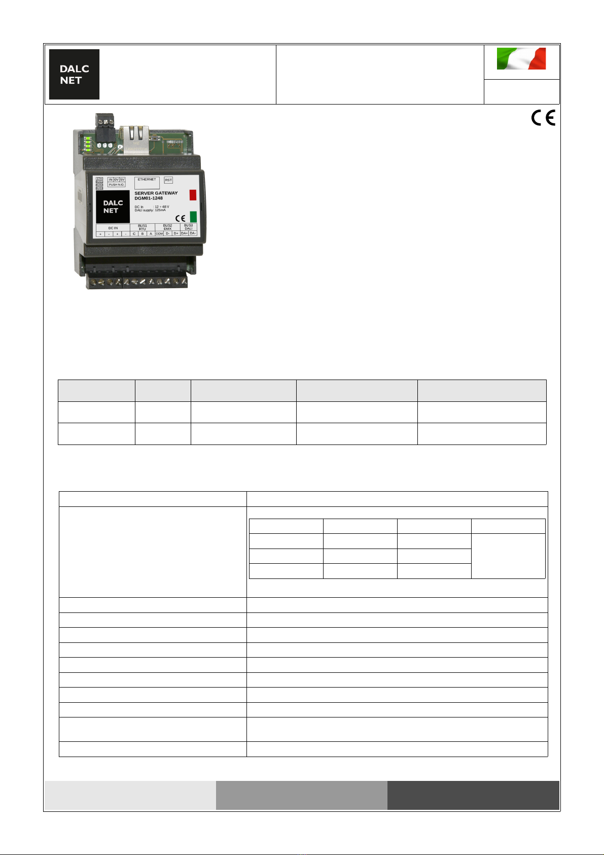
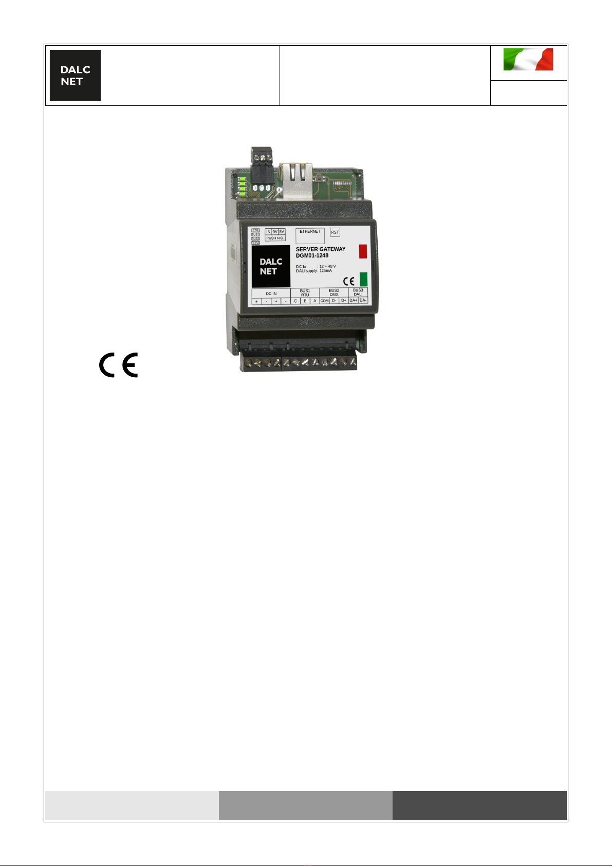
Server Gateway
CONTROLLERS
DALCNET S.r.l.
Registered office: via Meucci, 35 - 36040 Brendola (VI) - Italy
Headquarters: via Meucci, 35 - 36040 Brendola (VI) - Italy
Tel. + 39 0444 1836680/1867452 Fax. + 39 0444 1867453
VAT: IT-04023100235
info@dalcnet.com www.dalcnet.com

DGM01 – SERVER GATEWAY – FW 3.0
Gateway ETHERNET-MODBUS-DMX512A-DALI
Function manual
Made in Italy
Rev. 2016-09-19
ag. 3/22
Installation
Terminal block
Pin
1
Vin
Vin+
2 Vin-
3 Vin+
4 Vin-
5
Modbus 1
C
DMX 1
Com
6 B D-
7 A D+
8
Modbus 2
C
DMX 2
Com
9 B D-
10 A D+
11
DALI
DA+
12 DA-
ETHERNET Plug 8P8C)
Pin RJ45/A RJ45/B crossed) RJ45/B RJ45/A crossed)
1 White/Green White/Orange
2 Green Orange
3 White/Orange White/Green
4 Blue Blue
5 White/Blue White/Blue
6 Orange Green
7 White/Brown White/Brown
8 Brown Br
Configuration
RST BUTTON:
Push < 0.5s = reboot & switch to bootloader
Push > 4s = factory default
DEFAULT IP ADDRESS: 192.168.1.4
LEDs:
LED FUNCTION ON BLINK Fast blink OFF
LED1 (to ) Ethernet OK No communication - Error
LED2 BUS1 (DMX/RTU) OK No communication - Error
LED3 BUS2 (DMX/RTU) OK No communication - Error
LED4 (bottom) BUS DALI OK No communication - no ower or short circuit
Server Gateway
CONTROLLERS
DALCNET S.r.l.
Registered office: via Meucci, 35 - 36040 Brendola (VI) - Italy
Headquarters: via Meucci, 35 - 36040 Brendola (VI) - Italy
Tel. + 39 0444 1836680/1867452 Fax. + 39 0444 1867453
VAT: IT-04023100235
info@dalcnet.com www.dalcnet.com
DMX
OUT
SERVER GATEWAY
DGM01-1248
DC In
DALI supply
: 12 - 48 V
: 125mA
ETH
BUS1
BUS2
BUS3
IN 0V 5V
PUSH N.O.
ETHERNET RST
DC IN
+ - + -
BUS1
RTU
BUS2
DMX
BUS3
DALI
C B A COM D- D+ DA+ DA-
XLR
3
DALI
OUT
MODBUS
OUT
N.O. push bu on
12/24/48 Vdc

DGM01 – SERVER GATEWAY – FW 3.0
Gateway ETHERNET-MODBUS-DMX512A-DALI
Function manual
Made in Italy
Rev. 2016-09-19
ag. 4/22
LOCAL INPUT:
The device has a local in ut ( ush button normally o en) which allows the use in stand-alone mode. This function, in addition to being a
further ossibility to manage the s ot lights, is articularly useful to carry out a local test of the device and fixtures that are connected with,
making on/off/dimmer function of the s ot lights in broadcasting mode.
Button Function
PUSH Click
Double Click
Long ression (>1s) from OFF
Long ression (>1s) from ON
ON/OFF
Maximum intensity
Turn ON at 10% (night)
Dimmer UP/DOWN
1- Memory Function: The device stores its state in the event of blackout (N.O. ush button connected to 5V).
2- Eco Function: The device staru s turned off in the event of blackout (N.O. ush button connected to 0V).
3- Preset Function: The installer stores the reset status (N.O. ush button connected to 5V during installation, next to 0V).
The device starts from the reset in the event of blackout.
E.g. connecting local in uts:
Server Gateway
CONTROLLERS
SERVER GATEWAY
DGM01-1248
DC In
Range
DALI supply
: 12 ÷ 48 V
: -40 ÷ +60 °C
: 125mA
ETH
BUS1
BUS2
BUS3
IN 0V 5V
PUSH N.O.
ETHERNET RST
DC IN
+ - + -
BUS1
RTU
BUS2
DMX
BUS3
DALI
C B A COM D- D+ DA+ DA-
N.O.
Push Button
*connect to 5V = MEMORY
*connect to 0V = NO-MEM
0
4
8
C
0
4
8
C
0
4
8
C
3 2 1
INPUT 0V 5V ADDRESS
x100 x10 x1 DA+ DA- N.C.
DALI
DC IN
+-+-N.C. N.C. L1 L1 L2 L2 L3 L3
+-+-+-
OUT
LED DIMMER
DLB1248
DC In : 12-48V
Ou : CC/CV
Range : -40°C ÷ +60°C
DALCNET S.r.l.
Registered office: via Meucci, 35 - 36040 Brendola (VI) - Italy
Headquarters: via Meucci, 35 - 36040 Brendola (VI) - Italy
Tel. + 39 0444 1836680/1867452 Fax. + 39 0444 1867453
VAT: IT-04023100235
info@dalcnet.com www.dalcnet.com

DGM01 – SERVER GATEWAY – FW 3.0
Gateway ETHERNET-MODBUS-DMX512A-DALI
Function manual
Made in Italy
Rev. 2016-09-19
ag. 5/22
SERVER GATEWAY APPLICATIONS
APPLICATION
DGM01 device acquires information coming from one or more bus (configured on rece tion mode) and from Ethernet network; it transmits the
information to the buses (configured on transmission mode) and on Ethernet network, converting information between multi le rotocols in real
time.
A DMX512A+RDM universe is managed, which corres onds to 512 levels of light intensity.
The DMX512A+RDM bus transmits entirely the 512 channels of the buffer (512 slots).
On the DALI bus are sent the first 64 channels of the buffer as 64 short address, or 16 channels as 16 grou address, or one broadcast
channel, according to an algorithm that u dates more frequently the channels that vary more ra idly.
On the Modbus RTU the first 480 channels of the buffer are transmitted to 80 modbus devices (id 1 .. 80) of 6 registers each.
This default configuration allows to manage a total of 512 levels of light intensity, with any control system rovided of Ethernet connection, and
to control different devices without need to know in detail the functioning of the related rotocols (DMX512A+RDM, DALI, MODBUS ).
ETHERNET
DGM01 uses Ethernet ort by IPv4 rotocol. Default IP address is: 192.168.1.4.
NOTE: be careful to the fact that the “subnet” must match for all the devices that have to talk, for exam le with “net-mask”
255.255.255.0 all devices must have 192.168.1.* address to be visible.
A WEB SERVER interface is rovided for the device use, su ervision and configuration.
Server Gateway
CONTROLLERS
DALCNET S.r.l.
Registered office: via Meucci, 35 - 36040 Brendola (VI) - Italy
Headquarters: via Meucci, 35 - 36040 Brendola (VI) - Italy
Tel. + 39 0444 1836680/1867452 Fax. + 39 0444 1867453
VAT: IT-04023100235
info@dalcnet.com www.dalcnet.com

DGM01 – SERVER GATEWAY – FW 3.0
Gateway ETHERNET-MODBUS-DMX512A-DALI
Function manual
Made in Italy
Rev. 2016-09-19
ag. 6/22
sACN ETHERNET)
DGM01 im lements ArtNet rotocol and can be used as sACN → DMX and ArtNet → DALI gateway from main softwares and lighting desk.
The ort UPD 5568 is used.
Configuration
Art-Net 3 ETHERNET)
DGM01 im lements Art-Net 3 rotocol and can be used as Art-Net → DMX and Art-Net → DALI gateway from main softwares and lighting
desk.
UPD 6454 ort is used.
Configuration
Implemented packets
O Code Note
ArtDmx Sub-Net and Universe are routed to the DGM universe
ArtPoll
Server Gateway
CONTROLLERS
DALCNET S.r.l.
Registered office: via Meucci, 35 - 36040 Brendola (VI) - Italy
Headquarters: via Meucci, 35 - 36040 Brendola (VI) - Italy
Tel. + 39 0444 1836680/1867452 Fax. + 39 0444 1867453
VAT: IT-04023100235
info@dalcnet.com www.dalcnet.com

DGM01 – SERVER GATEWAY – FW 3.0
Gateway ETHERNET-MODBUS-DMX512A-DALI
Function manual
Made in Italy
Rev. 2016-09-19
ag. 7/22
Dalcnet Easy DMX over UDP ETHERNET)
DGM01 allows to receive and/or transmit a DMX512A+RDM universe from/to other DGM01 or other devices through UPD rotocol.
Just need to send a acket of 512 bytes on the configured UDP ort (default: 1025) for the communication of 512 levels of light intensity.
Each byte re resents a DMX512A+RDM slot. DMX512A+RDM slot is a DMX512A+RDM brightness level from 0 to 255. As there are 512 slots,
512 levels of brightness from 0 to 255 are controlled.
It is not necessary to send any other command, since the interface is able to rocess data by itself.
When you want to change brightness levels, you have to re-send the acket, otherwise the device will continue the transmission of last values
received.
For exam le, setting u : send:
1° byte 2° byte 3° byte ... 512° byte
the first lam to max level and the others off 255 0 0 ... 0
the second lam to max level and the others off 0 255 0 ... 0
the second lam to 50% level and the others off 0 128 0 ... 0
Configuration
It is ossible to set u a UPD receiving ort and a UPD transmission ort, or make a broadcast transmission.
The ackets are transmitted with frequency fixed on “min scan time” every time that ackets are received from Ethernet network or from field-
buses (DMX512A+RDM/DALI/MODBUS). If there are no variations, ackets are eriodically sent according to the time fixed on “max scan
time”. The zero value disables the eriodical transmission.
Server Gateway
CONTROLLERS
DALCNET S.r.l.
Registered office: via Meucci, 35 - 36040 Brendola (VI) - Italy
Headquarters: via Meucci, 35 - 36040 Brendola (VI) - Italy
Tel. + 39 0444 1836680/1867452 Fax. + 39 0444 1867453
VAT: IT-04023100235
info@dalcnet.com www.dalcnet.com

DGM01 – SERVER GATEWAY – FW 3.0
Gateway ETHERNET-MODBUS-DMX512A-DALI
Function manual
Made in Italy
Rev. 2016-09-19
ag. 8/22
MODBUS TCP/IP ETHERNET)
DGM01 has a MODBUS TCP/IP server available which is able to receive and/or trans it a DMX512A+RDM universe towards one or ore
Modbus devices on Ethernet network.
512 registers are available, with Modbus address fro 0 to 511 and value fro 0 to 255.
TCP 502 port is used, the ID slave is not considered.
Configuration
Implemented packets
Function Code Function Name
03 Read holding registers
06 Write single register
16 Write multi le registers
Tested softwares
Brand Name Version
Witte Software Modbus Poll 6.4.2
Server Gateway
CONTROLLERS
DALCNET S.r.l.
Registered office: via Meucci, 35 - 36040 Brendola (VI) - Italy
Headquarters: via Meucci, 35 - 36040 Brendola (VI) - Italy
Tel. + 39 0444 1836680/1867452 Fax. + 39 0444 1867453
VAT: IT-04023100235
info@dalcnet.com www.dalcnet.com

DGM01 – SERVER GATEWAY – FW 3.0
Gateway ETHERNET-MODBUS-DMX512A-DALI
Function manual
Made in Italy
Rev. 2016-09-19
ag. 9/22
TCP Telnet ETHERNET)
DGM01 rovides a Telnet server which is able to receive and/or transmit a DMX512A+RDM universe from/to other devices by TCP
rotocol.
The communication takes lace establishing a connection on TCP 23 ort (Telnet).
It is ossible to send the state of the 512 brightness levels (or even a lower number) on a single ASCII string.
The request is enclosed by the tags <data> and </data>:
<data addr='0000' size='0200'> .... </data>
- The field addr indicates, with hexadecimal notation, the first slot to be transmitted.
- The field size indicates, with hexadecimal notation, the number of slots to be transmitted.
Within the tags have to be inserted, with hexadecimal notation, the slots that has to be transmitted, from 00 to FF range.
The number of characters airs between the tags <data> and </data> must be equal to the number of slots to transmit.
For exam le, to set : send:
the first lam to max level and the others off <data addr='0000' size='0200'>FF000000...00</data>
the second lam to max level and the others off <data addr='0000' size='0200'>00FF0000...00</data>
the second lam to 50% level and the others off <data addr='0000' size='0200'>00800000...00</data>
the first lam to max level and the others untouched <data addr='0000' size='0001'>FF<data>
the second lam to max level and the others untouched <data addr='0001' size='0001'>FF</data>
the second and the third to 50% and the others untouched <data addr='0001' size='0002'>8080</data>
to request the status without modifying any value <data addr='0000' size='0000'><data>
NEW: power-on default levels)
It is ossible to save the current brightness levels as default ower-on state. The request is enclosed by the tags <wdef> and
</wdef>.
Save actual levels as ower-on levels: <wdef></wdef>
Server Gateway
CONTROLLERS
DALCNET S.r.l.
Registered office: via Meucci, 35 - 36040 Brendola (VI) - Italy
Headquarters: via Meucci, 35 - 36040 Brendola (VI) - Italy
Tel. + 39 0444 1836680/1867452 Fax. + 39 0444 1867453
VAT: IT-04023100235
info@dalcnet.com www.dalcnet.com

DGM01 – SERVER GATEWAY – FW 3.0
Gateway ETHERNET-MODBUS-DMX512A-DALI
Function manual
Made in Italy
Rev. 2016-09-19
ag. 10/22
NEW: FADE ENGINE)
It is ossible to start one o more fading on the 512 brightness levels (fade). This request is done with a string enclosed by the tags
<fade> and </fade>:
<fade time='0000' addr='0000' size='0200'> .... </fade>
- The field time indicates, with hexadecimal notation, the fade time in 0.1s units, with a range from 0.1 to 3600 seconds (1hour)
The minimum slo e is 25.5s er ste ; this means that the maximum fade time to go from 0 to 1 level (or from 35 to 34 for
exam le) is 25.5s, to go from 0 to 2 level is 51s. The slo e is internally limited. The value “0000” means to sto the fade at the
actual value.
- The field addr indicates, with hexadecimal notation, the first slot to be transmitted.
- The field size indicates, with hexadecimal notation, the number of slots to be transmitted.
Slots to be transmitted have to be inserted within the tags, in the range from 00 to FF with hexadecimal notation.
The value set to “XX” means that the fade is not rocessed for the corres onding channel.
Maximum 64 values (i.e. channels) can be sent in a single acket, so to starting a fade on all 512 channels is required to send at
least 8 ackets.
For exam le, to set : send:
the first lam to max level and the third off, with 5
seconds fade time
<fade time='0032' addr='0000' size='0003'>FFXX00</fade>
To sto the fading of the third lam at the actual
value
<fade time='0000' addr='0002' size='0001'>00</fade>
---------------------------------------------------------------------
When ackets are received from Ethernet network or fieldbuses, and with an active fading control, every time a string is received a
string is sent as res onse with a minimum configurable time (min scan time) :
<data>010203040506070809.....</data>
It re orts the state of all 512 levels of light intensity. If there are no changes, the string is sent anyway with a configurable time (max
scan time) if greated than zero.
NOTE: The s acings and the order of the fields must be res ected rigorously. The transmission string must be sent rigorously in a
single TCP acket; the res onse string is sent in a single TCP acket.
Configuration
Server Gateway
CONTROLLERS
DALCNET S.r.l.
Registered office: via Meucci, 35 - 36040 Brendola (VI) - Italy
Headquarters: via Meucci, 35 - 36040 Brendola (VI) - Italy
Tel. + 39 0444 1836680/1867452 Fax. + 39 0444 1867453
VAT: IT-04023100235
info@dalcnet.com www.dalcnet.com

DGM01 – SERVER GATEWAY – FW 3.0
Gateway ETHERNET-MODBUS-DMX512A-DALI
Function manual
Made in Italy
Rev. 2016-09-19
ag. 11/22
HTTP binary transfer ETHERNET)
DGM01 rovides an HTTP server which is able to receive and/or transmit a DMX512A+RDM universe from/to other devices by
HTTP rotocol.
The communication takes lace establishing a connection on the TCP 80 ort (Web Server).
The request is made to URL “/dmem.bin” through “POST” method and is enca sulated in the following way:
BYTE SIZE ENDIANESS READ operations WRITE operations
REQUEST RESPONSE REQUEST RESPONSE
0 1byte - 0x44 0x44 0x44 0x44
1 1byte - 0x52 0x52 0x57 0x52
2 1byte - 0x75 0x75 0x75 0x75
3 1byte - 0x00 0x00 0x00 0x00
4,5 2bytes little endian 0x0000 0x0000 0x0000 0x0000
6,7 2bytes little endian 512 512 number of slots to write 512
8,9,10,11 4bytes little endian 0 0 first slot to write 0
12,13,14,15 4bytes little endian 0x00000000 0x00000000 0x00000000 0x00000000
16.. N bytes - do't transmit (N=0) 512 slot values (N=512) transmit N slot values
(N=number of slot to write)
512 slot values (N=512)
The request is sent with the following syntax:
POST /dmem.bin HTTP/1.1\r\n
Host: 192.168.1.4\r\n
Content-Length: 16\r\n
\r\n
\x44\x52\x75\x00\x00\x00\x00\x02\x00\x00\x00\x00\x00\x00\x00\x00
The answer is like this:
HTTP/1.1 200 OK\r\n
Content-Type: arraybuffer\r\n
\r\n
\x44\x52\x75\x00\x00\x00\x00\x02\x00\x00\x00\x00\x00\x00\x00\x00\x00\x01\x02\x03....\xFF
Server Gateway
CONTROLLERS
DALCNET S.r.l.
Registered office: via Meucci, 35 - 36040 Brendola (VI) - Italy
Headquarters: via Meucci, 35 - 36040 Brendola (VI) - Italy
Tel. + 39 0444 1836680/1867452 Fax. + 39 0444 1867453
VAT: IT-04023100235
info@dalcnet.com www.dalcnet.com

DGM01 – SERVER GATEWAY – FW 3.0
Gateway ETHERNET-MODBUS-DMX512A-DALI
Function manual
Made in Italy
Rev. 2016-09-19
ag. 12/22
HTTP plain text ETHERNET)
DEPRECATED - please don't use for new applications
DGM01 rovides an HTTP server which is able to receive and/or transmit a DMX512A+RDM universe from/to other devices by
HTTP rotocol.
The communication takes lace establishing a connection on the TCP 80 ort (Web Server).
The request is made to URL “/dmx.xml” through “POST” method and is enclosed by the tags <data> </data>
See the section TCP-Telnet for the tag <data> </data> descri tion
The request is sent with the following syntax:
POST /dmx.xml HTTP/1.1\r\n
Host: 192.168.1.4\r\n
\r\n
<data addr='0000' size='0200'>010203040506070809....</data>
The answer is like this:
HTTP/1.1 200 OK\r\n
Content-Type: text/plain\r\n
\r\n
<data>010203040506070809....</data>
Server Gateway
CONTROLLERS
DALCNET S.r.l.
Registered office: via Meucci, 35 - 36040 Brendola (VI) - Italy
Headquarters: via Meucci, 35 - 36040 Brendola (VI) - Italy
Tel. + 39 0444 1836680/1867452 Fax. + 39 0444 1867453
VAT: IT-04023100235
info@dalcnet.com www.dalcnet.com

DGM01 – SERVER GATEWAY – FW 3.0
Gateway ETHERNET-MODBUS-DMX512A-DALI
Function manual
Made in Italy
Rev. 2016-09-19
ag. 13/22
WEB SERVER ETHERNET)
DGM01 rovides a WebA for su ervision and setting of all available channels, which can be used from every modern device with
an HTML5 ca able browser.
A window with 6 visible channels is dis layed. All the other channels can be scrolled to be visualized.
NOTE: It is necessary to use an HTML-5, CSS-3 ,JS, XHR, CORS, JSON, ArrayBuffer com liant browser to correctly access to the available
services and a lications.
Com atibility with:
Mozilla
Firefox
45+
A le
Safari
9+
Google
Chrome
49+
Server Gateway
CONTROLLERS
DALCNET S.r.l.
Registered office: via Meucci, 35 - 36040 Brendola (VI) - Italy
Headquarters: via Meucci, 35 - 36040 Brendola (VI) - Italy
Tel. + 39 0444 1836680/1867452 Fax. + 39 0444 1867453
VAT: IT-04023100235
info@dalcnet.com www.dalcnet.com

DGM01 – SERVER GATEWAY – FW 3.0
Gateway ETHERNET-MODBUS-DMX512A-DALI
Function manual
Made in Italy
Rev. 2016-09-19
ag. 14/22
Device Info
From the home age (channels’ control age), it is ossible to access
Device Info age by ressing the logo on the to left side of the interface.
Info age contains several device s ecifications.
On this age the following functions/sections can be selected:
→ Exit: back to revious age by ressing the logo on the to left side of
the interface
→ Save Power-up Channels:
Save actual channels’ level as ower-on levels’ value
→ Load Power-up Channels:
Reload Power-on channels’ value saved.
When a Power cycle is done, the device will restart with Power-on
values reviously saved
→ BUS Manager :
Control and Management of devices connected to BUS
network ( rovided for DALI BUS)
→ Device Config:
Configuration Menu of the DGM01. In this section is ossible
to configure IP address, network rotocol settings and BUS
settings.
Server Gateway
CONTROLLERS
DALCNET S.r.l.
Registered office: via Meucci, 35 - 36040 Brendola (VI) - Italy
Headquarters: via Meucci, 35 - 36040 Brendola (VI) - Italy
Tel. + 39 0444 1836680/1867452 Fax. + 39 0444 1867453
VAT: IT-04023100235
info@dalcnet.com www.dalcnet.com

DGM01 – SERVER GATEWAY – FW 3.0
Gateway ETHERNET-MODBUS-DMX512A-DALI
Function manual
Made in Italy
Rev. 2016-09-19
ag. 15/22
NEW: BUS Manager
On BUS Manager age is ossible to:
→ Enter BUS1 Managing age:
No managing rovided.
→ Enter BUS2 Managing age:
No managing rovided.
→ Enter BUS3 Managing age:
When the Bus is configured as DALI Master, it’s ossible to
monitor, address and manage DALI devices connected on DALI
BUS.
In Manage BUS3 section there is a dro -down menu with which is
ossible to choose three o erating modes that allow a com lete
configuration of a DALI system:
- RUN Gateway
- Address Devices (drag&dro )
- Config Devices
NEW: DALI BUS Manager - RUN Gateway
RUN Gateway Function
When this function is selected on the dro -down menu, the Gateway
works on its standard o erating mode.
On this o erating mode, the 64 devices (i.e. a DALI universe) that can be
managed are dis layed in a grid.
It is ossible to dis lay the state of the connected devices directly on the
grid; every grid box (i.e. every single device) can be shown with the
following colours:
- GREY: the device is not resent or does not res ond
- GREEN: the device works ro erly
- ORANGE: the device works ro erly;
the lighting source could be disconnected or not working
ro erly
- RED: some devices res ond to the same address, or there are some
communication errors in the system
Server Gateway
CONTROLLERS
DALCNET S.r.l.
Registered office: via Meucci, 35 - 36040 Brendola (VI) - Italy
Headquarters: via Meucci, 35 - 36040 Brendola (VI) - Italy
Tel. + 39 0444 1836680/1867452 Fax. + 39 0444 1867453
VAT: IT-04023100235
info@dalcnet.com www.dalcnet.com

DGM01 – SERVER GATEWAY – FW 3.0
Gateway ETHERNET-MODBUS-DMX512A-DALI
Function manual
Made in Italy
Rev. 2016-09-19
ag. 16/22
NEW: DALI BUS Manager – Address Devices
Address Devices Function (drag&dro )
When this function is selected from the dro -down menu, the standard
o erating mode of the Gateway is sus ended.
In this mode 64 devices (i.e. a DALI universe) and 16 grou s a ear on a
grid. These addresses and grou s can be managed by using the
following functions:
- Search Devices (magnifying glass)
- ALL
- Remove Address
- Remove Grou
In this section is ossible to address and handle the connected devices
and dis lay their state.
“ALL” box becomes GREEN when at least one device is connected and
res onds through the net. This occurs regardless of whether the device is
addressed or not
Note: during the execution of commands the interface’s dis lay screen
becomes translucent.
ADDRESSING:
Press “Search Devices” bu on (magnifying glass). The wai ing ime
could be a few minu es, empo di a esa può essere di qualche minu o,
depending on he ype and number of connec ed devices.
ERASE SYSTEM:
Drag “ALL” box into “Remove Address” box and release it.
The addresses of all connected devices will be deleted.
ADDRESS CHANGE:
Drag the box from the address that has to be changed and release it on
the one chosen. The new address becomes green, while the old address
turns grey.
ADDING TO A GROUP:
Drag the box from the address that has to be assigned and release it on
the chosen grou . The number of the grou to which the address has
been assigned a ears on the address’ box.
REMOVE FROM A GROUP:
Drag the box from the address that has to be removed from the grou
and release it on the “Remove Grou ” box.
The grou number to which the device was art of will be removed from
the address’ box.
Server Gateway
CONTROLLERS
DALCNET S.r.l.
Registered office: via Meucci, 35 - 36040 Brendola (VI) - Italy
Headquarters: via Meucci, 35 - 36040 Brendola (VI) - Italy
Tel. + 39 0444 1836680/1867452 Fax. + 39 0444 1867453
VAT: IT-04023100235
info@dalcnet.com www.dalcnet.com

DGM01 – SERVER GATEWAY – FW 3.0
Gateway ETHERNET-MODBUS-DMX512A-DALI
Function manual
Made in Italy
Rev. 2016-09-19
ag. 17/22
NEW: DALI Bus Manager – Config Devices
Config Devices Function
When this function is selected from the dro -down menu, the standard
o erating mode of the Gateway is sus ended.
In this section is ossible to broadcast the value of some useful
arameters or configure the same arameters as factory default values.
The arameters that can be configured and sent to the devices on the
network are:
- Syste Failure Level
- Power On Level
- Fade Ti e
Note: during the execution of commands the interface’s dis lay screen
becomes translucent.
SEND PARAMETERS
Set u the desired value on each arameter and then ress
“Send Values” to transmit the arameters to the connected devices.
RESET PARAMETERS:
Press “Factory Default” to restore factory default arameters’ value of the
Gateway.
Server Gateway
CONTROLLERS
DALCNET S.r.l.
Registered office: via Meucci, 35 - 36040 Brendola (VI) - Italy
Headquarters: via Meucci, 35 - 36040 Brendola (VI) - Italy
Tel. + 39 0444 1836680/1867452 Fax. + 39 0444 1867453
VAT: IT-04023100235
info@dalcnet.com www.dalcnet.com

DGM01 – SERVER GATEWAY – FW 3.0
Gateway ETHERNET-MODBUS-DMX512A-DALI
Function manual
Made in Italy
Rev. 2016-09-19
ag. 18/22
Device Config
On the main age of the Gateway’s Web interface, Device Config section is
available.
Clicking on the related button, you enter the configuration age of the
Gateway, which allows to define settings for all communication ty es on the
device.
In this section it is ossible to make the configuration of the IP address, of the
network rotocols and of BUSES:
- Ethernet TCP/IP Settings
- Ethernet UDP & Art-Net
- Ethernet TCP & Modbus
- BUS1
- BUS2
- BUS3
Each BUS can be configured as in ut, out ut, or it can be disabled.
To activate and store desired settings, it is necessary to click on “Save and
Reboot” button and wait for DGM01 restart.
To exit the Device Config age it is necessary to click on Dalcnet logo on the to
left side of the interface’s dis lay.
Ethernet TCP/IP Settings
DGM01 Server Gateway uses Ethernet ort with IPv4 rotocol.
Default IP address is 192.168.1.4
NOTE: the “subnet” must be the same for all devices that need to
communicate; for exam le, with “net-mask” 255.255.255.0, all
devices must have an address of the ty e 192.168.1.* to be
visible on the net.
Server Gateway
CONTROLLERS
DALCNET S.r.l.
Registered office: via Meucci, 35 - 36040 Brendola (VI) - Italy
Headquarters: via Meucci, 35 - 36040 Brendola (VI) - Italy
Tel. + 39 0444 1836680/1867452 Fax. + 39 0444 1867453
VAT: IT-04023100235
info@dalcnet.com www.dalcnet.com

DGM01 – SERVER GATEWAY – FW 3.0
Gateway ETHERNET-MODBUS-DMX512A-DALI
Function manual
Made in Italy
Rev. 2016-09-19
ag. 19/22
Ethernet UDP & Art-Net
In this section it is ossible to enable the communication orts for sACN
and Art-Net 3 rotocols.
Moreover, regarding Easy DMX over UDP mode, it is ossible to set u
a UDP receiving ort and a UDP transmission ort, o transmit in broadcast.
Every time ackets are received from Ethernet or from field-buses
(DMX512A+RDM/DALI/MODBUS), ackets are transmitted with the frequency
configured on “min scan time”.
If there are no variations, ackets are sent eriodically according to the time setted
on “max scan time”
al tem o im ostato su “max scan time”.
Zero value disables the eriodic transmission.
Ethernet TCP & Modbus
In this section the ort used (502) from MODBUS TCP/IP server can be
verified.
Moreover, it is ossible to configure the sending timing of the res onse
strings from the Telnet server, which is able to receive and/or transmit a
DMX512A+RDM universe from/to other devices by TCP rotocol.
The connection is established on TCP ort 23 (Telnet).
The minimum settable interval for sending the res onse strings is defined
as " min scan time".
In case of no variations detected, the interval with which the string is sent
eriodically is defined with the value on “max scan time”.
Server Gateway
CONTROLLERS
DALCNET S.r.l.
Registered office: via Meucci, 35 - 36040 Brendola (VI) - Italy
Headquarters: via Meucci, 35 - 36040 Brendola (VI) - Italy
Tel. + 39 0444 1836680/1867452 Fax. + 39 0444 1867453
VAT: IT-04023100235
info@dalcnet.com www.dalcnet.com

DGM01 – SERVER GATEWAY – FW 3.0
Gateway ETHERNET-MODBUS-DMX512A-DALI
Function manual
Made in Italy
Rev. 2016-09-19
ag. 20/22
BUS 1 or BUS 1&2) - MODBUS RTU MASTER
DGM01 rovides two buses (BUS1 and BUS2) that can be configured
as MODBUS RTU MASTER on RS-485 standard.
Configuration
Baud rate values can be selected from the following:
- 9600
- 38400
- 115200
- 125000
- 250000
Format: 8 bit
Parity: even, odd, none
Sto bits: 1 or 2
The information are transmitted to 80 slaves (ID 1..80).
A grou of 6 channels is sent to each slave:
- ID1: channels from 1 to 6 are transmitted to registers from 0 to 5
- ID2: channels from 7 to 12 are transmitted to registers from 0 to 5
…
- ID80: channels from 475 to 480 are transmitted to registers
from 0 to 5
The BUS can be disabled by the flag “MUTE”.
BUS 1 oppure BUS 1&2) - MODBUS RTU SLAVE
DGM01 rovides two buses (BUS1 and BUS2) that can be configured
as MODBUS RTU SLAVE on RS-485 standard.
Configuration
Baud rate values can be selected from the following:
- 9600
- 19200
- 38400
- 115200
- 250000
- 500000
Format: 8 bit
Parity: even, odd, none
Sto bits: 1 or 2
The information are received from Modbus.
It is ossible to read and write 512 registers with value
from 0 to 255.
ID can be configured by web server interface.
The BUS can be disabled by the flag “MUTE”.
Server Gateway
CONTROLLERS
DALCNET S.r.l.
Registered office: via Meucci, 35 - 36040 Brendola (VI) - Italy
Headquarters: via Meucci, 35 - 36040 Brendola (VI) - Italy
Tel. + 39 0444 1836680/1867452 Fax. + 39 0444 1867453
VAT: IT-04023100235
info@dalcnet.com www.dalcnet.com
Table of contents
Other DALCNET Gateway manuals
Popular Gateway manuals by other brands

Planet Networking & Communication
Planet Networking & Communication WIPG-300H user manual

Intab
Intab AirGate-Modbus instruction manual

Monnit
Monnit Serial MODBUS quick start guide

Honeywell
Honeywell NOTIFIER BACNET-GW-3 Installation and operation manual

Daikin
Daikin intelligent Touch Manager BACnet DCM014A51 Design guide

ZyXEL Communications
ZyXEL Communications P-2302R-P1 Series Support notes