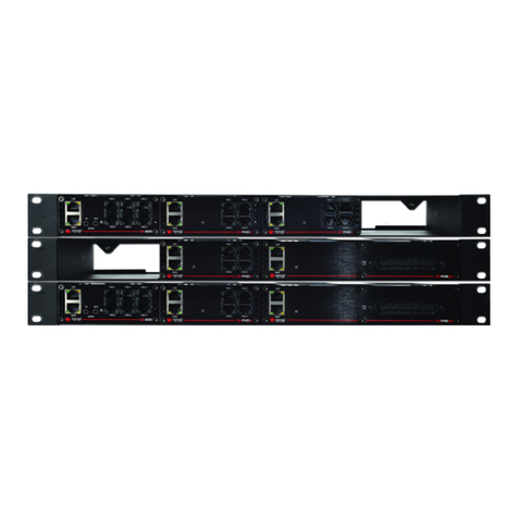
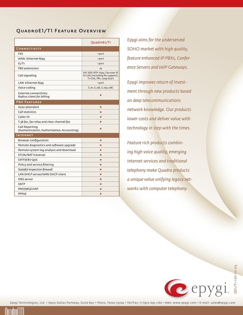
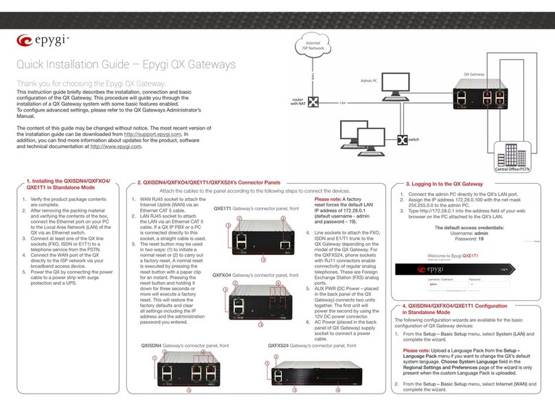
Epygi QXE1T1 User manual

Please Note: This document contains confidential and proprietary information owned by Epygi Technologies, LTD. Any copying, use or disclosure of
the document or the information contained herein without the written permission of Epygi Technologies, LTD. is strictly prohibited.
Copyright © 2003-2017 Epygi Technologies, LTD. All Rights Reserved.
Manual-I: Installation Guide for
QX Gateways
This manual is effective for all QX Gateways: QXE1T1, QXFXO4,
QXISDN4, and QXFXS24.

Manual-I: Installation Guide for QX Gateway
Revision 1.2 2
Notice to Users
This document, in whole or in part, may not be reproduced, translated or reduced to any machine-readable form without prior written approval.
Epygi provides no warranty with regard to this document or other information contained herein and hereby expressly disclaims any implied warranties of
merchantability or fitness for any particular purpose in regard to this document or such information. In no event shall Epygi be liable for any incidental,
consequential or special damages, whether based on tort, contract or otherwise, arising out of or in connection with this document or other information
contained herein or the use thereof.
Copyright and Trademarks
Copyright © 2003-2017 Epygi Technologies, LTD. All Rights Reserved. Quadro and QX are registered trademarks of Epygi Technologies, LTD. Microsoft,
Windows and the Windows logo are registered trademarks of Microsoft Corporation. All other trademarks and brand names are the property of their
respective proprietors.
Emergency 911 Calls
YOU EXPRESSLY ACKNOWLEDGE THAT EMERGENCY 911 CALLS MAY NOT FUNCTION WHEN USING QUADRO OR QX AND THAT EPYGI TECHNOLOGIES,
LTD. OR ANY AFFILIATES (AGENTS) SUBSIDIARIES, PARTNERS OR EMPLOYEES ARE NOT LIABLE FOR SUCH CALLS.
Limited Warranty
Epygi Technologies, LTD. (‘Epygi’) warrants to the original end-user purchaser every Quadro and QX to be free from physical defects in material and work-
manship under normal use for a period of one (1) year from the date of purchase (proof of purchase required) or two (2) years from the date of purchase
(proof of purchase required) for products purchased in the European Union (EU). If Epygi receives notice of such defects, Epygi will, at its discretion, ei-
ther repair or replace products that prove to be defective.
This warranty shall not apply to defects caused by (i) failure to follow Epygi’s installation, operation or maintenance instructions; (ii) external power
sources such as a power line, telephone line or connected equipment; (iii) products that have been serviced or modified by a party other than Epygi or an
authorized Epygi service center; (iv) products that have had their original manufacturer’s serial numbers altered, defaced or deleted; (v) damage due to
lightning, fire, flood or other acts of nature.
In no event shall Epygi’s liability exceed the price paid for the product from direct, indirect, special, incidental or consequential damages resulting from the
use of the product, its accompanying software or its documentation. Epygi offers no refunds for its products. Epygi makes no warranty or representation,
expressed, implied or statutory with respect to its products or the contents or use of this documentation and all accompanying software, and specifically
disclaims its quality, performance, merchantability or fitness for any particular purpose.
Return Policy
If the product proves to be defective during this warranty period, please contact the establishment where the unit was purchased. The Integrator will
provide guidance on how to return the unit in accordance with its established procedures. Epygi will provide the Return Merchandise Authorization Num-
ber to your retailer.
Please provide a copy of your original proof of purchase. Upon receiving the defective unit, Epygi, or its service center, will use commercially reasonable
efforts to ship the repaired or a replacement unit within ten business days after receipt of the returned product. Actual delivery times may vary depending
on customer location. The Distributor is responsible for shipping and handling charges when shipping to Epygi.
European Limited Warranty
The European Limited Warranty is the same as the Limited Warranty above, except the warranty period is for two years from the date of purchase.
Extended Warranty
Extended Warranty Option
Epygi offers an extended warranty program available for purchase by end users. This option is available at the time of purchase, extending the users origi-
nal warranty for an additional three (3) years. Combined with the original warranty, the extended warranty would offer a total of five (5) years protection
for European end users and four (4) years protection for non-European end users.
Extended Warranty Statement
Epygi Technologies, LTD. extends its Limited Warranty for an additional period of three (3) years from the date of the termination of the original Limited
Warranty period (proof of purchase required).
Epygi reserves the right to revise or update its products, pricing, software, or documentation without obligation to notify any individual or entity. Please
direct all inquiries to:
Epygi Technologies, LTD.
2233 Lee Road Suite 201 Winter Park, Florida 32789
Manual-I: Installation Guide for QX Gateway
Revision 1.2 3
Administrative Council for Terminal Attachments (ACTA) Customer Information
This equipment complies with Part 68 of the FCC rules and the requirements adopted by the ACTA. Located on the equipment is a label that contains,
among other information, the ACTA registration number and ringer equivalence number (REN). If requested, this information must be provided to the
telephone company.
The REN is used to determine the quantity of devices which may be connected to the telephone line. Excessive REN’s on the telephone line may result in
the devices not ringing in response to an incoming call. In most, but not all areas, the sum of the REN’s should not exceed five (5.0). To be certain of the
number of devices that may be connected to the line, as determined by the total REN’s contact the telephone company to determine the maximum REN for
the calling area.
This equipment cannot be used on the telephone company-provided coin service. Connection to Party Line Service is subject to State Tariffs.
If this equipment causes harm to the telephone network, the telephone company will notify you in advance that temporary discontinuance of service may
be required. If advance notice isn’t practical, the telephone company will notify the customer as soon as possible. Also, you will be advised of your right
the file a complaint with the FCC if you believe it is necessary.
The telephone company may make changes in its facilities, equipment, operations, or procedures that could affect the operation of the equipment. If this
happens, the telephone company will provide advance notice in order for you to make the necessary modifications in order to maintain uninterrupted
service.
If trouble is experienced with this equipment, please contact EPYGI TECHNOLOGIES, LTD.
If the trouble is causing harm to the telephone network, the telephone company may request you to remove the equipment from the network until the
problem is resolved.
Electrical Safety Advisory
To reduce the risk of damaging power surges, we recommend you install an AC surge arrestor in the AC outlet from which the Quadro or QX is powered.
Industry Canada Statement
This product meets the applicable Industry Canada technical specifications.
Safety Information
Before using the Quadro or QX, please review and ensure the following safety instructions are adhered to:
To prevent fire or shock hazard, do not expose your Quadro or QX to rain or moisture.
To avoid electrical shock, do not open the Quadro or QX. Refer servicing to qualified personnel only.
Never install wiring during a lightning storm.
Never install telephone jacks in wet locations unless the jack is specified for wet locations.
Never touch non-insulated telephone wire or terminals unless the telephone line has been disconnected at the network interface.
Use caution when installing or modifying cable or telephone lines.
Avoid using your Quadro or QX during an electrical storm.
Do not use your Quadro, QX or telephone to report a gas leak in the vicinity of the leak.
An electrical outlet should be as close as possible to the unit and easily accessible.
Emergency Services
The use of VoIP telephony is made available through IP networks such as the Internet and is dependent upon a constant source of electricity, network
availability and proper operation of the equipment. If a power outage, network disruption or equipment failure occurs, the VoIP telephony service could
be disabled. User understands that in any of those events the Quadro or QX may not be able to support 911 emergency services, and further, such services
may only be available via the user's regular telephone line or mobile lines that are not connected to the Quadro or QX. User further acknowledges that any
interruption in the supply or delivery of electricity, network availability or equipment failure is beyond Epygi's control and Epygi shall have no responsi-
bility for losses arising from such interruption.
Music on Hold Copyright
The default Music on Hold on the Quadro or QX is a 22 second fragment from Chopin's Nocturne Op.9 #2 performed by Marina Vardanyan and kindly pro-
vided to Epygi Technologies, LTD. The recording is royalty free.
Compliance with Laws
You may not use the Epygi Materials for any illegal purpose or in any manner that violates applicable domestic or foreign law. You are responsible for
compliance with all domestic and foreign laws governing Voice over Internet Protocol (VoIP) calls.

Manual-I: Installation Guide for QX Gateway
Revision 1.2 4
Document Edition History
Revision Date Description Valid for Models Valid for FW
1.0 27-May-16 Initial Release QX Gateways 6.1.17 and higher
1.1 24-Mar-17 Updated
QXFXO4, QXISDN4,
QXE1T1 6.1.17 and higher
QXFXS24 6.1.40 and higher
1.2 11-Dec-17 Updated
QXE1T1, QXFXO4,
QXISDN4 and
QXFXS24
6.2.1 and higher

Manual-I: Installation Guide for QX Gateway
Revision 1.2 5
Table of Contents
1 About Installation Guide ...............................................................................6
2 System Requirements ..................................................................................6
3 Hardware Overview......................................................................................7
3.1 The Panel of QX Gateways ....................................................................................... 7
3.2 QX Gateways Front Panel LEDs................................................................................ 9
4 Installing the QX Gateways ...........................................................................10
4.1 Networking Overview ................................................................................................ 10
4.2 Connecting the Hardware ......................................................................................... 13
5 QX Configuration (Stand-alone Mode) ...........................................................13
5.1 Logging in to QX Gateway ........................................................................................ 14
5.2 Basic Setup - System (LAN)...................................................................................... 15
5.3 Internet (WAN) .......................................................................................................... 17
6 IP Lines Configuration ..................................................................................21
6.1 Hosted PBX Survivability feature on QX .................................................................... 22
7 Configuring Extensions.................................................................................25
8 Configuring NAT Traversal............................................................................26
9 Changing Admin Password ..........................................................................27
10 Configuring QX Gateways with QX IP PBXs in Sharing Mode..........................29
10.1 Sharing Mode Configuration on the QX IP PBX......................................................... 29
10.2 Sharing Mode Configuration on the QX Gateway ...................................................... 30
11 Configuring QXFXS24 with QX IP PBXs.........................................................32
12 Registering on Epygi’s Support Portal ...........................................................33
13 Registering on Epygi’s SIP Server .................................................................35
14 Checking the Connections ...........................................................................37
15 Pin Assignment of RJ21 ...............................................................................39
16 Pin Assignment of E1/T1 ..............................................................................39
17 QXE1T1 PART 68 Certification......................................................................40
18 References ..................................................................................................41
19 Appendix: Software License Agreement........................................................42

Manual-I: Installation Guide for QX Gateway
Revision 1.2 6
1 About Installation Guide
This guide is intended for administrators who need to prepare for, install, configure and operate QX Gateways
(herein QX). In this guide, we describe the configuration of QXs as well as references to other guides, manuals
and complementary resources. After successfully configuring the QX, a user will be able to make SIP and PSTN
calls and access the Internet from devices connected to the Local Area Network (LAN).
This guide contains many example screen illustrations. Since QXs offer a wide variety of features and functional-
ity, the example screenshots shown may not appear exactly the same for your particular QX as they appear in
this manual. The example screenshots are for illustrative and explanatory purposes, and should not be con-
strued to represent your own unique environment.
2 System Requirements
One 100-240 VAC power outlet in close proximity to the QX.
One RJ45 Ethernet 10/100 broadband Internet connection.
For QXFXS24 at least one analog phone, RJ21 connector (F) with cable and distributed panel.
One CAT 5 Ethernet cable with RJ45 connector to connect to the QX LAN port.
One PC with a 10/100 Mbps Ethernet card.
TCP/IP network protocol installed on each PC.
Internet Explorer, Mozilla Firefox, Google Chrome or Opera browser is recommended.

Manual-I: Installation Guide for QX Gateway
Revision 1.2 7
3 Hardware Overview
QXFXO4 has 4 FXO ports, 1 Ethernet WAN and 1 Ethernet LAN ports.
QXISDN4 has 4 ISDN ports, 1 Ethernet WAN and 1 Ethernet LAN ports.
QXE1T1 has 1 E1T1 port, 1 Ethernet WAN and 1 Ethernet LAN ports.
QXFXS24 has 24 phone ports (FXS), 1 Ethernet WAN and 1 Ethernet LAN ports.
3.1 The Panel of QX Gateways
Below are presented the front and back panels:
1. WAN RJ45 socket to attach the Internet Uplink (WAN)
via an Ethernet CAT5 cable.
2. LAN RJ45 socket to attach the IP phone to the QX’s
LAN via an Ethernet CAT5 cable. Use a switch to con-
nect multiple IP phones.
3. The reset button may be used in two ways:
Pressing for an instant to initiate a normal restart.
Pressing and holding down for three seconds or more
to carry out a factory reset. This will clear all settings,
including the QX IP address and the changed admin
password, and restore the default configuration.
4. Line sockets to connect the QXFXO4 to the PSTN net-
work using standard analog phone service. These are
Foreign Exchange Office (FXO) analog ports. Figure 1: QXFXO4's Front Panel
Figure 3: QXISDN4's Front Panel
Figure 2: QXE1T1's Front Panel

Manual-I: Installation Guide for QX Gateway
Revision 1.2 8
5. Line sockets to connect QXISDN4 to the PSTN net-
work using ISDN service. These are Integrated Ser-
vices Digital Network (ISDN) trunks.
6. Line socket to connect QXE1T1 to the PSTN net-
work using E1T1 trunk.
7. RJ21 line socket to connect the FXS cables to ana-
log phones.
8. AUX PWR (DC Power) connector to connect two
units together. The first unit will power the second by
using 12V DC power connector.
9. AC Power supply socket to connect a power cable. Figure 4: QXFXO4/QXE1T1/QXISDN4's Back Panel
Figure 6: QXFXS24's Front Panel
Figure 5: QXFXS24's Back Panel

Manual-I: Installation Guide for QX Gateway
Revision 1.2 9
3.2 QX Gateways Front Panel LEDs
System Status LED Color State Description
Busy GREEN Blinking: normal activity
Info ORANGE
Blinking: an event occurred; details
specified in the System Event section
of the Management interface
Fault Red On: steady red, system unusable
Table 1: Front Panel LEDs
ETH Interface
Status LED Color State Description
WAN GREEN
On: link ok
Off: no link
Flickering: traffic on the link
LAN ORANGE On: full duplex mode
Off: half duplex mode
Table 2: Interface LEDs
LED indication during a firmware update or reboot
1. Power ON – steady GREEN LED for about 3 seconds.
2. Bootstrap loading – steady RED LED for about 3 seconds.
3. Steady ORANGE LED for about 15 seconds.
4. During Reboot – RED/GREEN LEDs are blinking.
5. After Reboot – Slow blinking GREEN LED (normal activity).
LED indication during emergency firmware update
1. Power ON – steady GREEN LED for about 3 seconds.
2. Bootstrap loading – steady RED LED for about 1 second.
3. Steady ORANGE LED for about 5 seconds.
4. RED LED blinking for about 1 second.
5. Steady ORANGE LED for about 1 minute.
6. Fast blinking ORANGE LED for about 5 second.
7. Reset the board and see the LED indication steps described for firmware update or reboot.
LED indication during emergency firmware update failure
1. Power ON – steady GREEN LED for about 3 seconds.
2. Bootstrap loading – steady RED LED for about 1 second.
3. Steady ORANGE LED for about 5 seconds.
4. RED LED blinking for about 1 second.
5. Steady ORANGE LED for about 1 minute.
6. Fast blinking RED LED for about 5 second.
7. Steady ORANGE LED for about 15 seconds.

Manual-I: Installation Guide for QX Gateway
Revision 1.2 10
4 Installing the QX Gateways
4.1 Networking Overview
To establish connections between the PSTN (or the legacy PBX) and the Internet, a gateway is needed. The QX
gateway, used as a stand-alone device, will perform the task of connecting the PSTN (or PBX) to a Private Data
Network or the Internet. The QX gateway will process and regulate the voice traffic between these networks
according to specified dial plan.
Figure 7: Stand-alone gateway (QXFXO4, QXE1T1 or QXISDN4): Connection overview
Figure 8: Stand-alone gateway (QXFXS24): Connection overview

Manual-I: Installation Guide for QX Gateway
Revision 1.2 11
Figure 9: Stand-alone gateway with Legacy PBX (QXFXS24): Connection overview
Every device within an IP network requires a unique IP address to identify itself. Since the QX gateway, used as
a stand-alone gateway, connects to both the LAN (Admin PC) and the WAN (Private Data Network or Internet),
it has to be part of both networks, and must have two IP addresses: one for the WAN side and one for the LAN
side. The QX gateway’s integrated firewall/NAT functionality will hide the LAN IP address from the WAN side.
There are two types of IP addresses:
Static – a fixed, manually assigned IP address that remains valid until changed. If you plan to use the QX
as your router, contact your Internet Service Provider (ISP) to find out if a static IP address is assigned to
your account. If so, you will need this static IP address when configuring the QX device.
Dynamic – a temporary address that is automatically assigned by your ISP and will change periodically. If
your ISP offers a dynamic IP address, the QX will act as a DHCP client and will receive a new IP address
from the ISP’s DHCP server or PPPoE feature.
Note: A DHCP client is a service that requests an IP address from a DHCP server. A DHCP server assigns on
request a unique IP address to a device. The QX, like many routers, acts as a DHCP client on its WAN interface
and as a DHCP server on its LAN interface.
Besides acting as a stand-alone device, QX gateways may serve as a PSTN LINE expansion for QX IP PBXs. In
this case, the QX gateway gets a WAN IP address from the DHCP server of the connected QX IP PBX.

Manual-I: Installation Guide for QX Gateway
Revision 1.2 12
Figure 10: QX gateway (QXFXO4, QXE1T1 or QXISDN4) in shared mode: Connection overview
Figure 11: QXFXS24 in shared mode: Connection overview

Manual-I: Installation Guide for QX Gateway
Revision 1.2 13
4.2 Connecting the Hardware
Verify the product package contents are complete. Refer to the contents sheet included in the packaging to
determine if all the items were shipped in the box.
1. Connect the Ethernet port on your PC via a straight CAT 5 cable with an RJ45 connector to the LAN
socket of the QX.
2. Connect PSTN Lines to FXO, E1T1 or ISDN interface ports on the QX.
3. Connect the LAN port on your PC via a straight CAT 5 cable with an RJ45 connector to the LAN socket
of the QX.
4. Connect the WAN port of the QX to the ISP network.
5. Connect the power cable to a power strip with surge protection and a UPS.
6. Power up any hub or switch followed by any PC and other devices on the LAN side.
7. Check the LEDs: The green WAN LED will blink when cables are connected to these ports and all de-
vices are powered up. If the green WAN LED does not blink, verify cabling and ensure that all devices
are powered up.
Note: CAT 5 cables can be faulty without any visual indication. The LAN and WAN LEDs verify that the Ethernet
connection is established between the end points. If these LEDs are not illuminated, there is a connection prob-
lem between the QX and the other device.
5 QX Configuration (Stand-alone Mode)
Verify functionality of both IP and PSTN calls:
PSTN telephony: If the QX is connected to the PSTN network via the E1/T1, FXO or ISDN interface, verify
the functionality of PSTN calls:
Make an outbound PSTN call by dialing PSTN number.
Arrange to receive an incoming call. The incoming PSTN calls will be routed to the Auto Attendant by
default.
Bandwidth – to regulate the number of calls allowed by the QX to avoid degradation in low bandwidth
conditions.
Time/Date – to ensure the correct time and time zone are used for call records.
Regional Settings – if your QX is located outside the United States, it is important to properly configure
your line connections to the PSTN in your location.

Manual-I: Installation Guide for QX Gateway
Revision 1.2 14
5.1 Logging in to QX Gateway
1. Start a browser (Google Chrome, Opera, Mozilla Firefox, etc.) on a PC connected to the QX.
2. Since Firewall is disabled on the QX by default, you may connect the Web GUI either from WAN or LAN
side of the QX. To connect the QX’s Web GUI from the WAN side, enter http://xxx.xxx.xxx.xxx (IP ad-
dress assigned by the company’s DHCP server) in the address field of your browser. If the PC is con-
nected to the QX’s LAN side, enter the 172.28.0.1 address in the address field of your browser.
3. The Login page of the QX will be displayed.
Figure 12: Login page
4. Enter the default credentials (Username: admin and Password: 19) to log into the QX WEB GUI as an
administrator. Note: If you consecutively enter a wrong password and/or username for five times the de-
vice will be unavailable for login for five minutes.
Figure 13: Dashboard page

Manual-I: Installation Guide for QX Gateway
Revision 1.2 15
5.2 Basic Setup - System (LAN)
Navigate to the SetupBasic SetupSystem (LAN). The System Configuration Wizard defines the QX's LAN set-
tings and specifies regional configuration. The System Configuration Wizard must be run upon QX first startup.
Some sections in this wizard may be skipped and left default for the basic configuration.
Note:It is strongly recommended to leave the factory default settings unchanged if their meanings are not
completely understandable to the party administrating the QX.
System Configuration
Enter the unique name into the Hostname field and the LAN side domain name (to which the QX belongs to)
into the Domain Name text field. The LAN IP Address doesn’t need to be changed for a basic configuration. For
more advanced configuration, record a new LAN IP Address and keep it handy, you will need it for subsequent
access to the QX’s WEB GUI.
Figure 14: System Configuration section
DHCP Settings for the LAN Interface
Enabled DHCP server allows the QX automatically assign dynamic IP addresses to the devices on its LAN side.
If you haven't changed the default LAN IP address of the QX, you also may leave the default values for the IP
Address Range. TIP: Make sure your connected LAN devices belong to the same network as the LAN port of
your QX. Make sure there is only one DHCP server on the LAN, otherwise, unpredictable network behavior can
occur.

Manual-I: Installation Guide for QX Gateway
Revision 1.2 16
Figure 15: DHCP Settings for the LAN Interface section
Regional Settings and Preferences
If your QX is located outside of the United States, it is important to properly configure your line connections to
the PSTN in your location.
Figure 16: Regional Settings and Preferences section
Proper configuration of the Regional Settings is important for the functionality of the voice subsystem. The Re-
gional Settings determine the proper telephony parameters on the Line/Trunk and Phone ports of the QX for the
specified country. Select the country where the QX is located. If you do not find your country in the list, pick the
closest in your timezone. The QX obtains the correct time automatically over the Internet from a time server. If
you are not located in the US/Central standard time zone, you will need to change the Timezone to your region.

Manual-I: Installation Guide for QX Gateway
Revision 1.2 17
Summary Page
Finish the wizard and click "OK" to apply the changes made in any section of the wizard. You must con-
firm the settings within 20 minutes. Otherwise the device will return back to the previous configuration
and reboot.
If you do not use DHCP for your LAN and you have changed your LAN settings, make sure that the IP
address of the PC connected to QX is still within the specified IP address range, otherwise your PC may
not establish a connection to QX.
If you changed the network configuration of the LAN, restart your LAN connection to receive a new IP
address from the new network. Then you can access the Web Management of the QX on the new IP
address you’ve assigned to the QX.
5.3 Internet (WAN)
Go to the SetupBasic SetupInternet (WAN) to configure the network parameters for the WAN interface and
adjust QX’s connectivity to an external network. The Internet Configuration Wizard defines WAN settings and
adjusts QX's connectivity to the global network. It must be run if QX is desired to be connected to the Internet.
Before configuring the WAN port to the Internet, you need to get the following information from your internet
service provider:
Bandwidth – the available upstream and downstream.
WAN IP Configuration – is DHCP supported? If yes, no more information is needed. If DHCP is not sup-
ported, the following data is needed: the WAN IP address, the subnet mask, the IP address of the de-
fault gateway and the IP address of the Domain Name Server (DNS).
MAC address – needed when the ISP requires a specific MAC address for the WAN.
Additionally, for Point-to-Point Protocol over Ethernet (PPPoE) WAN interface, you need to get the following in-
formation from your internet service provider:
PPP Configuration – does your ISP use a dynamic or fixed WAN IP address? If the WAN IP address is
dynamic, no more information is needed. If the WAN IP address is fixed, you will have to enter it.
Authentication – does your ISP require authentication? If authentication is required, information about
the corresponding method (PAP, CHAP or MSCHAP) is needed including the username and password
of the PPPoE account.
This information will be needed to be inserted in the Internet Configuration Wizard.
Uplink Configuration
Select the desired WAN Interface Protocol and enter the WAN Interface Bandwidth to assure the quality of IP
calls.
If the available bandwidth is used to the point where the quality of an additional IP call would suffer, then new IP
calls are rejected. The bandwidth provided by your ISP must be specified for both Upstream and Downstream
fields. The default entry in both fields is 100000, the maximum bandwidth of the 100 Mb uplink module. For
basic DSL and cable modem service in the United States, typical values are 300 for Upstream and 1500 for
Downstream. The Min Data Rate text field is used to specify the amount of bandwidth reserved for data appli-
cations. The value entered here needs to be smaller than the value specified for Upstream Bandwidth.
Select the WAN Interface Protocol by choosing between available WAN interface protocols: PPPoE (Point to
Point over Ethernet), PPTP (Point to Point Tunneling Protocol), Ethernet and VLAN.
Based on this selection the wizard's configuration pages may differ.

Manual-I: Installation Guide for QX Gateway
Revision 1.2 18
Figure 17: Uplink Configuration section
PPPoE
Keep Connection Alive – keeps the connection alive by sending control packets for the link state verifica-
tion.
Authentication Settings – insert the authentication parameters (Username and Password) to register on
the ISP server.
Dial Behavior – select the Dial Behavior type.
Dial manually – if selected, a button will be displayed in the top WEB management window to switch
the connection on/off.
Always connected – if selected, the QX will always stay connected.
IP Address Assignment – select the IP Address assignment type for the PPPoE interface:
Obtain an IP Address automatically – with this option QX will get an IP address dynamically.
Use the following IP Address – set the IP address manually.
PPTP
Obtain an IP Address automatically – with this option selected, QX will use DHCP to get an available IP
address from your local network or ISP.
Use the following IP Address – if selected, manually provide the settings for the WAN interface.
Click Next to continue the configuration of the PPP/ PPTP settings:
PPTP Server – enter the IP address of the PPTP server.
Encryption – select the encryption for the traffic over the PPTP interface.
Keep Connection Alive – keeps the connection alive by sending control packets for the link state verifica-
tion.
Authentication Settings – insert the authentication parameters (Username and Password) to register on
the ISP server.
Dial Behavior – select the Dial Behavior type.
Dial manually – if selected, a button will be displayed in the top WEB management window to switch
the connection on/off.
Always connected – if selected, the QX will always stay connected.

Manual-I: Installation Guide for QX Gateway
Revision 1.2 19
IP Address Assignment – select the IP Address assignment type for the PPPoE interface:
Obtain an IP Address automatically – with this option QX will get an IP address dynamically.
Use the following IP Address – set the IP address manually.
Ethernet
Obtain an IP Address automatically – with this option selected, QX will use DHCP to get an available IP
address from your local network or ISP.
Use the following IP Address – if selected, manually provide the settings for the WAN interface.
VLAN
VLAN ID – select VLAN ID from the configured VLAN list.
Click Next to continue the configuration of the VLAN IP Configuration settings.
Obtain an IP Address automatically – with this option selected, QX will use DHCP to get an available IP
address from your local network or ISP.
Use the following IP Address – if selected, manually provide the settings for the VLAN interface.
WAN Interface Configuration
If your ISP requires a specific MAC address (e.g. for authentication purposes), it can be entered on this page.
The required MAC address can be entered into the User-defined field. If a specific MAC address is not required,
leave the default selection This device selected.
Figure 18: WAN Interface Configuration section
Use the MTU drop-down list to select the maximum size of packet that can be sent in a packet or frame-based
network such as the Internet. QX supports packet fragmentation. TIP: The default MTU size is 1500 Bytes for
Ethernet protocol and 1400 Bytes for PPPoE.

Manual-I: Installation Guide for QX Gateway
Revision 1.2 20
DNS Settings
Figure 19: DNS Settings section
Obtain DNS Server Address automatically – automatically configures the assignment of the name server
address from the provider party.
Use the following DNS Server Address – is used to manually assign a name server as follows:
Preferred DNS – insert the IP address of an external name server.
Alternate DNS – insert the IP address of the secondary name server that will be used if the main name
server cannot be accessed.
Summary Page
Finish the wizard and click "OK" to apply the changes made in any section of the wizard. You must con-
firm the settings within 20 minutes. Otherwise the device will return back to the previous configuration
and reboot.
It is strongly recommended to not change the factory default settings if their meanings are not fully clear
to you.
This manual suits for next models
3
Table of contents
Other Epygi Gateway manuals

Epygi
Epygi QUADRO FXO User manual

Epygi
Epygi QXISDN4 User manual

Epygi
Epygi QuadroFXO Service manual

Epygi
Epygi QX series Manual

Epygi
Epygi QUADROISDN User manual

Epygi
Epygi QUADRO FXO User manual

Epygi
Epygi Quadro Series User manual

Epygi
Epygi Quadro ISDN User manual

Epygi
Epygi QUADRO T1 Service manual

Epygi
Epygi QuadroE1/T1 Service manual