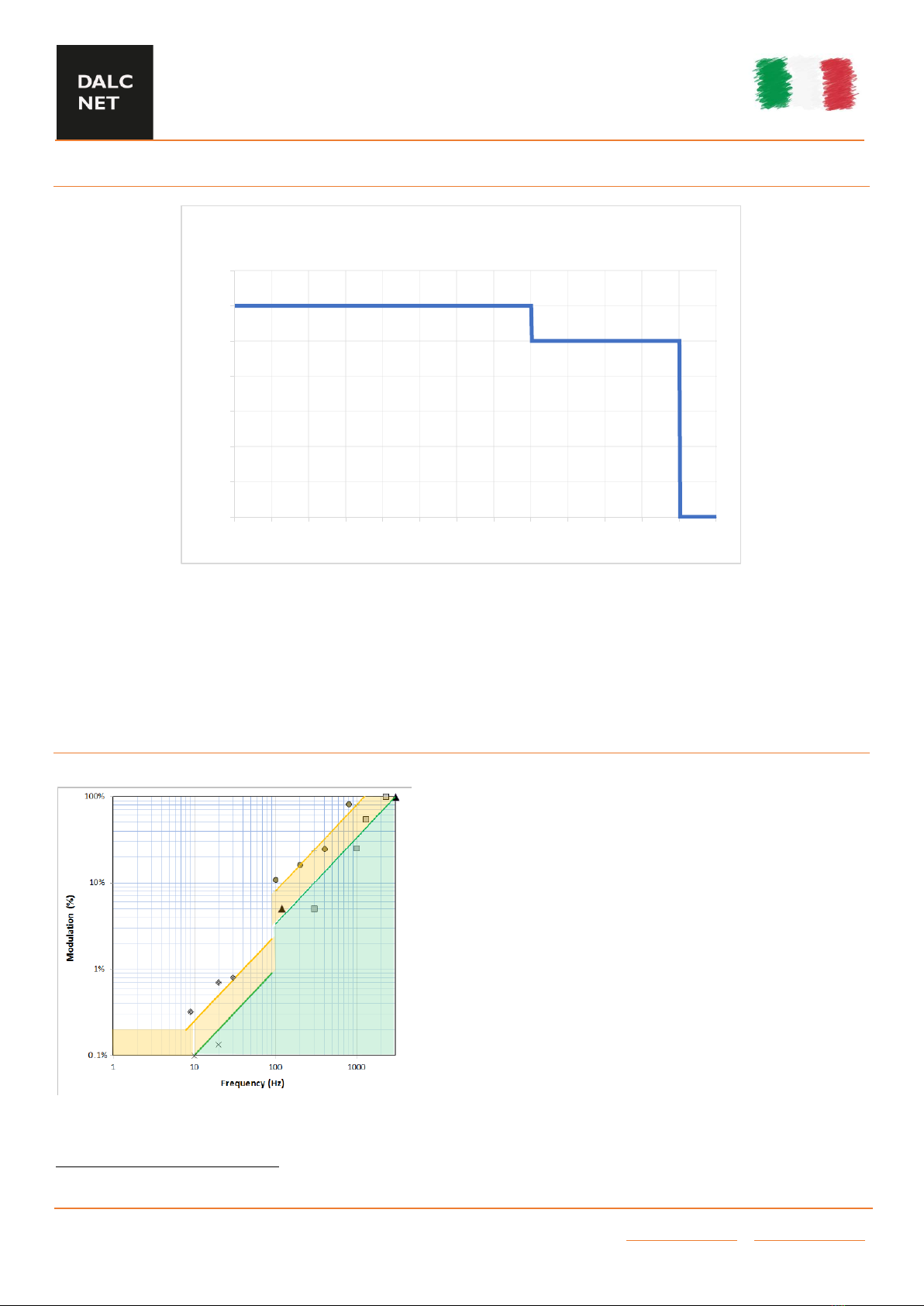
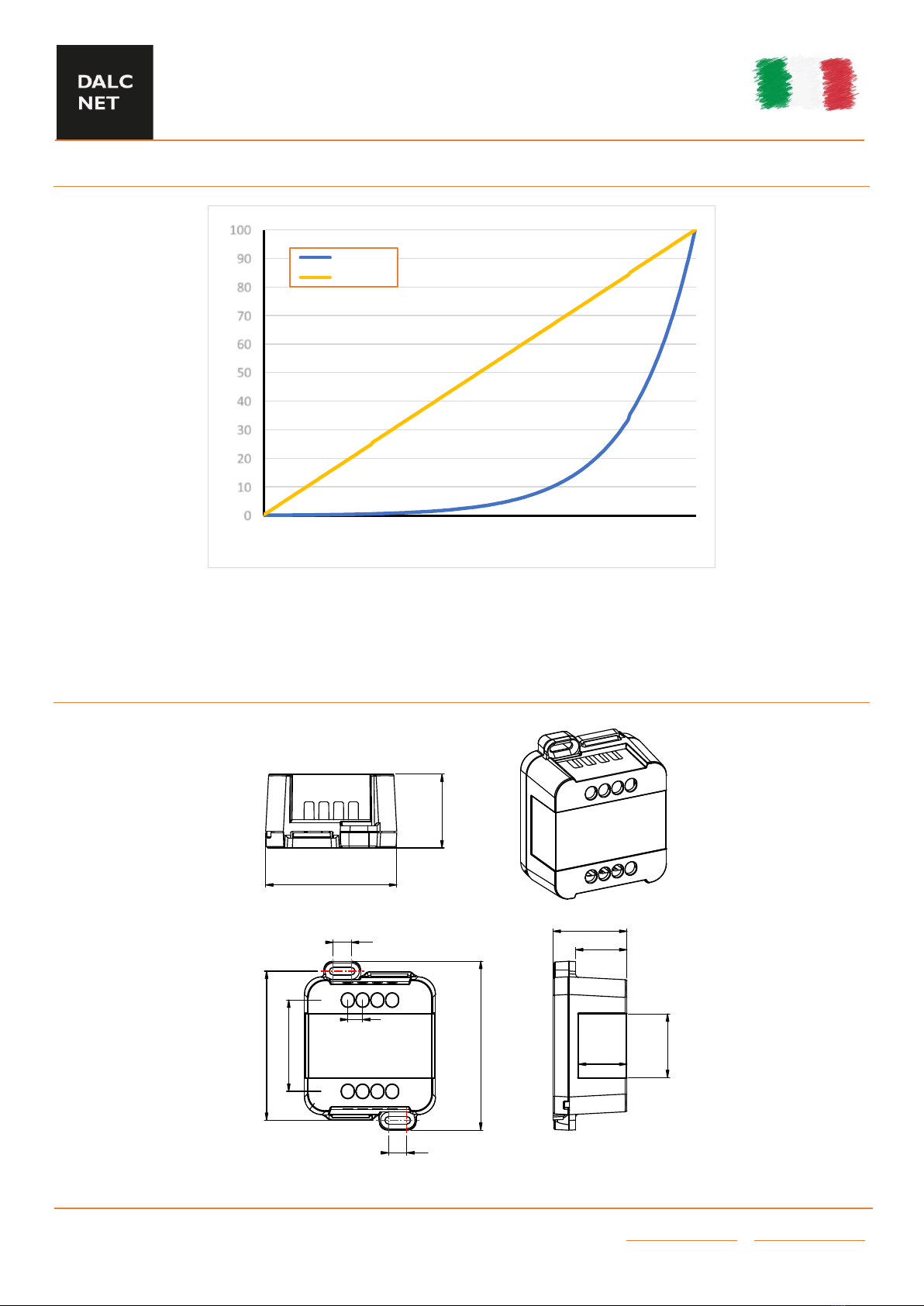
DALCNET MINI 1CV CASAMBI Application guide

MINI 1CV CASAMBI
PRELIMINARY
Device Manual
Made in Italy
DALCNET S.r.l.
36077 Altavilla Vicentina (VI) –Italy
Via Lago di Garda, 22
Tel. +39 0444 1836680
www.dalcnet.com –info@dalcnet.com
Rev. 09/08/2022 - Pag. 1/8
FEATURES
CASAMBI LED DIMMER
Power Supply: 12-24-48 Vdc
Voltage output for LED strip and LED module
Control of the White and Monochromatic Light
BLE Command: APP CASAMBI
Local Command: n°1 Normal Open Push Button
Control voltage outputs for R
Adjusting the brightness up to completed off (Dim to Dark)
Minimum Brightness level: up to 0,1%
PWM Modulation
Adjusting PWM frequency: 600 / 4000 Hz
Adjusting output curve: Linear / Logarithmic
Soft start and soft stop
Soft Dimming regulation
Extended temperature range
100% Functional test
PRODUCT DESCRIPTION
MINI-1CV-CASAMBI is a single channel LED dimmer, controllable via Bluetooth using the Casambi APP or locally with a normally
open push button.
The LED dimmer is suitable for driving Strip LED and LED modules, White and monochromatic constant voltage loads. It is possible
connect a power supply at 12-24-48 Vdc.
The maximum total output current is 12A. The LED dimmer has over voltage protection, under voltage protection, reverse polarity
protection and input fuse protection.
By means of the CASAMBI APP, the MINI-1CV-CASAMBI allows you to make a variety of effects: from simple brightness
adjustments to more complex lighting control system, thanks to the creation of multiple scenarios, animations, timers, daylight
control etc.
CASAMBI APP can be downloaded for free on Apple App Store and Google Play Store.
⇢For the up-to-date manual, please visit our website: www.dalcnet.com or scan the QR Code located on the product’s
label.
⇢For the correct functioning of the CASAMBI APP, please visit the forum on the Casambi website:
https://support.casambi.com/support/home

MINI 1CV CASAMBI
PRELIMINARY
Device Manual
Made in Italy
DALCNET S.r.l.
36077 Altavilla Vicentina (VI) –Italy
Via Lago di Garda, 22
Tel. +39 0444 1836680
www.dalcnet.com –info@dalcnet.com
Rev. 09/08/2022 - Pag. 2/8
PRODUCT CODE
CODE
POWER SUPPLY
OUTPUT LED
N° OF CHANNEL
TYPE OF
COMMAND
MINI-1CV-CASAMBI
12-24-48 VDC
1 x 12A
1
APP CASAMBI
N°1 N.O. PUSH BUTTON
PROTECTIONS
OVP
Over voltage protection1
✔
UVP
Under voltage protection1
✔
RVP
Reverse polarity protection1
✔
IFP
Input fuse protection1
✔
TYPE OF PROFILE
NAME OF PROFILE
# PROFILE
DESCRIPTION
MINI 4kHz (Lin)
9531
One channel PWM dimmer
Output PWM Frequency = 4000Hz
Linear dimming curve
PWM resolution 1000step
MINI 4kHz (Log)
23372
One channel PWM dimmer
Output PWM Frequency = 4000Hz
Logarithmic dimming curve
PWM resolution 1000step
MINI 600Hz (Lin)
24661
One channel PWM dimmer
Output PWM Frequency = 600Hz
Linear dimming curve
PWM resolution 1666step
MINI 600Hz (Log)
22989
One channel PWM dimmer
Output PWM Frequency = 600Hz
Logarithmic dimming curve
PWM resolution 1666step
1
The protections refer to the logical control circuit.

MINI 1CV CASAMBI
PRELIMINARY
Device Manual
Made in Italy
DALCNET S.r.l.
36077 Altavilla Vicentina (VI) –Italy
Via Lago di Garda, 22
Tel. +39 0444 1836680
www.dalcnet.com –info@dalcnet.com
Rev. 09/08/2022 - Pag. 3/8
REFERENCE STANDARDS
EN 55015
Limits and methods of measurement of radio disturbance characteristics of electrical lighting and similar
equipment
EN 61547
Equipment for general lighting purposes –EMC immunity requirement
EN 61347-1
Lamp Controlgear –Part 1: General and safety requirement
EN 61347-2-13
Lamp Controlgear –Part 2-13: Particular requirement for d.c. or a.c. supplied electronic Controlgear for
LED modules
TECHNICAL SPECIFICATION
MINI 1 CV CASAMBI
Supply voltage
Min: 10,8Vdc –Max: 52,8Vdc
Output voltage
=Vin
Input current
Max 12A
Output current2
max 12A @40°C –max 10A @60°C
Nominal Power
12 Vdc
144W @12A –120W @10A
24 Vdc
288W @12A –240W @10A
48 Vdc
576W @12A –480W @10A
Power loss in standby mode
< 0,5W
Type of load
R3
Dimming curve
Logarithmic or Linear
Dimming Range4
0,1 –100%
Minimum dimming level
0,1% (Logarithmic curve 600Hz)5
0,4% (Linear curve 600Hz)
0,5% (Logarithmic curve 4kHz)
0,5% (Linear curve 4kHz)
Dimming method
Pulse Width Modulation “PWM”
PWM Frequency4
600 –4000 Hz
PWM Resolution4
1666 Step (600Hz)
1000 Step (4kHz)
Operating frequencies4
2402 –2483 MHz
Maximum output power4
7dBm
Storage temperature
Min: -40°C –Max: 60°C
Ambient temperature, Ta range2
Min: -10°C –Max: 60°C
Connector type
Screw terminals
Wiring
Solid Size
0,05 ÷ 2,5 mm2/ 30 ÷ 12 AWG
Stranded size
Wire strip length
6,5 mm
IP protection grade
IP20
Casing material
Plastic
Packaging unit (pieces/unit)
1pz
Mechanical dimension
44 x 57 x 25 mm
Packaging dimension
56 x 68 x 35 mm
Weight
44g
2
For the complete range, see the Operating Window of the product
3
Type of load: Resistive and DC/DC Converter
4
The parameters are derived from the configuration of the Casambi module.
5
Dim to Dark Dimming

MINI 1CV CASAMBI
PRELIMINARY
Device Manual
Made in Italy
DALCNET S.r.l.
36077 Altavilla Vicentina (VI) –Italy
Via Lago di Garda, 22
Tel. +39 0444 1836680
www.dalcnet.com –info@dalcnet.com
Rev. 09/08/2022 - Pag. 4/8
WIRING DIAGRAM
As show in the wiring diagram carry out the following steps for the installation of the product
Connect the positive of the LED load to the “LED” terminals with the symbol “+”, and the negative of the LED load to the
“LED” terminals with the symbol “-“.
Connect the N.O. push button to the INPUT terminals with the “ ” symbol.
Be sure not to connect live parts to the PUSH N.O.
Connect a 12-24-48 Vdc constant voltage SELV power supply (depending on LED load plate data) to the DC IN terminal
with the symbols “+” and “-”.
Be sure not to use constant current LED Driver and check that the polarity of the cables is correct.
Like any other Bluetooth enable product, make sure you don’t place the product inside a metal case or next to large metal
structures. The metal will greatly block the radio signal important for the correct operation of the device.

MINI 1CV CASAMBI
PRELIMINARY
Device Manual
Made in Italy
DALCNET S.r.l.
36077 Altavilla Vicentina (VI) –Italy
Via Lago di Garda, 22
Tel. +39 0444 1836680
www.dalcnet.com –info@dalcnet.com
Rev. 09/08/2022 - Pag. 5/8
LOCAL COMMANDS FUNCTIONALITY
N.O. PUSH BUTTON
6
N° Push Button
Functions
1
Controls a luminaire
Click
Long press (>1s)
Tap to turn a luminaire on or off –
hold to adjust luminaire brightness
Controls an element
Click
Long press (>1s)
Tap to turn a device element on or off
–hold to adjust the element value
Control a group
Click
Long press (>1s)
Tap to turn a group on or off –hold
to adjust brightness
Control scene
Click
Long press (>1s)
Tap to turn a scene on or off –hold
to adjust scene brightness
Control all luminaires
Click
Long press (>1s)
Tap to turn all luminaires on or off –
hold to adjust brightness
Cycles scenes
Click
Long press (>1s)
Tap to cycle through the list of
scenes –hold to adjust current
scene brightness
Active/Standby
Click
Long press (>1s)
Tap to switch between two scenes –
hold to adjust current scene
brightness
For all other functions, please refer to the CASAMBI APP document at:
https://support.casambi.com/support/home
UNPAIR DEVICE FROM THE CASAMBI NETWORK
If the device is associated with a network to which you do not have the credentials and you want to associate it with a new one,
follow the settings specified in the Casambi APP in the "Nearby Devices" section. Once you have selected the unpair function and
started the procedure, turn off the main power of the power supply connected to the MINI-1CV-CASAMBI and turn it on again after
1 - 2 seconds.
If the main power supply is switched off and on again quickly, unpair may not be done properly. Repeat the unpair sequence by
allowing 1 or 2 more seconds to elapse between the moment you turn off and re-turn on the main power of the power supply
7
.
In case it is difficult to unpair, it is possible to associate a button N.O. to the input "INPUT" of the MINI-1CV-CASAMBI and press
it during the unpair procedure.
POSITIONING Tc POINT
Bottom side, under the LED output connector.
6
By default, the N.O. Push button is set as “Control a luminaire” and controls the output of the MINI-1CV-CASAMBI.
7
The discharge time of the power supply secondary depends on the construction characteristics of the power supply used.

MINI 1CV CASAMBI
PRELIMINARY
Device Manual
Made in Italy
DALCNET S.r.l.
36077 Altavilla Vicentina (VI) –Italy
Via Lago di Garda, 22
Tel. +39 0444 1836680
www.dalcnet.com –info@dalcnet.com
Rev. 09/08/2022 - Pag. 6/8
OPERATING WINDOW
Operating ambient temperature (Ta) range: -10°C ÷ +40°C ⇢output current up to 12A
-10°C ÷ +60°C ⇢output current up to 10A
FLICKER PERFORMANCE
Thanks to the 4khz dimming frequency the MINI-1CV-CASAMBI allows
to reduce the Flicker phenomenon.
Depending on the sensitivity of a person and the type of activity,
flickering can affect a person’s well-being even if the luminance
fluctuations are above the threshold that can be perceived by the
human eye.
The graph shows the phenomenon of Flickering in function at the
frequency, measured throughout the dimming range.
The results show the low-risk zone (yellow) and the no-effect zone
(green). Defined by IEEE 1789-2015
8
8
Institute of Electrical and Electronics Engineers (IEEE). IEEE std 1789: Recommended Practices for Modulating Current in High-
Brightness LEDs for Mitigating Health Risks to Viewers.
0
2
4
6
8
10
12
14
0 5 10 15 20 25 30 35 40 45 50 55 60 65
I LED [A]
TA [°C]
OPERATI N WINDOWS

MINI 1CV CASAMBI
PRELIMINARY
Device Manual
Made in Italy
DALCNET S.r.l.
36077 Altavilla Vicentina (VI) –Italy
Via Lago di Garda, 22
Tel. +39 0444 1836680
www.dalcnet.com –info@dalcnet.com
Rev. 09/08/2022 - Pag. 7/8
DIMMING CURVE
MECHANICAL DIMENSION
0
10
20
30
40
50
60
70
80
90
100
010 20 30 40 50 60 70 80 90 100
Output power [%]
Dimming Level [%]
Logarithmic
Linear

MINI 1CV CASAMBI
PRELIMINARY
Device Manual
Made in Italy
DALCNET S.r.l.
36077 Altavilla Vicentina (VI) –Italy
Via Lago di Garda, 22
Tel. +39 0444 1836680
www.dalcnet.com –info@dalcnet.com
Rev. 09/08/2022 - Pag. 8/8
TECHNICAL NOTE
INSTALLATION
•CAUTION: The product may only be connected and installed by a qualified electrician. All applicable regulations, legislation, and
building codes must be observed. Incorrect installation of the product can cause irreparable damage to the product and the
connected LEDs.
•Maintenance must be performed only by a qualified electrician in compliance with current regulations.
Pay attention when connecting the LEDs: polarity reversal results in no light output and often damages the LEDs.
•The product is designed and intended to operate LED loads only. Powering non-LED loads may push the product outside its
specified design limits and is, therefore, not covered by any warranty.
Operating conditions of the product may never exceed the specifications as per the product datasheet.
•The product must be installed inside a switchgear/controlgear cabinet and/or junction box protection against overvoltage.
•The product must be installed in a vertical or horizontal position with the label/top cover facing upwards or vertically. Other
positions are not permitted. The bottom position is not permitted (label/top cover facing down).
•Keep separated 230Vac (LV) circuits and not SELV circuit from safety extra low voltage (SELV) circuit and from any connection
with this product. It is absolutely forbitten to connect, for any reason whatsoever, directly or indirectly, the 230Vac mains voltage
to the product (terminal block of BUS included).
•The product must be dissipated correctly.
•The use of the product in harsh environments could limit the output power.
•For built-in components inside luminaires, the ta ambient temperature range is a guideline given for the optimum operating
environment. However, integrator must always ensure proper thermal management (i.e. correct mounting of the device, air flow
etc.) so that the tc point temperature does not exceed the tc maximum limit in any circumstance. Reliable operation and lifetime
is only guaranteed if the maximum tc point temperature is not exceeded under the conditions of use.
POWER SUPPLY
•Only use SELV power supplies with limited current for device power supply, short circuit protection and the power must be
dimensioned correctly.
In the case of power supplies equipped with ground terminals, it is mandatory to connect ALL protective ground points (PE=
Protection Earth) to a properly and certified protection earth.
•The connection cables between the very low voltage power source and the product must be properly dimensioned and must be
insulated from any wiring or part at non-SELV voltage. Use double insulated cables.
•Dimension the power of the power supply in relation to the load connected to the device. In case the power supply is oversized
compared to the maximum absorbed current, insert a protection against over-current between the power supply and the device.
COMMAND
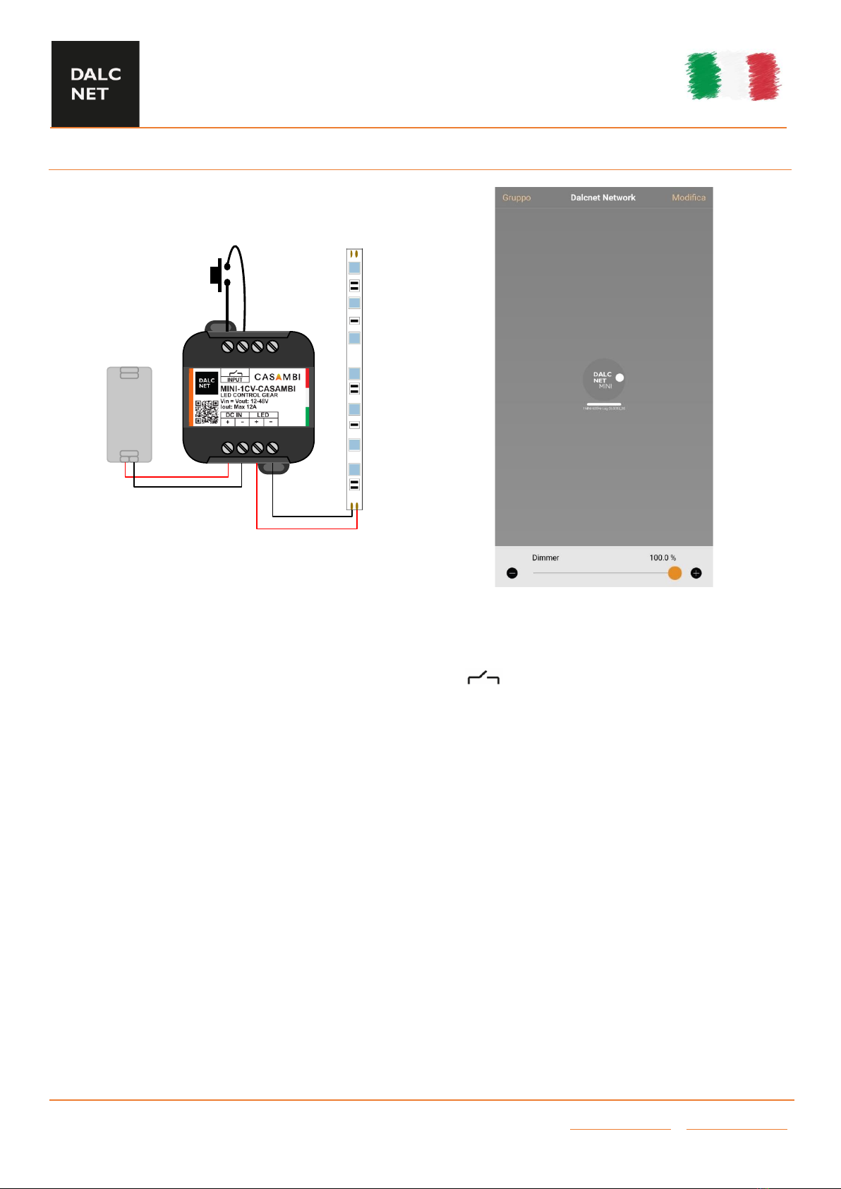
•The length of the cables connecting between the local commands (N.O. Push button, 0-10V, 1-10V, Potentiometer or other) and
the product must be less than 10m. The cables must be properly dimensioned and must be insulated from any non-SELV wiring
or voltage. It is recommended to use double insulated cables, if deemed appropriate also shielded.
•ALL device and control signal connected to the local command “N.O. Push button” with symbol, they must not supply any
type of voltage.
•ALL device and control signal connect to the local command (0-10V, 1-10V, potentiometer or other) must be SELV type (the
device connected must be SELV or supply SELV signal).
OUTPUTS
•It is recommended a length of the connecting cables between the product and the LED module less than 10m. The cables must
be properly dimensioned and must be insulated from any wiring or circuits at voltage not SELV. It is recommended to use double
insulated cables. In case you want to use connecting cables between the product and the LED module greater than 10m, the
installer must guarantee the correct operation of the system. In any case, the connection between the product and the LED
module must not exceed 30m.
ONLY CASAMBI/BLUETTOTH PRODUCT
•WARNING: For optimal functionality of the Casambi signal, do not put the device into metal or aluminium boxes and do not shield
the device. As any other Casambi product, should not be placed in a metal enclosure or next to large metal structures. Metal will
effectively block all radio signals which are crucial to the operation of the product.
WARNINGS
•To guarantee the best performances and the full use of functions, make sure to download on your device the last release of
CASAMBI APP.
•Whenever CASAMBI APP requires an upgrade of the profile installed in the LED Dimmers, follow the instruction to do it. This allows
you to stay always up to date and benefit of new functions released.
•Functionality test are done on all dimmers to ensure the right working. In case the device is still paired to “Dalcnet network”, you
are asked to unpair it by following the instructions on CASAMBI APP and in paragraph “UNPAIR DEVICE FROM THE CASAMBI
NETWORK”.
This manual suits for next models
1
Table of contents