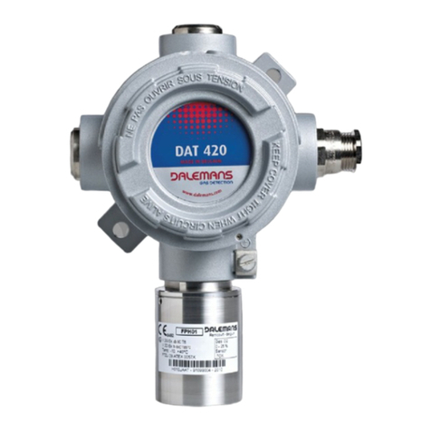
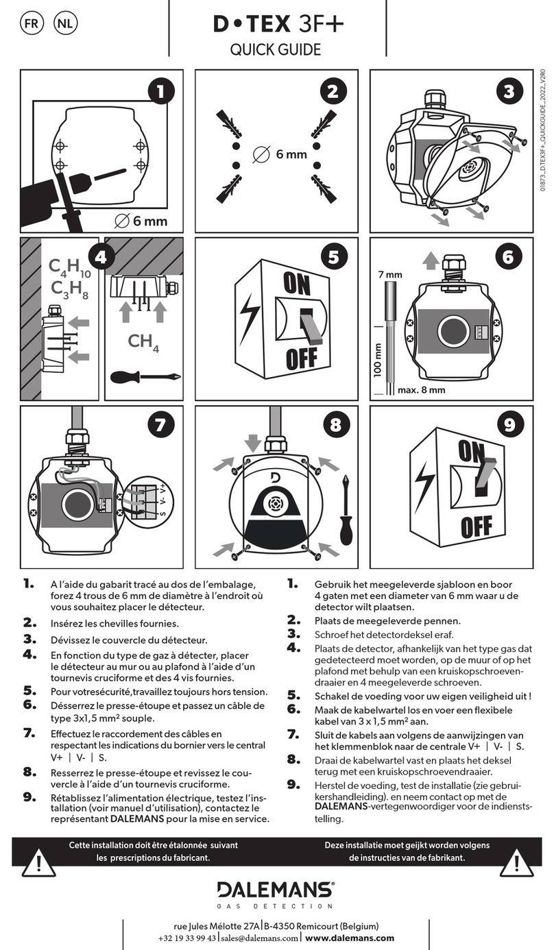
DALEMANS D-TEX3F+ User manual


Copyright ©2018 par DALEMANS s.a.
Revision V1R0 • 05/2018
Any reproduction, partial or full, of this document by means of
any process whatsoever without prior written consent from
DALEMANS s.a. is strictly prohibited.
Warning
All information contained in this document is non-contractual
and subject to change without notice.
We also encourage you to regularly check the availability
of a new version on our website: http://www.dalemans.com
Please contact your distributor in case of doubt.
Dalemans s.a.
Rue Jules Mélotte, 27 • B-4350 Remicourt (Belgium)
Tel. +32(0)19 33 99 43 • Fax +32(0)19 33 99 44
Email: sales@dalemans.com

www.dalemans.com
|
3
CONTENTS
WARNINGS..................................................................................................................4
LIMITATIONS...............................................................................................................4
SAFETY INSTRUCTIONS............................................................................................5
DIRECTIVE 2014/34/EU (ATEX)..................................................................................6
LIMIT OF LIABILITY ....................................................................................................7
ENVIRONMENT ...........................................................................................................7
QUALITY ASSURANCE ..............................................................................................7
1. INTRODUCTION...................................................................................................8
1.1. Certification .................................................................................................8
2. DESCRIPTION......................................................................................................9
2.1. Overview .....................................................................................................9
2.2. Dimensions................................................................................................10
3. INSTALLATION..................................................................................................11
3.1. Positioning of the detectors.......................................................................11
3.2. Assembly...................................................................................................12
3.3. Wiring........................................................................................................13
3.4. Electrical connection .................................................................................13
4. MAINTENANCE..................................................................................................14
4.1. Replacing the sensor ................................................................................14
4.2. Error diagnosis..........................................................................................15
4.3. Spare parts and accessories.....................................................................15
5. SPECIFICATIONS..............................................................................................16

www.dalemans.com
|
4
WARNINGS
BEFORE the installation, maintenance or repair of the detector, check that there
is no explosive gas or explosive vapour in the atmosphere. Never open the
detector when an explosion risk is present. To reduce the risk of electrostatic
discharge, always use a damp cloth to clean the detector.
The INSTALLATION, COMMISSIONNING and MAINTENANCE must be performed
exclusively by DALEMANS or by an approved service centre and in all cases by
qualified personnel having received appropriate training. The gas detection
equipment must be calibrated at least once a year to compensate for any loss of
sensitivity of the sensors.
▪The guarantee offered by DALEMANS will be void if this equipment is not installed, used and
maintained in strict compliance with these instructions, warnings and limits of use.
▪By following these instructions, you guarantee the proper functioning of the equipment. Please
contact DALEMANS for any information on the installation, use or maintenance of this
equipment.
▪Always follow the following instructions to prevent premature wear to the sensor and guarantee
its proper functioning. These recommendations are general guidelines.
▪Always refer to current regulations and standards before proceeding with the installation (e.g.
standards IEC 60079-14 and IEC 60079-29-2). These take precedence over the manufacturer’s
recommendations.
▪Maintenance must be carried out according to the procedures given by DALEMANS or its local
representative. Any repair or maintenance performed without respecting these instructions or
without help from DALEMANS may prevent the equipment from working correctly and, as a
result, prevent guaranteeing the safety of the occupants of the installations being monitored.
▪The modification, disassembly and total or partial destruction of this equipment may lead to
invalidity of the essential safety requirements of the installations as a whole.
▪Only use original DALEMANS spare parts. Using unoriginal spare parts may invalidate the
certification and the guarantee covering this equipment.
LIMITATIONS
▪The sensors may be sensitive to several gases. Consult DALEMANS for more information.
▪The catalytic sensors can lose sensitivity in the presence of inhibitors and pollutants such as
silicone, halogen and heavy metals. When these inhibitors are permanently present,
DALEMANS recommends the use of gas detectors equipped with infra-red sensors immune to
these pollutants and inhibitors.
▪The catalytic sensors are not suitable for use in atmospheres with variable oxygen levels, at
over 21% oxygen or less than 15% oxygen. Prolonged exposure to explosive gas
concentrations greater than 100% of the Lower Explosive Limit (LEL) may significantly reduce
its useful life.
▪During construction, repackaging or maintenance works concerning the installations, gas
detectors must be installed as late as possible but nevertheless before any risk of the presence
of gas or gas vapours. This is to avoid any damage to the sensor resulting from works such as
welding or painting. If they are already installed, the detectors must be protected using a sealed
cover for the duration of the work and be clearly marked as being non-operational.
▪The gas detectors must be protected against any direct exposure to solar rays, against
vibrations and risks of mechanical impacts.
EX

www.dalemans.com
|
5
SAFETY INSTRUCTIONS
Explosive limit
The ratio between “percentage of the Lower Explosive Limit” (% LEL) and “percentage by volume”
(% v/v) varies from one gas to another. Standard IEC 60079-20-1 setting out the method for
determining explosive limits gives the following examples:
Gas
Formula
100% LEL
Methane
CH4
4.4 % v/v
Butane
C4H10
1.4 % v/v
Propane
C3H8
1.7 % v/v
Alarm levels
In an explosive gas detection system, the alarm thresholds must be fixed relative to the Lower
Explosive Limit (LEL) of the gas detector. The alarm thresholds for explosive gases are typically
20% LEL for the first alarm level (A1) and 40% LEL for the second level (A2).
The choice of alarm levels must consider the possible effects of local climatic conditions.
Temperature The LEL of a gas is affected by temperature. When the temperature increases,
the LEL decreases and explosion risk increases.
Pressure The relationship between pressure and LEL is very complex. In general, if the
pressure increases, the LEL decreases and thus the explosion risk increases.
Humidity Fluctuations in humidity rates generally found in industrial environments do not
significantly affect the LEL of a gas.
Climatic conditions
Effect on the LEL of a gas
Effect on the explosion risk
Temperature
Pressure
Humidity
-
-
Never set an alarm level over 60% LEL

www.dalemans.com
|
6
DIRECTIVE 2014/34/EU (ATEX)
Danger zones
Zone
Definition
0
Zone in which an explosive atmosphere of gas or gas vapours is permanently present
for long periods or regularly.
1
Zone in which an explosive atmosphere of gas or gas vapours is likely to form
occasionally under normal operation.
2
Zone in which an explosive atmosphere of gas or gas vapours is not likely to form
under normal operation or, if this occurs nonetheless, only forms for a short period.
Equipment categories
Category
Definition
Usage zone(s)
1
Equipment with a “very high” degree of safety
0
2
Equipment with a “high” degree of safety
1 and 2
3
Equipment with a “normal” degree of safety
2
Gas groups
Group
Reference
gas
Definition
I
Methane
Equipment intended for mines, on the surface or under the surface
IIA
Propane
Equipment intended for surface industries other than mines
IIB
Ethylene
IIC
Hydrogen
Temperature class
The equipment must be chosen such that its surface temperature never reaches the self-ignition
temperature of the gas present. Below are some examples of explosive gases classified according
to their self-ignition temperature. This list is non-exhaustive.
Gas
group
Temperature class and maximum surface temperature of the equipment
T1
450 °C
T2
300 °C
T3
200 °C
T4
135 °C
T5
100 °C
T6
85 °C
IIA
IIB
IIC
Methane
Propane
Toluene
Xylene
Butane
Ethanol
Methanol
Propanol
Kerosene
Nonane
Octane
Pentane
Acetaldehyde
Town gas
Ethylene
oxide
Ethyl ether
Hydrogen
Acetylene
Carbon
bisulphide

www.dalemans.com
|
7
LIMIT OF LIABILITY
DALEMANS cannot be held responsible for any direct or indirect damage, as well as any direct and
indirect monetary damages resulting from the failure to comply with these guidelines.
Every effort has been made to guarantee the accuracy of the information provided in this document.
However, DALEMANS waives any liability in case of errors or omissions in this document.
ENVIRONMENT
Waste Electrical and Electronic Equipment Directive (WEEE Directive)
The presence of this symbol on the product and/or the accompanying
documentation means that you are required to respect the regulations in force
concerning the collection and recycling of Waste Electrical and Electronic
Waste (WEEE).
These provisions aim to preserve the natural resources used to produce this
product and to avoid the dispersal of substances which are potentially harmful
to the environment and human health.
Therefore, once this product reaches the end of its life, you MUST discard it
by taking it to an approved collection centre for the recycling of electrical and
electronic equipment. For more information on collection and recycling centres
in your region, please contact your local or regional administration.
QUALITY ASSURANCE
This product has been designed, manufactured and inspected in the context of a
Quality Assurance system certified according to ISO 9001 and evaluated by a
notified body in accordance with annexes IV and VII of directive
2014/34/EU (ATEX).

www.dalemans.com
|
8
1. INTRODUCTION
The explosive gas detector D•TEX3F+ is intended to monitor confined spaces in the commercial
and industrial sectors. The D•TEX3F+ is suitable for use in explosive atmosphere danger zones.
It is designed to operate in association with a compatible alarm panel in order to react before the
explosive gas concentration reaches the Lower Explosive Limit (LEL). For more information on the
list of detectable gases, please contact DALEMANS.
1.1. Certification
DALEMANS declares that the explosive gas detector D•TEX3F+ is certified for use in zone 2
explosive atmospheres and that it meets the provisions of the European Directives and the
following standards:
▪Directive 2014/34/EU (ATEX)
▪Standard EN 60079-0
▪Standard EN 60079-1
▪Standard EN 60079-15
The marking label represented below is affixed to one side of the detector and allows the user to
identify the model of detector, the type of sensor installed and information relating to the
certification concerning this equipment. In the absence of this marking label, the detector is not
certified for use in danger zones.
Figure 1: identification and certification label
Compliance
Definition (see “Directive 2034/14/EU” for more information)
II
Electrical equipment group for explosive atmospheres other than mines.
3G
Category 3 equipment intended for zones in which an explosive gaseous
atmosphere is not likely to form in normal operation or, if this occurs nevertheless,
it only forms for a short period (zone 2).
Ex nA d
Equipment intended for explosive gaseous atmospheres and combining protection
modes “nA” (no sparks) and “d” (flameproof enclosure).
IIC
Subdivision of equipment group II according to the nature of the explosive gaseous
atmosphere (methane, propane, ethylene, hydrogen, acetylene).
T2
Temperature class indicating the maximum surface temperature of the material in
an explosive gaseous atmosphere (T2=300 °C).
Gc
Material for explosive gaseous atmospheres, having “enhanced” protection, which
is not a source of ignition under normal operation, and which may have additional
protections to make sure that it remains inactive as a source of ignition in common
and regular cases.
Tamb
Ambient temperature for which the temperature class (T2) has been established.

www.dalemans.com
|
9
2. DESCRIPTION
2.1. Overview
The D•TEX3F+ is a gas detector designed to detect the presence of explosive gas in the ambient
air at concentrations up to 100% of the Lower Explosive Limit (LEL).
It uses a CATALYTIC sensor with the voltage signal connected to an alarm panel.
The D•TEX3F+ comprises a plastic flame-retardant box, a certified cable gland, a detection head
with a flameproof enclosure and a connection terminal mounted on a circuit board. The detection
head and the D•BASE 3F+ card are designed to facilitate the possible replacement of the sensor.
The D•TEX3F+ is designed for:
▪Use in danger zones other than mines (group II –category 3);
▪Use in zone 2 of explosive gaseous atmospheres;
▪Operation at a temperature of 0 °C to +50 °C.
Figure 2: view of the D•TEX3F+ detector
Cable gland
•
Detection head
Connection
box

www.dalemans.com
|
10
2.2. Dimensions
Figure 3: D•TEX3F dimensions in mm D•TEX3F+

www.dalemans.com
|
11
3. INSTALLATION
3.1. Positioning of the detectors
The gas detectors must be positioned such that any gas accumulation will be detected before it
creates a significant risk. The inappropriate positioning of a detector can cancel the effects and
integrity of the gas detection system.
The choice of position of the detectors must be determined in collaboration with specialists having
the required knowledge of gas dispersion, with people knowledgeable about the operation of the
installations and equipment concerned and with technical personnel and personnel involved in the
safety procedure. You can obtain more information or assistance by contacting DALEMANS or its
local representative.
The position of the detectors must be recorded and made available to safety personnel.
Please consider the following observations concerning the positioning of the detector:
▪Access to the detector must be easy for maintenance and inspection operations.
▪Allow sufficient space for the use of accessories required for these operations.
▪The level of risk and potential gas sources must be considered.
▪Consider possible combinations of gas sources and dissemination effects.
▪The detector must be protected against risks related to the operation of the installations.
▪The detector must be protected against vibrations and the risks of mechanical impacts.
▪Never place the detector directly above or below a water source.
▪For external placement, use protection against rain and/or the sun.
▪Do not install the detector in an air flow.
▪The detector’s usage temperature must always be respected (see “Specifications”).
▪To detect gas lighter than air, place the detector close to the ceiling.
▪To detect gas heavier than air, place to detector close to the floor.
▪If the density relative to the gas to be detected is close to that of the air (air density = 1), place
a detector close to the ceiling and another one close to the floor.
▪The density of a gas increases when the ambient temperature increases.
▪For the installation of a detector at height, DALEMANS recommends the use of the “Collector
cover D•LINE” (see "Spare parts and accessories”).
Below are some examples of detector positions depending on the gas to be detected:
Gas*
Formula
Density (air = 1)
Position
Cracked gas
-
0.47
High
Natural gas
-
0.68
Methane
CH4
0.55
Butane
C4H10
2.05
Low
Propane
C3H8
1.56
* Non-exhaustive list

www.dalemans.com
|
12
3.2. Assembly
The D•TEX3F+ detector is mounted flat on a wall or a ceiling according to the dimensions given in
Figure 3.
▪Mount the detector using suitable screws and pins.
▪Make sure that dust deposits do not obstruct the sensor and that water does not enter the
detector.
▪The D•TEX3F+ may be mounted horizontally or vertically.
▪For vertical assembly, the box’s cable glands can be oriented upwards or downwards but the
cover must always be in the position below.
Figure 4: vertical mounting of the D•TEX3F+
BOTTOM
TOP
24V GND OUT
BOTTOM
TOP

www.dalemans.com
|
13
3.3. Wiring
Wiring must comply with local standards and regulations. It must also meet the electrical
requirements of the D•TEX3F+ detector.
▪DALEMANS recommends the use of a flexible conductor cable in different colours.
▪The section of the conductors must be between 0.75 and 1.5 mm2and depends on the distance
separating the detector from the alarm panel. For more information on this subject, refer to the
alarm panel’s instruction manual.
▪The cable’s external diameter cannot exceed the dimensions indicated below.
Figure 5: wiring D•TEX3F+
3.4. Electrical connection
Always check that the electrical requirements of the D•TEX3F+ detector are
compatible with the characteristics of the measurement panel (see “Specifications”).
Connections to the D•TEX3F+ detector are via the “24V GND OUT” terminal present on the card
D•BASE 3F+, inside the box. The conductors must be stripped and inserted such that the insulation
is not more than 1mm from the metal edge of the connecting terminal U•H6.
To connect the D•TEX3F+ detector:
▪Unscrew the four screws from the detector’s cover and remove the cover.
▪Unscrew the cable gland’s clamping ring.
▪Insert the cable into the cable gland and tighten the ring to guarantee the sealing.
▪Connect the three conductors to the “24V GND OUT” terminals according to the diagram below.
▪Replace the cover on the box and tighten the cover’s four metal screws.
Figure 6: Connection of the D•TEX3F+
24V
OUT
GND

www.dalemans.com
|
14
4. MAINTENANCE
Before performing maintenance operations, please inhibit the safety function of
the detector on the alarm panel and secure the servo controls connected to the
system to prevent any untimely activation or any false alarm.
Never open the detector in the presence of explosive gas.
Regularly clean the dust deposits from the detector using a damp cloth ONLY to
limit the risk of electrostatic discharge.
When the detection head’s filter has been contaminated with solvents, gas or gas
vapours, the detection head must be replaced and the inspection frequency must
be doubled.
The gas detectors must be calibrated at least once a year to compensate for the
loss of sensitivity of the sensors. This calibration must be carried out according
to the procedure given by DALEMANS or by its local representative and, in any
case, by qualified personnel having received appropriate training.
4.1. Replacing the sensor
To facilitate its replacement, the sensor is supplied pre-mounted on the D•BASE 3F+ card.
▪Unscrew the four screws from the detector’s cover and remove the cover.
▪Disconnect the cable from the “24V GND OUT” terminal block completely.
▪Remove the D•BASE 3F+ card from the detector’s box.
▪Insert the new card into the box and reconnect the cable as indicated in Figure 6.
▪Reclose the detector box’s cover using its four screws.
▪Power the detector back up and wait 15 minutes for its signal to stabilise.
▪Calibrate the detector according to the DALEMANS procedure or the local representative.
▪Re-establish the detector’s safety function on the alarm panel.

www.dalemans.com
|
15
4.2. Error diagnosis
Problem displayed on the alarm panel
Possible cause(s)
Non-zero measurement
▪Presence of gas possible.
Non-zero measurement in the absence of gas.
▪Detector calibration fault.
Measurement too high or too low
Zero measurement in the presence of gas.
▪Wiring or connection defective.
▪Voltage in the detector (between the “24V”
and “GND” terminals) outside of limits.
▪Sensor or filter obstructed (dust).
▪Sensor or filter contaminated. Replace the
sensor AND the filter.
“Fault” signal active on the panel
▪Wiring or connection defective.
▪Sensor disconnected or defective.
▪Voltage in the detector (between the “24V”
and “GND” terminals) outside of limits.
4.3. Spare parts and accessories
Spare parts
Reference
Card D•BASE 3F+ with catalytic sensor CH4100% LEL
BASDLINE031
Card D•BASE 3F+ with catalytic sensor C3H8100% LEL
BASDLINE032
Card D•BASE 3F+ with catalytic sensor C4H10 100% LEL
BASDLINE033
Cover without face for detector D•Tex3F & D•Can
BOI00000237
Accessories
Reference
Remote gas injection kit D•LINE
ACCKIT00006
Airtight protection kit IP65 D•LINE
ACCKIT00007
Collector cover D•LINE
ACCKIT00008
Airtight remote gas measurement kit D•LINE
ACCKIT00009

www.dalemans.com
|
16
5. SPECIFICATIONS
To guarantee safety and performance, any gas detection installation must be calibrated and maintained regularly
according to the manufacturer’s guidelines.
CHARACTERISTICS
Brand
Design and manufacture
DALEMANS S.A.
Principle and gas
concerned
Measurement principle
Catalytic
Methane (CH4)
0 - 100 % LEL
Propane (C3H8)
0 - 100 % LEL
Butane (C4H10)
0 - 100 % LEL
Detection performance
Response time (T90)
< 30 s
Accuracy
± 2 % range < 50 % LEL
Supply
Mains
24V
Power
0.45 W ± 0.05
Current
18 mA ± 2
Secured
12V
Box
Material
Flame-retardant and UV-stable plastic (UL-94V0)
Dimensions (HxWxD)
147 x 119 x 51 mm
Weight
285 g
IP protection index
IP 65
Reversibility
YES
Standard fixing
4 screws
Connection
Cable input
1 x M20
Screwed terminal
3 x 0.75 - 2.5 mm²
Outputs
Type
1 x 3F
Output signal
3-wire analogue voltage
Conditions of use
Temperature
0 °C - +50 °C
Humidity
10 - 90% RH (without condensation) 90 -110KPa
Certifications
Licence
(ex) II 3G Ex nA d IIC T2 Gc Tamp: 0°C - +50°C
Danger zones
Zone 2
Standards
EN 60079-0, EN 60079-1, EN 60079-15
Cell unit certificate
FTZU 15 ATEX 00032 U
Marking
CE, RoHS
The information contained in this document is non-contractual and subject to change.

www.dalemans.com
|
17
Notes

Table of contents
Other DALEMANS Gas Detector manuals