manuals.online logo
Brands
  1. Home
  2. •
  3. Brands
  4. •
  5. Tecnocontrol
  6. •
  7. Gas Detector
  8. •
  9. Tecnocontrol SE120KM User manual

Tecnocontrol SE120KM User manual

IST-2120.KM02.01 I-SE120K Istruzione / User’s Manual / Návod na používanie Pag./Str. 1/5
Segnalatore di gas
Gas detector
Detektor plynu
TECNOCONTROL S.r.l: Via Miglioli 97 SEGRATE 4373312/20:xaF09822962/20:leT)IM(
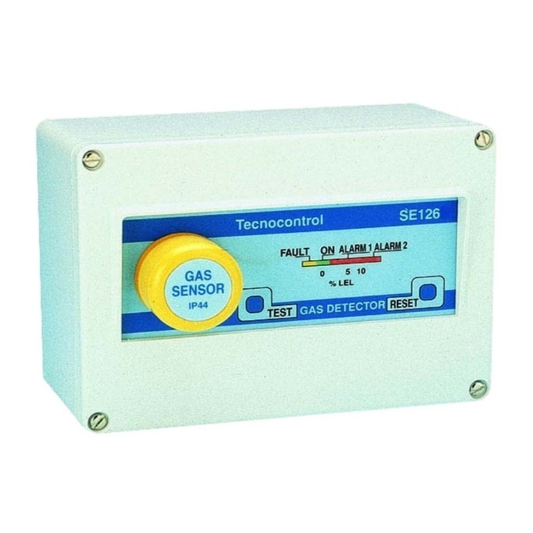
SE120KM - SE120KG
Tecnocontrol ONFAULT
METHANE GAS DETECTOR
SE120KM
ALARM Tecnocontrol ONFAULT
GPL GAS DETECTOR
SE120KG
ALARM
Caratteristiche tecniche / Technical specifications / Technické špecifikácie
Alimentazione / Power supply / Napájanie (cdV032 -15/+10%) - 2VA
Temp./umidità di funzionamento / Operation Temp./Humidity / Prevádzková
teplota a vlhkosť
-5 ÷ +40 °C / 30÷90 % RH
Temp./umidità di immagazzinamento / Storage Temp./Humidity / Teplota
a vlhkosť skladovania
-15 ÷ +50°C / 30÷90 % RH
Sensore / Sensor / Snímač /ocitilataC Catalityc / Katalytický
Intervento allarme / Alarm intervention / Úroveň alarmu 10% LIE / LEL (dolnej medze výbušnosti)
Tempo ritardo all’accensione / Time Delay at Switching on /
Časové oneskorenie zapnutia
50 secondi / seconds / sekúnd (±5”)
Tempo di ritardo allarme / Alarm Delay Time / Oneskorenie alarmu 15 secondi / seconds / sekúnd (±5”)
Dimensioni / Size / Rozmery / Ochrana skrinky 04PI/mm34x56x601
DESCRIZIONE
Il segnalatore di gas è in grado di forni-
re un segnale d'allarme ottico ed acu-
stico quando, nell'ambiente in cui è in-
stallato, avviene una fuga di gas. Ède-
stinato al’utilizzo civile cin installazione
di tipo fisso.
Il segnalatore utilizza un sensore di tipo
catalitico ed è prodotto in 2 versioni:
il Mod.SE120KM va utilizzato in im-
pianti alimentati a Metano.
il Mod.SE120KG per quelli a GPL.
I segnalatori sono tarati con lo specifico
gas al 10% LIE (Limite Inferiore di E-
splosività).
FUNZIONAMENTO
Sul frontale del segnalatore sono pre-
senti tre Led:
♦Verde indica la presenza
dell’alimentazione.
♦Giallo s'illumina in caso di guasto
“FAULT” del sensore.
♦Rosso indica una situazione d'allar-
me.
Nota: Ogni volta che il segnalatore vie-
ne alimentato per la prima volta o
dopo un periodo d'inattività, il Led
Rosso può accendersi, ma le sue fun-
zioni d'allarme (Cicalino) rimangono
bloccate per 85 secondi (±5") per per-
mettere al sensore di riscaldarsi.
GENERAL INFORMATION
The instrument is a wall mounted gas
detector for domestic application em-
ploying a catalytic sensor.
The unit offers both an alarm sound
and a LED indication in case a gas leak
occurs in the room where the instru-
ment is installed.
Two different models are available:
SE120KM should be used with
Methane plants.
SE120KG should be used with LPG
plants.
The calibration is carried out with spe-
cific gas at 10% LEL (Lower Explosion
Limit).
OPERATIONAL DESCRIPTION
On the gas detector front panel three
LEDs are available.
♦The green LED refers to power sup-
ply working.
♦The yellow LED provides a sensor
fault indication.
♦The red LED provides an alarm indi-
cation.
Note: when the instrument is powered
for the first time or after a long time
inactivity, the buzzer alarm function is
interrupted for 85 seconds (±5") to allow
the sensor heating. During this time the
red LED illuminates.
VŠEOBECNÝ POPIS
Detektor plynu je prístroj inštalovateľnýna stenu
pre domáce použitie s katalyzickým snímačom.
Jednotka poskytuje zvukový aj svetelný alaram
(červená LED) v prípade výskytu plynu a prekro-
čenia alarmu v miestnosti, v ktorej je detektor
nainštalovaný.
Dodávané sú dva modely:
SE120KM môže byť použitý pre detekciu
metánu (CH4).
SE120KG môže byť použitý na detekciu LPG.
Kalibrácia sa vykonáva pomocou špecifického
kalibračného plynu s koncentráciou na úrovni
10 % LEL (Dolnej medze výbušnosti).
POPIS FUNKCIE
Na prednom paneli detektora sú 3 LED.
Zelená LED dióda indikuje správne napájanie.
Žltá LED dióda indikuje poruchu snímača.
Červená LED dióda indikuje alarmový stav.
Poznámka: keď je prístroj napájaný po prvýkrát
alebo po dlhšej dobe nečinnosti, funkcia bzučiaku
alarmu je prerušená po dobu 85 sekúnd, počas
ktorej sa snímač zahrieva. Počas tejto doby
svieti červená LED.
♦
♦
♦
Pag./Str. 2/4K021ES-I10.20MK.0212-TSI
TECNOCONTROL S.r.l: Via Miglioli 97 SEGRATE 4373312/20:xaF09822962/20:leT)IM(
Dopo questo tempo il segnalatore è in
grado di funzionare regolarmente an-
che se necessita di 2÷3 ore per ripor-
tarsi nelle condizioni di stabilità e sensi-
bilità ottimali.
In condizione d'allarme, s'illumina il Led
Rosso (ALARM) e il segnale acustico
interviene dopo 15÷20 secondi. Se la
presenza del gas non è costante, il ri-
tardo riparte da zero. La condizione di
allarme termina quando la concentra-
zione del gas nell'ambiente diminuisce
sotto all'80% del punto di taratura.
INSTALLAZIONE
Posizionamento del Mod.SE120KM:
il Metano (CH4) è un gas più leggero
dell'aria, la densità relativa all'aria è
0,55, il suo LIE (Limite Inferiore di E-
splosività) è 5%v/v (Volume).
Il segnalatore va posto a 30 cm dal sof-
fitto, ad una distanza di 1-1,5 metri dal-
l'utilizzatore, ma non oltre i 3-4 metri e
lontano dagli angoli del locale o da pre-
se di ventilazione (Fig.1).
Il segnalatore non va installato in posi-
zioni con scarsa ventilazione; come ad
esempio tra soffitto e armadietti alti, so-
pra porte e finestre o sopra fonti di calo-
re quali frigoriferi, forni, lavabiancheria o
sopra il lavello.
Posizionamento del Mod.SE120KG:
il GPL è una miscela composta dal 20-
30% di Propano (C3H8) e dal 80-70% di
Butano (C4H10). La taratura per GPL
eseguita come richiesto dalla Norma
UNI-CEI 70028 con iso-Butano che è
un gas più pesante dell'aria, la densità
relativa all'aria è 2, il suo LIE è 1,8%v/v.
Il segnalatore va posto a 30 cm dal pa-
vimento, ad una distanza di 1-1,5 metri
dall'utilizzatore, ma non oltre i 3-4 metri
e lontano dagli angoli del locale o da
prese di ventilazione (Fig.2).
Il segnalatore non va installato in posi-
zioni con scarsa ventilazione; come ad
esempio dietro ad armadietti o tende,
vicino a porte, o vicino a fonti di calore
elevate.
Fissaggio e Collegamenti elettrici:
Per accedere ai morsetti, aprire la cu-
stodia infilando, nell'apposita fessura,
un adeguato cacciavite a taglio. Il se-
gnalatore è predisposto per l'installa-
zione a parete. (Fig.3):
1)praticare nel muro due fori con inte-
rasse 70 mm (A)
2)inserire i due tasselli a muro Ø 6 mm
in dotazione (B)
3)fissare la staffa con le due viti au-
tof.TC3,5x35 mm in dotazione (C).
4)infilare il segnalatore sulla staffa (D).
After this delay the instrument is
working correctly. However the gas
detector needs about 2÷3 hours'
time to get the stability and sensitiv-
ity conditions as to factory labora-
tory calibration.
In case of an alarm condition, the red
LED illuminates. After 15÷20 seconds
the buzzer activate. During this lapse of
time, if the gas concentration either is
not constant or fluctuates around the
calibration point, the time delay restarts
from zero. When the gas concentration
in the environment decreases below
80% of the calibration point, the red
LED switches off and the buzzer stops.
INSTALLATION
Model SE120KM positioning:
Methane (CH4) is a combustible
gas lighter than air. Its density re-
lated to air is 0.5-0.65; its LEL
(Lower Explosion Limit) is 5% v/v
(Volume).
The instrument should be fixed at 30
cms from the ceiling and be placed at
1-1.5 meter from the gas appliance (no
more than 3-4 meters), far from the
room corners or from ventilation intakes
(see Fig. 1).
Avoid installing the detector in low
ventilated environments such as be-
tween the ceiling and high cup-
boards, over windows and doors, or
over heating sources such as re-
frigerators, ovens, washing ma-
chines or over the sink.
Model SE120KG positioning: LPG
is a gas mixture composed by 20-
30% Propane (C3H8) and by 70-
80% Butane (C4H10). As per thye
Italian Standard CEI UNI CIG
70028, LPG calibration must be car-
ried out with Butane which is a
combustible gas heavier than air. Its
density related to air is 2; its LEL is
1.5%v/v .
The instrument should be fixed at
30 cms from the floor and be placed
at 1-1.5 meter from the gas appli-
ance (no more than 3-4 meters), far
from the room corners or from venti-
lation intakes (see Fig.2).
Avoid installing the detector in low
ventilated environments such as
behind cupboards or curtains, near
doors or high heating sources.
Mounting and Wiring connection:
To get access to the terminals,
open the case by inserting a screw-
driver in the suitable slot.
The gas detector can be wall
mounted (Fig. 3):
Po tomto oneskorení bude prístroj pracovať
správne. Avšak detektor plynu potrebuje
asi 2-3 hodiny na stabilizáciu a dosiahnutie
správnej citlivosti, ktorá je rovnaká ako
pri kalibrácii v laboratóriu výrobného
závodu.
V prípade alarmového stavu sa rozsvieti
červená LED dióda na prednom paneli. Po
15 - 20 sekundách sa aktivuje bzučiak.
Počas tohto stavu, aj keď koncentrácia nie
je konštantná alebo kolíše okolo kalibrač-
ného bodu (10% LEL), časové oneskore-
nie sa bude počítať od nuly. Keď koncen-
trácia plynu v miestnosti klesne pod 80 %
hodnoty kalibračného bodu, červená LED
zhasne a bzučiak sa vypne.
INŠTALÁCIA
Umiestnenie detektora SE120KM:
Metán (CH4) je plyn ľahší ako vzduch. Jeho
hustota je 0,5 - 0,65 kg/m3; jeho LEL (dolná
medza výbušnosti) je 5% objemových.
Tento prístroj by mal byť umiestnený vo
vzdialenosti 30 cm od stropu miestnosti a
asi 1 - 1,5 m od plynového spotrebiča (nie
viac ako 3 - 4 m), ďalej od rohov alebo od
ventilačného vstupu (otvoru), pozri obr. 1.
Vyhnite sa inštalovaniu detektora na málo
vetrané miesta ako je priestor medzi stro-
pom a skriňou alebo do výklenkov, nad
okná a dvere alebo nad zdroje tepla ako sú
chladničky, elektrické rúry, umývačky riadu
a pod.
Umiestnenie detektora SE120KG:
LPG je zmes plynov propánu - C3H8 (20 -
30 %) a butánu - C4H10 (70 - 80 %).
Podľa talianskej normy CEI UNI CIG 70028
detektor LPG musí byť kalibrovaný butánom,
pretože tento plyn je ťažší ako vzduch. Jeho
hustota je 2 kg/m3; jeho LEL je 1,5 % obj.
Detektor by mal byť umiestnený vo vzdiale-
nosti 30 cm od podlahy a asi 1 - 1,5 m od
plynového spotrebiča (nie viac ako 3-4 m),
ďalej od rohov miestnosti alebo ventilačných
otvorov (pozri obr. 2).
Vyhnite sa inštalovaniu do slabo vetraných
miest, napr. vedľa skríň alebo závesov,
za dverami alebo v blízkosti zdrojov tepla.
Montáž na stenu a pripojenie kábla:
Pre prístup ku terminálom otvorte skrinku
vsunutím skrútkovača do medzery.
Detektor plynu je možné namomtovať
na stenu (obr. 3):
Pag. /Str. 3/4K021ES-I10.20MK.0212-TSI
TECNOCONTROL S.r.l: Via Miglioli 97 SEGRATE 4373312/20:xaF09822962/20:leT)IM(
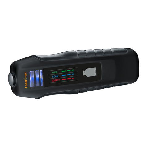
In figura 4è illustrato lo schema di col-
legamento all’alimentazione.
Il segnalatore di gas dovrebbe essere
collegato direttamente all'alimentazione
principale tramite connessione a fusibile
senza interruttore.
USO DEL RILEVATORE
Questa parte va letta attentamen-
te sia dall’installatore che
dall’utente.
NOTA: il segnalatore è tarato in
fabbrica utilizzando il gas specifico.
Il trimmer sigillato posto sul circuito
stampato dello strumento non deve
essere manomesso (pena la deca-
denza d'ogni garanzia e il pericolo
di rendere lo strumento insensibile
al gas).
GUASTI: in caso di guasto del sen-
sore s'illumina il Led Giallo “FAULT”
e viene emesso il segnale acustico.
Se si guasta il circuito d'alimenta-
zione, si spegne il Led Verde. In
questi casi consultare il proprio in-
stallatore.
VERIFICHE PERIODICHE:
si consiglia di far eseguire dal pro-
prio installatore una verifica del fun-
zionamento del segnalatore almeno
una volta l'anno. Per verificare il
funzionamento dell'apparecchio è
sufficiente tenere, per alcuni minuti
vicino al sensore, un batuffolo di co-
tone inumidito di alcool.
Attenzione: non utilizzare il gas
dell'accendino, in quanto il sensore
ne risulterebbe danneggiato in mo-
do irreversibile.
Il periodo di funzionamento del
segnalatore è normalmente 5 anni
dovuto alla vita media del sensore.
Al termine di questo periodo è pos-
sibile sostituire il sensore e ritarare
lo strumento con gas campione
presso il nostro laboratorio.
AVVERTENZE: Il segnalatore funziona
solo con l’alimentazione di rete 230Vca.
In caso di temporanea interruzione non
è in grado di funzionare.
Il segnalatore, non è in grado di rivelare
perdite che avvengano fuori dal locale
in cui è installato oppure all'interno dei
muri o sotto al pavimento.
Il sensore è resistente a prodotti d'uso
comune quali spray, ammoniaca, alco-
ol, colle o vernici. Questi prodotti, in
quantità elevate, possono provocare
falsi allarmi. Si consiglia di ventilare il
locale quando si utilizzano questi pro-
dotti.
1)Make 2 holes at 70mm of dis-
tance (A).
2)Insert the two screw anchors (Ø
6mm) supplied (B).
3)Fix the flask by using 2 self-
tapping screws(C) TC3.5x35 mm.
4)Let the gas detector slip on the
flask(D).
Fig. 4 shows, the power supply
connection diagram. The gas detec-
tor must be connected directly to
the main power supply using fuse
connection (without switch).
USING THE GAS DETECTOR
This paragraph must be carefully
read by both the installer and the
end user.
NOTE: The gas detector is calibrated
in factory by using specific gas.
Therefore the sealed trimmer
placed on the instrument Printed
Circuit Board must not be tampered
with (under penalty of loosing any
warranty rights and the risk of mak-
ing the instrument sensor insensi-
tive to gas).
FAULTS: In case of sensor fault,
the yellow LED illuminates and the
buzzer emits a sound alarm.
In case of power supply circuit fault,
as well as in case of power supply
failure, the green LED switches off.
Contact the installer.
PERIODICAL TESTING:
We recommend to contact the in-
staller at least once a year for a
general verification.
Warning: Do not use lighter gas di-
rectly on the sensor since the sen-
sor could be irremediably damaged.
These gas detectors expected life is 5
years, this being due to the sensor ave-
rage lifetime.
After this period, it is possible to replace
the sensor and carry out the instrument
recalibration with sample gas in factory
laboratory.
CAUTION: Please remember that the
gas detector cannot work without
power supply.
The detector is not able to detect gas
leaks occuring outside the room where
it is installed, neither inside walls or un-
der the floor.
The sensor employed has a good resi-
stance towards products such as
sprays, detergents, alcohol, glues and
paints. However, these substances, if in
great quantity, could cause false a-
larms. We recommend to ventilate the
room should products like these be
used.
1) Vyvrtajte 2 diery vo vzdialenosti 70 mm (A).
2) Vložte do dier hmoždinky (prm. 6 mm) (B).
3) Zafixujte podložku pomocou dvoch skrutiek
3,5 x 35 mm.
4) Zasuňte a zafixujte skrinku detektora na
podložku.
Obrázok 4 ukazuje schému zapojenia napája-
cieho kábla. Detektor plynu musí byť pripojený
priamo na sieťové napätie 230 V s použitím
poistky (bez vypínača).
POUŽITIE DETEKTORA PLYNU
Tento odsek si pozorne prečítajte: rovnako
inštalatér ako aj koncový užívateľ.
POZNÁMKA: Detektor plynu je kalibrovaný
vo výrobe s použitím kalibračného plynu.
Preto trimer umiestnený na prístrojovej doske
je zapečatený. Keby bola pečať porušená, dôjde
ku strate záruky a nebezpečenstvu, že sa zmení
citlivosť snímača. Preto nezasahujte do ele-
ktrickej časti detektora a nesnažte sa otáčať
kalibračným trimrom.
PORUCHY: V prípade poruchy snímača sa
rozsvieti žltá LED dióda a bzučiak začne vydá-
vať zvuk alarmu.
Pri výpadku elektrického napätia alebo poruchy
elektrického okruhu, zelená LED dióda zhasne.
Kontaktujte elektrikára.
PERIODICKÉ TESTY:
Doporučujeme zabezpečiť kontrolu detektora
aspoň jedenkrát ročne za účelom zistenia
citlivosti snímača a funkčnosti alarmu.
POZOR: Nepoužívajte cigaretový zapaľovač
priamo na skúšanie detektora, pretože môžete
poškodiť snímač.
Priemerná doba životnosti týchto snímačov je
5 rokov. Po tejto dobe je možné vymeniť snímač
a musí sa vykonať kalibrácia prístroja pomocou
kalibračného plynu a postupu podľa výrobcu
v laboratóriu.
UPOZORNENIE: Pamätajte, že detektor nemô-
že pracovať bez elektrického napájania.
Detektor plynu nie je schopný zistiť netesnosti
a únik plynu mimo miestnosť, kde je nainštalo-
vaný.
Snímač má dobrú ododlnosť voči látkam ako sú
spreje, detergenty, alkohol, lepidlá a náterové
hmoty. Avšak tieto látky, ak sú použité vo
veľkom množstve, môžu vyvolať falošné alarmy.
Doporučujeme, aby v prípade použitia takýchto
látok, bola miestnosť vetraná.
:
Pag./Str. 4/4K021ES-I10.20MK.0212-TSI
TECNOCONTROL S.r.l: Via Miglioli 97 SEGRATE 4373312/20:xaF09822962/20:leT)IM(
Se un fornello rimane aperto, anche
per parecchi minuti, la quantità di
gas fuoriuscito, non provoca l'allar-
me del segnalatore. Infatti la quanti-
tà di gas è di sotto della soglia
d’allarme anche se è percettibile in
quanto addizionato con un odoriz-
zante particolarmente fastidioso.
ATTENZIONE! INTERVENTI DA PORRE
IN ATTO IN CASO DI ALLARME
♦Spegnere tutte le fiamme libere.
♦Chiudere il rubinetto del contatore del gas
o della bombola del GPL.
♦Non accendere o spegnere luci; non a-
zionare apparecchi o dispositivi alimentati
elettricamente.
♦Aprire porte e finestre per aumentare la
ventilazione dell'ambiente.
♦Se l'allarme cessa è necessario indivi-
duare la causa che l'ha provocato e prov-
vedere di conseguenza.
♦Se l'allarme continua e la causa di pre-
senza di gas non è individuabile o elimi-
nabile, abbandonare l'immobile e dall'e-
sterno avvisare il servizio d'emergenza.
70 mm
A
B
C
D
Fig. 3 Fissaggio a parete
Wall-mounted detector instruction
Montáž na stenu
Small gas quantities coming out
from left open cookers for some
minutes do not cause the gas de-
tector alarm signalling even if it is
clearly nose perceptible. To make
nose identifiable, gas is added with
a particularly disturbing smelling
substance.
WARNING! INTERVENTIONS TO CARRY
OUT IN CASE OF ALARM
♦Extinguish all naked flames.
♦Turn off the gas supply at the gas emer-
gency control and/or, with a LPG supply,
the storage tank.
♦Do not switch on or off any electrical
lights. Do not activate any electrically
powered device.
♦Open both doors and windows to in-
crease room ventilation. If the alarm
stops, it is necessary to identify the alarm
reason and act accordingly.
♦If the alarm condition continues and the
cause of the leak is not apparent and/or
cannot be corrected, vacate the premises
and immediately notify the gas emer-
gency service.
Fig.4 Schema di Collegamento
Wiring diagram
Schéma elektrického zapojenia
SE120K
230Vac
L N
Malé množstvo plynu, ktoré výjde napr. z
otvorenej plynovej rúry alebo šporáka
počas krátkej doby nevyvolajú alarm detek-
tora, aj keď bude plyn cítiteľný čuchom.
Do plynu sa pridáva merkaptám, preto aj
pri malom úniku je cítiteľný nosom.
UPOZORNENIE! ČO JE TREBA UROBIŤ
V PRÍPADE ALARMU?
Uhaste všetky otvorené plamene.
Uzavrite prívod plynu na hlavnom bezpečnostnom
ventile alebo ventil na plynovom zásobníku / fľaši.
Nezapínajte alebo vypínajte žiadny elektrický
vypínač (svetlo). Nezapínajte žiadny elektrický
prístroj alebo spotrebič.
Otvorte súčasne dvere aj okná, aby ste nabezpečili
čo najintenzívnejšiu ventiláciu. Ak sa alarm vypne,
je potrebné zistiť príčinu alarmu a vykonať patričné
opatrenie.
Ak sa alarm znovu aktivuje a príčina úniku plynu
nie je známa alebo ju nie ste schopný zistiť, opustite
objekt a zavolajte pohotovostnú službu.
♦
♦
♦
♦
♦
Min 1m
30cm
Max 3m
Fig.1 -Esempio d’installazione dell’SE120KM per Metano
Model SE120KM (Methane) positioning
Umiestnenie modelu SE120KM (Metán)
Min 1m
Max 4m
30cm
Fig.2 - Esempio d’installazione dell’SE120KG per GPL
Model SE120KG (LPG) positioning
Umiestnenie modelu SE120KG (LPG)
Predajca pre Slovensko:
Meratex, s.r.o.
Szakkayho 1
040 01 Košice
Tel.: 055/6711988
www.meratex.sk

This manual suits for next models

1

Other Tecnocontrol Gas Detector manuals

Tecnocontrol SE126K User manual

Tecnocontrol

Tecnocontrol SE126K User manual

Tecnocontrol SE296KM User manual

Tecnocontrol

Tecnocontrol SE296KM User manual

Tecnocontrol SE136IC2 User manual

Tecnocontrol

Tecnocontrol SE136IC2 User manual

Tecnocontrol TS293PM User manual

Tecnocontrol

Tecnocontrol TS293PM User manual

Tecnocontrol SE183K User manual

Tecnocontrol

Tecnocontrol SE183K User manual

Tecnocontrol SE182PM User manual

Tecnocontrol

Tecnocontrol SE182PM User manual

Tecnocontrol TS282EO User manual

Tecnocontrol

Tecnocontrol TS282EO User manual

Tecnocontrol TS220E User manual

Tecnocontrol

Tecnocontrol TS220E User manual

Tecnocontrol SE237K User manual

Tecnocontrol

Tecnocontrol SE237K User manual

Tecnocontrol Beta SE330K Series User manual

Tecnocontrol

Tecnocontrol Beta SE330K Series User manual

Tecnocontrol SE193K Series User manual

Tecnocontrol

Tecnocontrol SE193K Series User manual

Tecnocontrol TS293P Series User manual

Tecnocontrol

Tecnocontrol TS293P Series User manual

Tecnocontrol TS293KM User manual

Tecnocontrol

Tecnocontrol TS293KM User manual

Tecnocontrol SE138K User manual

Tecnocontrol

Tecnocontrol SE138K User manual

Tecnocontrol SE137PM User manual

Tecnocontrol

Tecnocontrol SE137PM User manual

Tecnocontrol SE126KM User manual

Tecnocontrol

Tecnocontrol SE126KM User manual

Tecnocontrol SE148K User manual

Tecnocontrol

Tecnocontrol SE148K User manual

Tecnocontrol SE126K User manual

Tecnocontrol

Tecnocontrol SE126K User manual

Tecnocontrol TS210 IC2 User manual

Tecnocontrol

Tecnocontrol TS210 IC2 User manual

Tecnocontrol TS293IM User manual

Tecnocontrol

Tecnocontrol TS293IM User manual

Tecnocontrol SE155M User manual

Tecnocontrol

Tecnocontrol SE155M User manual

Tecnocontrol TS292P User manual

Tecnocontrol

Tecnocontrol TS292P User manual

Tecnocontrol TS293PM User manual

Tecnocontrol

Tecnocontrol TS293PM User manual

Tecnocontrol SE221KM User manual

Tecnocontrol

Tecnocontrol SE221KM User manual

Popular Gas Detector manuals by other brands

BEINAT GS911K Installation and user guide

BEINAT

BEINAT GS911K Installation and user guide

Autronica AutoPath HC800 instructions

Autronica

Autronica AutoPath HC800 instructions

Comelit SE237EO user manual

Comelit

Comelit SE237EO user manual

GASTRON GTD-2000Tx instruction manual

GASTRON

GASTRON GTD-2000Tx instruction manual

Greystone Energy Systems CDD Installation and operating instructions

Greystone Energy Systems

Greystone Energy Systems CDD Installation and operating instructions

Hydro Instruments GA-170 Operation and maintenance manual

Hydro Instruments

Hydro Instruments GA-170 Operation and maintenance manual

Besantek BST-MG08 Manual instruction

Besantek

Besantek BST-MG08 Manual instruction

Bacharach H25-IR PRO manual

Bacharach

Bacharach H25-IR PRO manual

Geca CTR21/M user manual

Geca

Geca CTR21/M user manual

Alecto COA-26 manual

Alecto

Alecto COA-26 manual

AKO AKOGAS AKO-576410 instructions

AKO

AKO AKOGAS AKO-576410 instructions

BEINAT CHCO quick start guide

BEINAT

BEINAT CHCO quick start guide

FIBARO CO Sensor FGCD-001 user manual

FIBARO

FIBARO CO Sensor FGCD-001 user manual

Honeywell BW Clip Real Time Quick reference guide

Honeywell

Honeywell BW Clip Real Time Quick reference guide

Macurco DMK-1 Installation and operation instructions

Macurco

Macurco DMK-1 Installation and operation instructions

ION Panther user manual

ION

ION Panther user manual

GMI Gasurveyor 11-500 User handbook

GMI

GMI Gasurveyor 11-500 User handbook

TUYA WiFi-708 quick start guide

TUYA

TUYA WiFi-708 quick start guide

manuals.online logo
manuals.online logoBrands
  • About & Mission
  • Contact us
  • Privacy Policy
  • Terms and Conditions

Copyright 2025 Manuals.Online. All Rights Reserved.