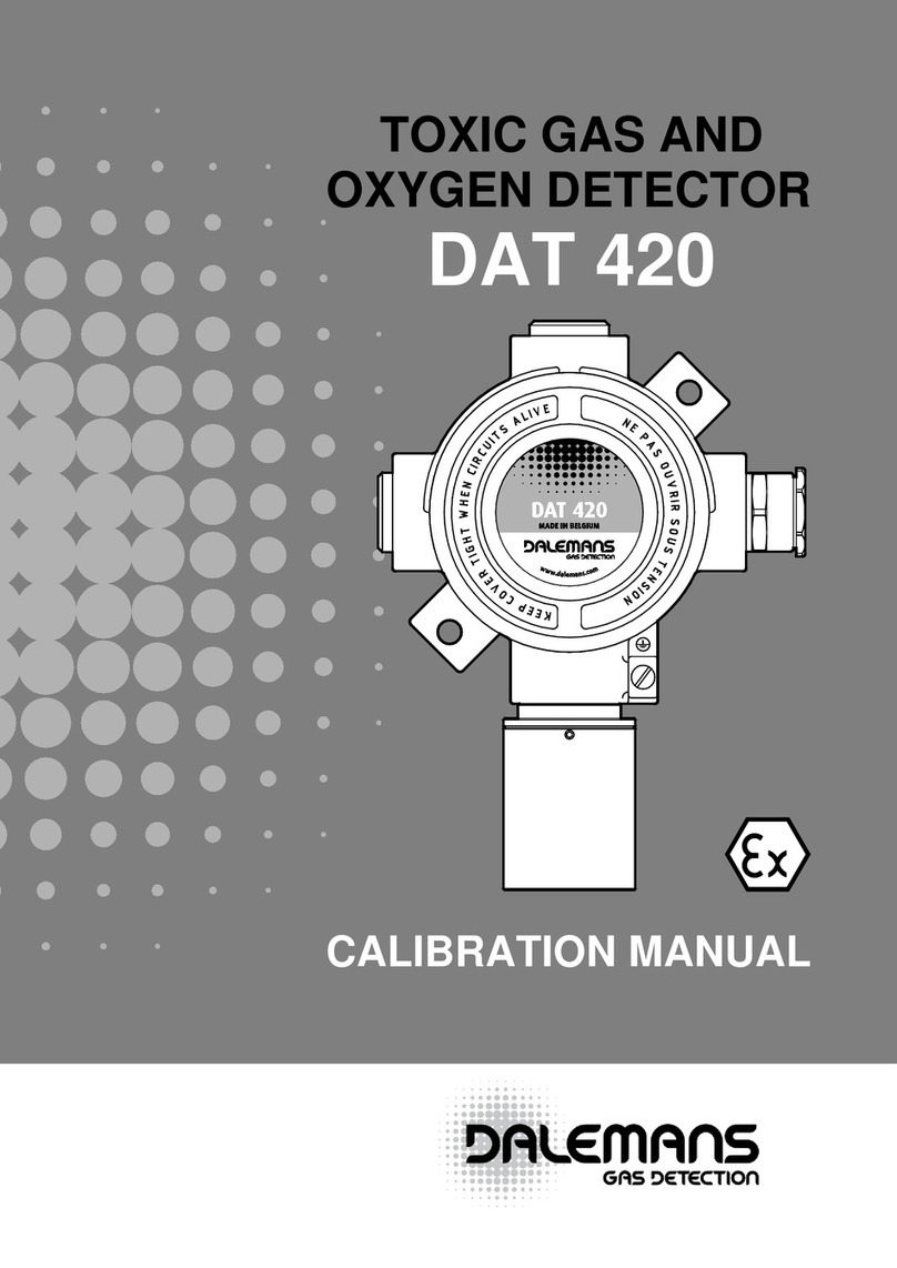
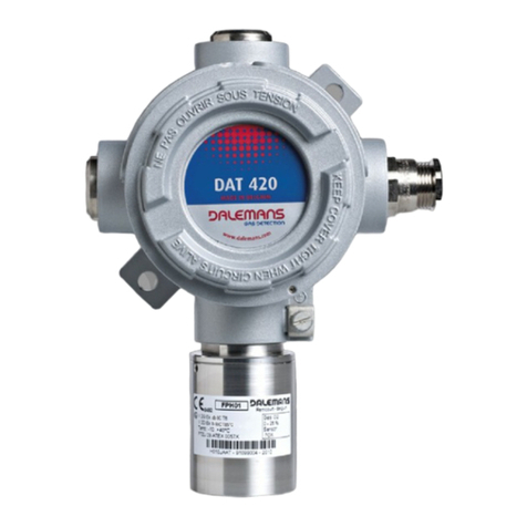
DALEMANS DAX 3F-I Assembly instructions

INSTALLATION, OPERATING AND
MAINTENANCE INSTRUCTIONS
DAX3FI_MAN01_EN
STAINLESS STEEL
FLAMMABLE GAS DETECTOR
DAX 3F-I
Ver. V1R2

1
DAX 3F-I
Introduction
These instructions must be read carefully by any person who has or will have the responsibility for
the installation, the use and/or the maintenance of this equipment. The warranty provided by
DALEMANS will be voided if installation, use and maintenance of this equipment are not in accor-
dance with the instructions given in this manual.
By respecting these instructions you guarantee the correct operation of the apparatus. Should you
require any further information about the use or the maintenance of this product, do not hesitate
to contact Dalemans PRIOR to carrying out installation works.
Each apparatus must be installed, operated and maintained according to the instructions, the
warnings and the operational limits detailed in this manual.
Use only DALEMANS original parts when you assume the maintenance of this product as specified
in this manual. The use of non-Dalemans spare parts may seriously impair the performances of the
apparatus. Repair or maintenance attempts carried out without observing the procedures
described in this manual or without the assistance of our after-sales service may prevent the
equipment from working properly and, consequently, from ensuring the safety of the occupants
of the building and of the plants.
!
Always make sure to switch off power and declassify the hazardous area before
carrying out replacement or modification works on components of the gas
detection system.
Application
The DAX 3F-I gas detector is suitable for use in hygienic and/or aggressive areas of industrial and
commercial environment. This apparatus is intended for use in explosive atmospheres of hazard-
ous areas (zone 1 or 2). The DAX 3F-I is designed to operate as part of a fixed gas detection system
and to provide, in association with a suitable control unit, early warnings of flammable gas hazard
before gas concentration reaches the Lower Explosive Limit (LEL).
For further information about the detectable gases or the list of the compatible control units,
please contact Dalemans.
Approval - Standards
As a manufacturer, Dalemans Company declares that the product described in this manual is certi-
fied for hazardous areas with an ingress protection degree IP6X and that it fulfils the requirements
of the following directives and standards :
• Directive94/9/EC(ATEX)
• EN60079-0:2006
• EN60079-1:2007
• EN60079-7:2007
• EN61241-0:2006
• EN61241-1:2004
The said products comply with the acceptable variations originating from the type that has
receivedtheEC-TypeExamination CertificateNrFTZU10ATEX 0034X.Moreover,they havebeen
designed, manufactured and controlled within the framework of an ISO9001 certified quality
assurance system which has been assessed by a notified body according to annex IV and VII of the
Directive94/9/EC.

2
DAX 3F-I
Gas: CH4
Use: -20..+70°C
100% LEL
1026
II 2D Ex tD A21 IP6X T135°C
II 2G Ex d e IIC T4
FTZU 10 ATEX 0034X
Tamb: -20°C to +90°C
DAX 3F-I
D050CCAB - 00263001 - 2010
Remicourt - BE
Marking
The label below is affixed to the junction box of the detector. This marking applies to the detector
overall assembly. The marking label affixed to the sensing head applies only to the sensing head.
Device Type
Notified Body
identification code
ATEX certificate number
Serial Nr - year of production
Target gas
Operating
temperature range
Measuring range
Certification (ATEX)
II :non-mining electrical equipment group for potentially explosive atmospheres.
2G :category 2 equipment intended for use in areas where GAS explosive atmospheres
are likely to occur (zone 1).
Ex d e :protection by flameproof enclosure “d” and increased safety “e”.
IIC :equipment group II subdivision according to the nature of the explosive GAS
atmosphere (methane, propane, ethylene, hydrogen, acetylene).
T6-T4 :temperature class according to the maximum surface temperature of the equip-
ment in explosive GAS atmosphere (T6=85 °C, T5=100 °C, T4=135 °C).
2D :category 2 equipment intended for use in areas where DUST explosive atmos-
pheres are likely to occur (zone 21).
Ex tD :dust ignition protection by enclosure “tD”.
A21 :method of determining the maximum surface temperature of equipment for use
in areas where an explosive atmosphere of combustible DUST is likely to occur,
occasionally, in normal operation (method A - zone 21).
IP6X :dust tight ingress protection.
Tx °C :maximum surface temperature of the equipment for DUST explosive atmospheres
(T85 °C, T100 °C or T135 °C).
Tamb :ambient temperature range according to the rated temperature class and the
maximum surface temperature.
For T6 and T85 °C
Tamb = -20 °C to +55 °C
For T5 and T100 °C
Tamb = -20 °C to +75 °C
For T4 and T135 °C
Tamb = -20 °C to +90 °C

3
DAX 3F-I
PC
A
Description
The DAX 3F-I is a gas detector designed to detect flammable gas present in ambient air at con-
centrations upto 100 % oftheLowerExplosive Limit (LEL). It operates usingacatalytic sensor
which providesa3-wiremVoutputsignal.TheDAX 3F-I detector can be connected to a control
unit as part of a Wheatstone bridge measuring circuit. For details of compatible control unit please
contact Dalemans.
The flammable gas detector DAX 3F-I comprises the following main parts :
• Thesensinghead.
• Thejunctionboxequippedwithaterminalblockforelectricalconnection.
• Thecablegland.
The overall assembly has a combined type of protection “d e” and an ingress protection IP6X.
Increased safety
“e” junction box
Flameproof “d”
sensing head
Increased safety
“e” cable gland
Mounting bracket
Increased safety
“e” terminal block
Figure 1 : DAX 3F-I detector

4
DAX 3F-I
Sensing head
The sensing element of the DAX 3F-I operates on the principle of catalytic combustion. The sensor
consists of a matched pair of elements typically referred to as a passive “P” element and an active
“A” element. Both are made of an electrically heated (400 °C) platinum wire coil embedded
within a bead. The bead of the active element is covered with a catalyst layer. The passive element
is used as a reference compensating for external temperature.
If combustible gas/air mixture is present in ambient air, catalytic combustion reaction takes place
on the active element. The heat of reaction on the catalyst layer produces a variation in the resis-
tance of the active element. This resistance variation, which is a function of gas concentration, can
bemeasuredbyacontrolunitequippedwitha3-wireWheatstonebridgeinput.
The Sensing head of the DAX 3F-I consists of :
• Aflameproof“d”sensorhousing(body+top).
• Asinteredmetalfilter.
• Acatalyticsensor(pellistor).
• Aplasticsensorsleeve(optionalaccordingtothetypeofsensor).
• AnO-ring.
The sensor housing is a stainless steel assembly (body and top) which can be dismantled to allow
plug-in sensor or sintered metal filter replacement.
Sensor sleeve
(optional)
Body
Sintered metal
filter
Top
Catalytic sensor
O-ring
Figure 2 : Sensing head

5
DAX 3F-I
Dimensions
Figure 3 : DAX 3F-I mechanical pattern
152.5
45
ø10
128.5
100
60
166
100
60
43
PC
A

6
DAX 3F-I
Caution
Detectors using catalytic sensors are not suitable for use in atmospheres with oxygen level over
21%,orbelow15%orvariable.
Atmosphereswith flammable gaslevelover100%LELmaydamagethecatalyticsensorinthe
long run. The sensor may become unusable after long periods of exposure to poisons such as sili-
cone, halogens, heavy metals.
Ensure that local or national regulations relating to the site or the monitored plant are met.
The operator must have knowledge of the safety procedure to follow in case of gas alarm.
Modification, disassembling and total or partial destruction of the sensing head and its contents,
of the cable gland or of the junction box and its contents, may invalidate the essential safety
requirements of the whole plant.
No additional drilling is allowed on the junction box. The existing openings cannot be enlarged.
Possible defective parts must be replaced by original parts delivered by Dalemans only.
No additional terminal can be installed on the existing terminal block. The length of the wires of
the sensing head may not be modified.
Do not open the junction box or the sensing head while explosion hazard might be present. Only
clean or wipe the detector surface with a wet cloth so as to avoid the risk of electrostatic sparks.
The detector must be protected from any risk of mechanical impact.
Flammable limits and setpoints
Relationshipbetween“percentofLowerExplosiveLimit”(%LEL)and“percentbyvolume”(%v/v)
differsfromgastogas.ThestandardIEC60079-20-1givesthemethodfordeterminationofflam-
mable limits.
• Ethane(C2H6) 100%LEL=2.4%v/v
• Ethylene(C2H4) 100%LEL=2.3%v/v
• Hydrogen(H2) 100%LEL=4.0%v/v
• Methane(CH4) 100%LEL=4.4%v/v
• Pentane(C5H12) 100%LEL=1.1%v/v
• Propane(C3H8) 100%LEL=1.7%v/v
Typicalalarmsetpointsforcombustiblegasdetectiondevicesare20%LELforthelowalarm(A1)
and40%forthehighalarm(A2).Neverusealarmsetpointsover60%LEL.
The LEL of a gas is affected by temperature and pressure. When the ambient temperature increases,
the LEL decreases and the explosion hazard is higher.
The relationship between LEL and pressure is very complex. However, a pressure increase usually
lowers the LEL.
The LEL of a gas is not significantly affected by the humidity fluctuations that may normally occur
in the average industrial environment.

7
DAX 3F-I
Installation & commissioning
I
nstallation and commissioning must be carried out by the manufacturer or his local representa-
tive. All the operations described hereafter can be carried out only by specialized personnel who
will have been trained beforehand exclusively by Dalemans.
Gas detection equipment should be installed as late as possible in any program of construction
operations (i.e. construction of a new plant, refitting or maintenance) but before the presence of
gas or vapours in the system, so as to avoid damage to sensors resulting in particular from such
activities as welding and painting. If already installed, sensors should be protected by an airtight
seal to avoid contamination during construction works, and should be clearly marked as being
non-operational.
Please follow the recommendations hereafter so as to avoid premature ageing of the detector and
to guarantee its optimal operation. These recommendations are general directives. Always refer
to local regulations/standards in force before proceeding with installation works (i.e. standards
IEC60079-14andIEC60079-29-2).Localregulations/standardsinforcehavealwaysprecedenceon
the recommendations of the manufacturer.
Location
Detectors must be placed so that potential gas accumulations are detected before they create a
significant hazard. Inappropriate location of a detector can nullify the effect and the integrity of
the gas detection system. The placement of the detectors should be determined in consultation
with experts having specialist knowledge of gas dispersion, with those who have knowledge of
process plant system and equipment involved, and with safety and engineering personnel. Should
you require any further guidance or assistance please contact Dalemans.
Detectors should be readily accessible to permit regular calibration, maintenance and electrical
safety inspection. It must be possible to access and fit all accessories or test equipment needed
for these operations on the detector. The location of every detector must be recorded and avai-
lable to the safety personnel. The following points should be taken into account when selecting
locations to install the gas detector :
• Hazardlevelandpotentialsourcesofgasleak.
• Thecombinationofsourcesofgasreleasewithpropagationeffects.
• Accessformaintenanceincludingcalibrationandverification.
• Protectionofthesystemagainstoperationalhazardsoftheplant.
• Protectionofthedetectoragainstmechanicalimpact.
• Vibrationisolationmountingsifnecessary.
• Thedetectorshouldneverbepositioneddirectlyaboveorbelowawaterpoint.
• Foroutdoorinstallation,aprotectionagainstrainand/orsunexpositionshallbeinstalled.
• Detectorshouldnotbelocatedinaircurrents,closetoairextractorsorinventilationducts.
• Alwaysobservetheoperationaltemperaturerangeofthesensor(refertospecifications).
• Iftargetgasislighterthanair(densitywithrespecttoair<1),placethe detector at a high level.
• Iftargetgasisheavierthanair(densitywithrespecttoair>1),placethe detector at a low level.
• If target gas has a unit weight close to air unit weight, place detectors at both high and low level.
• Gasdensityincreaseswhentemperaturedecreases.

8
DAX 3F-I
Examples of placement for some flammable gases * :
Gas Formula Density (air=1) Detector(s) position
Acetylene (CH)20.90 Ceiling+floor
Butane C4H10 2.05 Floor
Cracked gas -0.47 Ceiling
Ethylene oxide C2H4O1.52 Floor
Hydrogen H20.07 Ceiling
Isobutane (CH3)3CH 2.00 Floor
Methane CH40.55 Ceiling
Natural gas -0.68 Ceiling
Propane C3H81.56 Floor
Propane-air - ±1.15 Ceiling+floor
* This list is not exhaustive. Contact Dalemans for further information.
Mounting
The detector should be mounted flat on a wall and according to the mechanical pattern given in
figure3.
Attach the detector to the wall using the original external mounting brackets supplied with the
detector or using suitable screws and plugs for direct mounting. Unused holes of the junction box
must always be closed using the plastic plugs which are enclosed with the mounting kit.
The sensing head should never be installed pointing upwards. Make sure that dust will not block
the filter and that water will not run into the sensing head.
Figure 4 : Direct mounting
Junction box
M8 screw
Sealing serrated
washer

9
DAX 3F-I
Electrical wiring
Wiring must comply with local regulations and standards in force and meet the electrical require-
ments of the detector DAX 3F-I.
Dalemans recommends the use of colour coded cable. The acceptable cross sectional area of the
cableis1.5to2.5mm²dependingonthetypeofsensorusedandthedistancebetweenthedetec-
tor and the control unit. For more information about the cross sectional area of the cable and the
maximum cable length, please refer to the instruction manual of the control unit. The overall cable
diameter must be within the range given in figure 6 below. Cable gland must be sufficiently
tightened on the cable to ensure a good sealing.
Junction box
Mounting bracket
Other size
upon request
M8 hexagonal nut
Sealing serrated
lock washer
Washer
M8x16 screw
Figure 6 : Cable stripping
Figure 5 : Mounting for external brackets
6 mm
-
12 mm
15 mm 100 mm
8 mm MAX
1.5 - 2.5 mm²

10
DAX 3F-I
PC
A
To connect the detector :
• Unscrewthefourscrewsofthejunctionboxcoverandremovethecover.
• Loosentheclampingnutofthecablegland.
• Insertthecableinthejunctionboxthroughthecableglandandtightentheclampingnut.
• Connectwiresaccordingtothediagramgiveninfigure7below.
• Wiresmustbestrippedandpluggedsothatthegapbetweentheinsulationandthemetallic
edge of the terminal connection does not exceed 1 mm distance.
• Equipotential bonding may be provided using either the internal earthing terminal or the
external connection. If the external connection is used, the cross sectional area of the bonding
conductorshouldbeofatleast4mm².
• Putthecoverbackinplaceonthejunctionboxandtightenthefourscrews.
P : passive
A : active
C : common
Clamping nut
WHITE
BLUE
RED
Equipotential
bonding connections
Figure 7 : Electrical connection

11
DAX 3F-I
Maintenance(accordingtoATEXDirective-AppendixIIart.1.0.3.)
Regularly remove dust from the sensing head and the junction box with a wet cloth ONLY so as to
limit the risk of electrostatic sparks.
The sintered metal filter must be checked and cleaned at least once a year. If contamination of the
filter by solvent, gas or gas vapour has occurred, the sensing head must be replaced and the
inspection interval should be reduced by a factor of 2.
Gas detection equipment must be calibrated at least once a year, in some cases three or four times
a year, or even more to mitigate the loss of sensitivity of the sensor. This calibration must be
performed according to the procedure given by the manufacturer or his local representative, and
in any case by qualified personnel who will have been trained by Dalemans.
WARNING! Declassify hazardous area PRIOR to operating maintenance, calibra-
tion or service works and check with a portable apparatus that no gas is present
in the atmosphere.
Sintered metal filter replacement
• UnscrewthesensingheadtopusingthesuitabletoolOUT00000113.
• Replacethesintermetalfilterwithanewone(MEC00000010).
• Screwupthesensingheadtopandtighten.
• Makesurethesensingheadisstillcorrectlyfastenedtothejunctionbox.
• PerformcalibrationaccordingtotheproceduregivenbyDalemansorhislocalrepresentative.
Sensing head replacement
Prior to replacing the detector sensing head, inhibit the safety function of the detector on the gas
detection system and secure any output device connected to the system to prevent unintended
actuations and false alarms.
• Unscrewthefourscrewsofthejunctionboxcoverandremovethecover.
• On the APC terminal block, disconnect the three wires (red, blue and white) of the sensing head.
• Unscrewthesensorheadandremoveit.
• ScrewupthenewsensingheadandtightenwithtoolOUT00000113.
• ConnectthethreewiresofthesensingheadontheAPCterminalblock(figure7):
- RED on terminal A
- BLUE on terminal P
- WHITE on terminal C
• Putthecoverbackinplaceonthejunctionboxandtightenthefourscrews.
• Poweronthedetectorandrestoreitssafetyfunctiononthegasdetectionsystem.
• PerformcalibrationaccordingtotheproceduregivenbyDalemansorhislocalrepresentative.

12
DAX 3F-I
Troubleshooting
The control unit gives a “Fault” signal for the detector :
• Checkwiringandconnections.
• Possibledefectinsensingheadconnection(APCterminalblock).
• Thesensorinsidethesensingheadmaybedisconnectedoroutoforder.
The detector gives a non-zero measure :
• Theremaybegasintheatmosphere.
The detector gives a non-zero measure even though no gas is present in the atmosphere :
•Performfullcalibrationofthedetector.
The detector measure is either too high or too low :
• Performfullcalibrationofthedetector.
The detector gives a null measure although gas is present in the atmosphere :
• Checkwiringandconnections.
• Checkifsinteredmetalfilterisnotblockedbydust.
• Ifsinteredmetalfilterpollutionisdetected,replacebothfilterandsensorandperformfullcali-
bration.
Spare parts
Article code
Bracket - mounting kit BOI00000148
Cablegland-ExeM20(6-12mm)-BRASS PRE00000029
Cablegland-ExeM20(6-12mm)-STAINLESSSTEEL PRE00000037
Instruction manual IMP00000044
Junction box - Ex e BOI00000196
Nut-M20metallic PRE00000022
O-ring for cable gland MEC00000012
O-ring for sensing head MEC00000040
Screw-M4x6mm VISVIS00042
Sensinghead-FPH02+DAL17 DET00000021
Sensinghead-FPH02+DAL21 DET00000022
Sensinghead-FPH02+DAL-AC(acetylene) DET00000028
Sensor-DAL17 BASDET00020
Sensor - DAL21 BASDET00033
Sensor - DAL-AC (acetylene) BASDET00030
Sensor sleeve MEC00000028
Sintered metal filter MEC00000010
Spanner for sensing head top OUT00000113
Terminalblock-Exe3p BOR00000089
Terminal block for earthing - Ex e BOR00000091

13
DAX 3F-I
Specifications
MODEL DAX 3F-I
Sensing head
Stainlesssteel1.4404(AISI316L)Sintered metal filter
Junction box
Cable gland Nickel plated brass or stainless steel
Dimensions / Weight 166x152.5x75mm/1140g
Sensor type / Signal Catalytic(Pellistor)/3-wiremV(Wheatstonebridge)
Measuring range 0-100%LEL
Resolution ±3%ofmeasuringrange<60%LEL
±5%ofmeasuringrange>60%LEL
Responsetime(T90) <30sec.
Expected operating life span >2years
Sensor characteristics * DAL17 DAL21 DAL-AC (acetylene)
Supply voltage 2.00V
+0.025
2.00V±0.10V 2.00V±0.10V
-0.075
Supply current 175mA±20mA 300mA 145-160mA
Power consumption 0.4W 0.75W 0.4W
Storage temperature -40°Cto+80°C
Operating temperature -20°Cto+55°CforT6temperatureclass
-20°Cto+70°CforT5andT4temperatureclass
Humidity Ambient:20-90%HR/Intermittent:10-99%HR
Pressure 90-110kPa
Cable cross sectional area 1.5-2.5mm²(solidwires)
Max. cable length Refer to the installation instructions of the control unit
Ingress protection IP6X (dust tight)
Cable entries 1xM20orM25/6-12mm(othersizesavailable)
Hazardous areas Zones 1 or 2 (gas) - Zones 21 or 22 (dust)
Equipment gas grouping IIC (methane, propane, ethylene, hydrogen, acetylene)
Standards EN60079-0:2006,EN60079-1:2007,EN60079-7:2007
EN61241-0:2006,EN61241-1:2004
Approval II2GExdeIICT6-T4
II2DExtDA21IP6XTx°C
Ambient temperature Tamb=-20°Cto+55°CforT6andT85°C
Tamb=-20°Cto+75°CforT5andT100°C
Tamb=-20°Cto+90°CforT4andT135°C
Certificate FTZU10ATEX0034X
* Please refer to the marking label of the sensing head.
* Ensure that the sensor electrical characteristics meet the capability of the associated control unit.

14
DAX 3F-I
Glossary
Ex d :modeofprotectionbyflameproofenclosure“d”incompliancewithstandardsEN60079-0
andEN60079-1applyingtoelectricalequipmentintendedforuseinexplosivegasatmospheres.
The parts which can ignite the explosive atmosphere are placed in an enclosure which can with-
stand the pressure developed during an internal explosion of an explosive mixture, and which
prevents the transmission of the explosion to the explosive atmosphere surrounding the enclosure.
Ex e :modeofprotectionbyincreasedsafety“e”incompliancewithstandardEN60079-7applying
to electrical equipment intended for use in explosive gas atmospheres. Additional measures are
applied so as to give increased security against the possibility of excessive temperatures and of
the occurrence of arcs and sparks in normal service or under specified abnormal operations.
Ex tD : mode of protection by enclosure “tD” in compliance with standards EN 61241-0 and
EN61241-1applyingtoelectricalequipmentforuseinpresenceofcombustibledust.Theprotec-
tion is based on the limitation of the maximum surface temperature of the enclosure and on the
restriction of dust ingress into the enclosure to avoid ignition of a combustible dust layer or cloud.
94/9/EC :EuropeanCounciland Parliamentdirective(March23,1994)ontheapproximationof
the laws of the member states concerning equipment and protective systems intended for use in
potentially explosive atmospheres.
EN 60079-0 : standard general requirements applying to equipment intended for use in explosive
atmospheres.
EN 60079-1 :
standard applying to equipment protected by flameproof enclosure “d” and intend-
ed for use in explosive gas atmospheres.
EN 60079-7 : standard applying to equipment protected by increased safety “e” and intended for
use in explosive gas atmospheres.
EN 61241-0 : standard general requirements applying to electrical apparatus intended for use in
the presence of combustible dust.
EN 61241-1 :
standard applying to electrical apparatus protected by enclosure “tD” and intended
for use in the presence of combustible dust.
Environment - WEEE Directive
The crossed-out wheelie bin logo on this product indicates that you are held
to respect the regulation in force on the collection and recycling of Waste
Electrical and Electronic Equipment (WEEE).
These provisions are intended to preserve the natural resources used for
manufacturing this product and to avoid the dispersion of substances
potentially harmful for the environment and human health.
Therefore, to dispose of your end-of-life product, you MUST hand it over to a designated collection
point for the recycling of electrical and electronic Equipment. For further information about the
collection points in your area, contact your local city office.

DALEMANS s.a.
rue Jules Mélotte 27 • B-4350 Remicourt
Tel.: +32 (0)19 54 52 36 • Fax: +32 (0)19 54 55 34
info@dalemans.com
www.dalemans.com
OFFICIAL DEALER
Table of contents
Other DALEMANS Gas Detector manuals