DALEMANS DAT 420 Use and care manual

TOXIC GAS AND
OXYGEN DETECTOR
DAT 420
CALIBRATION MANUAL

www.dalemans.com
DAT420_MAN02_EN.docx • V1R1
i
DAT 420
RESPONSIBILITIES – WARRANTY
The fitter commits himself to comply with EC standards and with the installation instructions.
The installation must be carried out by qualified personnel.
All our products are tested and inspected before shipping.
These instructions must be read carefully by any person who has or will have the responsibility for the
installation, the use and/or the maintenance of this equipment. The warranty provided by DALEMANS will be
voided if installation, use and maintenance of this equipment are not in accordance with the instructions
given in this manual.
By respecting these instructions you guarantee the correct operation of the apparatus. Should you require
any further information about the use or the maintenance of this product, do not hesitate to contact
Dalemans PRIOR to carrying out installation works.
Each apparatus must be installed, operated and maintained according to the instructions, the warnings and
the operational limits detailed in this manual.
Use only DALEMANS original parts when you assume the maintenance of this product as specified in this
manual. The use of non-Dalemans spare parts may seriously impair the performances of the apparatus.
Repair or maintenance attempts carried out without observing the procedures described in this manual or
without the assistance of our after-sales service may prevent the equipment from working properly and,
consequently, from ensuring the safety of the occupants of the building and of the plants.
This device must be installed in a dry and clean place. Install a protection (housing) to avoid possible water
or poisoning agent projections.
Do not hesitate to contact us for any additional information about the use or the maintenance of this product.
Dalemans cannot be liable for direct or indirect damages arising out of the non-observance of its instructions.
Plans, schematics and information of this handbook are the property of Dalemans and could not be
reproduced or used without its prior agreement.
ENVIRONMENT
The crossed-out wheelie bin logo on this product indicates that you are held to respect
the regulation in force on the collection and recycling of waste electrical and electronic
equipments.
These provisions are intended to preserve the natural resources used for manufacturing
this product and to avoid the dispersion of substances potentially harmful for the
environment and human health.
Therefore, to dispose of your end-of-life product, you MUST hand it over to a designated
collection point for the recycling of electrical and electronic equipments. For further
information about the collection points in your area, contact your local city office.

DAT420_MAN02_EN.docx • V1R1
ii
DAT 420
Document : DAT420_MAN02_EN.DOCX
Version : V1R1
Date : 11/07/2011

www.dalemans.com
DAT420_MAN02_EN.docx • V1R1
iii
DAT 420
TABLE OF CONTENTS
1. WARNINGS ........................................................................................................................ 1
2. SPECIFICATIONS.............................................................................................................. 2
3. INTRODUCTION................................................................................................................. 3
4. EQUIPMENT REQUIRED................................................................................................... 4
5. SIMULATION OF THE 4..20 MA CURRENT LOOP.......................................................... 5
6. CALIBRATION OF DETECTOR......................................................................................... 6
6.1 Calibration mask, gas cylinder and voltmeter ..................................................................... 6
6.2 Calibration for toxic gases................................................................................................... 8
6.3 Calibration for oxygen ....................................................................................................... 10
6.4 Calibration conditions........................................................................................................ 11
7. TROUBLESHOOTING...................................................................................................... 12
8. ACCESSORIES AND SPARE PARTS ............................................................................ 12
ILLUSTRATIONS AND TABLES
Figure 1 : Exploded view of the detector....................................................................................... 3
Figure 2 : Calibration mask ........................................................................................................... 4
Figure 3 : Measurement probes .................................................................................................... 4
Figure 4 : Power supply and simulation of the 4..20 mA current loop........................................... 5
Figure 5 : Opening the FPH01 sensing head................................................................................ 6
Figure 6 : Installing the calibration mask and the voltmeter.......................................................... 7
Figure 7 : Calibration for toxic gases............................................................................................. 8
Figure 8 : Calibration for oxygen................................................................................................. 10
Table 1 : Technical specifications ................................................................................................. 2
Table 2 : Calibration parameters................................................................................................. 11
Table 3 : Troubleshooting............................................................................................................ 12
Table 4 : Accessories and spare parts........................................................................................ 12

www.dalemans.com
DAT420_MAN02_EN.docx • V1R1
1
DAT 420
1. WARNINGS
Prior to any service or maintenance attempt, ensure that local or national regulations relating
to the site or the monitored plant are met. The operator must have knowledge of the safety
procedure to follow in case of gas alarm.
Please follow the recommendations hereafter so as to avoid premature ageing of the detector and to
guarantee its optimal operation. These recommendations are general directives. Always refer to local
regulations/standards in force, such as the European directive 94/9/CE (Directive ATEX - annex II art. 1.0.3)
and, for example, the IEC 60079-14 and IEC 60079-29-2 standards, before proceeding with installation
works. Local regulations and standards in force always take precedence over manufacturer's
recommendations.
Gas detection equipment must be calibrated at least once a year, in some cases three or four times a year,
or even more to mitigate the loss of sensitivity of the sensor. This calibration must be performed according to
the procedure given by the manufacturer or his local representative, and in any case by qualified personnel
who will have been trained by Dalemans.
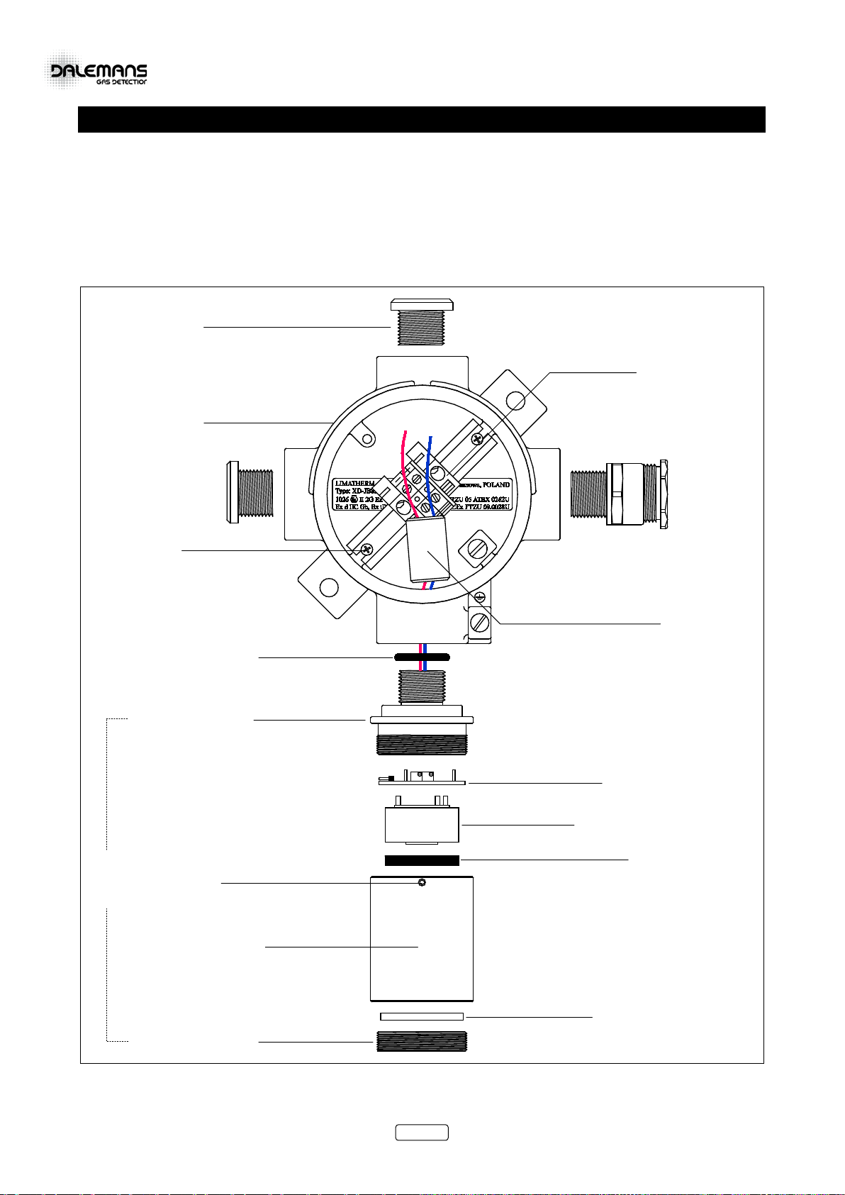
Modification, disassembling and total or partial destruction of the sensing head and its contents, of the cable
gland or of the junction box and its contents, may invalidate the essential safety requirements of the whole
plant.
No additional drilling is allowed on the junction box. The existing openings cannot be enlarged.
No additional terminal can be installed on the existing terminal block.
The length of the wires of the sensing head may not be modified.
Possible defective parts must be replaced by original parts delivered by Dalemans only.
Do not open the junction box or the sensing head while explosion hazard might be present. Only clean or
wipe the detector surface with a DAMP cloth so as to avoid the risk of electrostatic sparks.
Try to avoid, as much as possible, disconnecting the electrochemical sensor from the 4..20 mA transmitter or
storing the detector unpowered for a long period of time. These two situations might affect the sensor
performance and life-span.
Regularly remove dust from the sensing head and the junction box with a DAMP cloth ONLY so as to limit
the risk of electrostatic sparks.
The detector must be protected from any risk of mechanical impact.
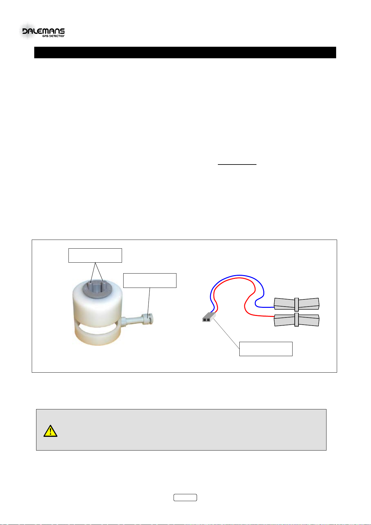
The sintered metal filter must be checked and cleaned at least once a year. If contamination of the filter by
solvent, gas or gas vapour has occurred, the sensing head must be replaced and the inspection interval
should be reduced by a factor of 2.
This document must be read in conjunction with the installation manual of the concerned apparatus.
Declassify hazardous area PRIOR to carrying out maintenance, calibration or service and
check with a portable apparatus that no gas is present in the atmosphere.
Ex

www.dalemans.com
DAT420_MAN02_EN.docx • V1R1
2
DAT 420
2. SPECIFICATIONS
MODEL DAT 420
Material
Sensing head
Sintered metal filter
Junction box
Stainless steel 1.4404 (AISI 316L)
Aluminium
Size / Weight 193 x 145 x 90 mm / 1500 g
Sensor type Electrochemical
Output signal 2-wire 4..20 mA current loop
End loop resistor 50 - 750 ohms
Adjustments Zero and calibration by internal potentiometers
Target gases *
Ammonia
Carbon monoxide
Chlorine
Hydrogen sulphide
Nitrogen dioxide
Oxygen
Sulphur dioxide
NH3
CO
Cl
H2S
NO2
O2
SO2
Range
100 ppm - 1,000 ppm - 5,000 ppm
300 ppm - 500 ppm - 1,000 ppm
10 ppm - 50 ppm
50 ppm
20 ppm - 50 ppm
25 %
20 ppm
Resolution ± 1.5 % full scale
Response time (T90) < 45 sec.
Expected operating life span > 2 years
Supply voltage 15 - 30 Vdc
Supply current Max. 30 mA
Storage temperature -40 °C to +80 °C
Operating conditions
Temperature range
Ambient humidity
Intermittent humidity
Pressure
-10 °C to +40 °C
20 - 90 % HR
10 - 99 % HR
90 - 110 kPa
Cable 2 x 0.5 mm² twisted and shielded pair (max. 1,000 m)
Cable entry 1 x M20 / 6.1 - 11.7 mm (other size available upon request)
Ingress protection IP6X (dust tight)
Approval
Hazardous areas Zone 1 or 2 (gas) - Zone 21 or 22 (dust)
Gas group IIC (methane, propane, ethylene, hydrogen, acetylene)
Marking II 2G Ex d IIC T6
II 2D Ex tD A21 IP6X T85 °C
Ambient temperature Tamb = -10 °C to +40 °C
Certificate FTZU 09 ATEX 0074
Standards EN 60079-0:2006, EN 60079-1:2007
EN 61241-0:2006, EN 61241-1:2004
* Non-exhaustive list. Other target gases are available upon request. Please contact Dalemans for further information.
Table 1 : Technical specifications

www.dalemans.com
DAT420_MAN02_EN.docx • V1R1
3
DAT 420
3. INTRODUCTION
The DAT 420 gas detector is comprised of:
•A junction box containing the connection terminals;
•The FPH01 sensing head, which contains an electrochemical sensor and the 4..20 mA transmitter.
For information concerning the installation and use of the DAT 420, refer to the instruction manual supplied
with the detectors, or contact Dalemans.
Figure 1 : Exploded view of the detector
FLAMEPROOF "d"
STOPPER PLUG
SINTERED METAL FILTER
SENSING HEAD BASE
FPH01 STAINLESS STEEL
FLAMEPROOF "d"
JUNCTION BOX
PRE00000033
BOI00000188
MEC00000010
VISVIS00042
M4X6 SCREW
ELECTROCHEMICAL SENSOR
DET00000019
4..20 mA TRANSMITTER
SENSOR GASKET
LOCKING SCREW
VISVIS00066
SENSING HEAD TOP
FPH01 STAINLESS STEEL
O-RING M20 X 17 X 2 mm
BASTRX00017
MEC00000018
MEC00000040
FERRITE
FER00000001
EX "e" TERMINAL
BLOCK 2P + DIN RAIL
BOR00000087
FLAMEPROOF "d"
M20 CABLE GLAND
PRE00000032
(6.1 - 11.7 mm)
OR
PRE00000036
(6.5 - 14 mm)
SENSING HEAD BODY
FPH01 STAINLESS STEEL

www.dalemans.com
DAT420_MAN02_EN.docx • V1R1
4
DAT 420
4. EQUIPMENT REQUIRED
Check that the following equipment is available in order to ensure that maintenance or calibration operations
on the detector may be completed successfully. For more information, do not hesitate to contact Dalemans.
•A cylinder of pure nitrogen;
•A cylinder of suitable calibration gas (concentration between 1/3 and 2/3 of the measuring range);
•A pressure-regulator with a flowmeter;
•A calibration mask (OUT00000089 - see figure below);
•A flexible hose made of Teflon, Polyurethane or PVC, with approximately 4 mm interior diameter
(TUB00000009);
•A measurement probes set fitted with a connector with a pitch of 2 mm (ACC00000012 - see figure
below);
•A digital voltmeter;
•A precision, insulated screwdriver;
•A 1.5 mm hexagonal key for the cover of the junction box (OUT00000115);
•A spanner for the top of the of the sensing head (OUT00000113);
•A 30 mm flat spanner for the base of the sensing head (OUT00000114).
Figure 2 : Calibration mask Figure 3 : Measurement probes
• To apply gas, ONLY use a Teflon, Polyurethane or PVC hose, not a silicone one!
• Check the validity date of the calibration gas cylinder!
• The connector of the measurement probe must have a pitch of 2 mm!
Ref. ACC00000012
PITCH = 2 mm
Ref. OUT00000089
INJECTION
END-FITTINGS
LOCKING SCREW

www.dalemans.com
DAT420_MAN02_EN.docx • V1R1
5
DAT 420
5. SIMULATION OF THE 4..20 MA CURRENT LOOP
In order to carry out the operations necessary for adjusting and calibrating the detector, it must be powered
up and connected to the 4..20 mA current loop of the control unit or the programmable controller (PLC) with
which it is associated. If not, it is possible to use the OctoPRO calibration unit to simulate the 4..20 mA
current loop. Contact Dalemans for further information.
The 4..20 mA current loop may also be simulated as follows:
1. Power the detector from a 24 VDC power supply;
2. Place a 270 ohms resistor in series, as shown in the figure below.
Only make the following connection if the detector is not already connected to the 4..20 mA
current loop of a measurement unit or a programmable controller.
Figure 4 : Power supply and simulation of the 4..20 mA current loop
POWER SUPPLY
24 VDC
+
-
.
LOOP RESISTOR
270 ohms

www.dalemans.com
DAT420_MAN02_EN.docx • V1R1
6
DAT 420
6. CALIBRATION OF DETECTOR
To properly calibrate the detector, the following operations must always be performed in the correct order :
1. Adjustment of the detector zero setting (ZEROING);
2. Adjustment of the detector sensitivity (CALIBRATION).
Avoid touching the transmitter circuit or any of the electronic components during the entire adjustment
procedure on the 4..20 mA transmitter inside the sensing head.
BEFORE opening the detector junction box or its sensing head :
•Check that the hazardous area has been declassified.
•Check, using portable equipment, that there is no dangerous gas present in the
atmosphere of the working area.
•Wipe the junction box and the sensing head with a DAMP cloth to minimize the risk of
electrostatic discharge.
6.1 CALIBRATION MASK, GAS CYLINDER AND VOLTMETER
Calibration consists of creating a calibration atmosphere around the sensing head by injecting a reference
gas. To avoid contamination of the calibration gas by the ambient atmosphere or air draughts, always use
the calibration mask supplied by Dalemans (Figure 2 - Page 4) to inject nitrogen or calibration gas.
To apply nitrogen or calibration gas on to the detector:
1. Screw the pressure-regulator/flowmeter onto the gas cylinder and tighten the connection.
2. Undo the locking screw of the sensor housing using the 1.5 mm hexagonal key (OUT00000115).
3. Unscrew the body and top assembly of the sensor housing using the OUT00000113 spanner and
the 30 mm flat spanner (OUT00000114). The flat spanner is positioned between the base of the
sensor housing and the box.
4. Connect one end of the flexible hose to the flowmeter outlet and the other end of the flexible hose to
one of the end-fittings on the calibration mask.
Figure 5 : Opening the FPH01 sensing head
30 mm FLAT SPANNER
OUT00000114
OUT00000113
1.5 MM HEX KEY
OUT00000115
LOCKING SCREW
SENSING HEAD
Ex

www.dalemans.com
DAT420_MAN02_EN.docx • V1R1
7
DAT 420
5. Place the calibration mask in the position of the body of the sensing head so that the connector of
the 40…200 mV output signal and the potentiometers of the 4..20 mA transmitter are accessible
through the slot in the side of the calibration mask. Tighten down the locking screw on the calibration
mask.
6. Using the measurement probes (Figure 3 - Page 4), connect the voltmeter across the connector of
the "40…200 mV" measurement signal as shown below.
Figure 6 : Installing the calibration mask and the voltmeter
CYLINDER +
REGULATOR
VOLTMETER
mV ═
+
-
+
-
LOCKING SCREW
CALIBRATION MASK
OUT00000089
"40..200 mV"
CONNECTOR
POTENTIOMETERS
FLEXIBLE HOSE

www.dalemans.com
DAT420_MAN02_EN.docx • V1R1
8
DAT 420
6.2 CALIBRATION FOR TOXIC GASES
NO2: for DAT 420 detectors fitted with a 0-20 ppm or 0-50 ppm nitrogen dioxide sensor,
use a calibration gas composed of NO2at 20 ppm in air!
1. During adjustment, avoid touching the transmitter circuit or its components with your fingers.
2. Allow the detector to be powered for at least 24 hours beforehand.
3. Position the calibration mask and connect the cylinder of nitrogen, the flowmeter and the voltmeter as
shown above.
4. Adjust the flow rate to between 0.4 and 0.6 l/min and apply nitrogen until the voltmeter display has
stabilised (min. 2 to 3 minutes).
5. On the transmitter, adjust the "ZERO" potentiometer (figure below) to obtain 40 mV ± 0.1 mV on the
voltmeter.
Figure 7 : Calibration for toxic gases
6. Stop applying nitrogen and wait until the 40…200 mV output signal is completely stable.
7. Replace the nitrogen cylinder with the cylinder of calibration gas and apply gas at a rate suitable for
the type of gas being used (see Table 2 - page 11). Wait until the voltmeter reading is completely
stable (see "Exposure" in Table 2 - page 11).
8. Adjust the "GAIN" potentiometer (figure above) to obtain a reading on the voltmeter corresponding to
the ratio between the calibration gas and the target measuring range.
This value is given, in mV, by the following formula :
104
420 ×+
−
×=
Range
Gas
CAL
Measure
V
CYLINDER +
REGULATOR
VOLTMETER
mV ═
+
-
+
-
"GAIN"
POTENTIOMETER
"ZERO"
POTENTIOMETER
VMeasure
.
ZERO
GAIN

www.dalemans.com
DAT420_MAN02_EN.docx • V1R1
9
DAT 420
Exemples :
Calibration gas
(CALGas)
ppm
Measuring range
300 ppm 500 ppm 1000 ppm 5000 ppm
IMeasure
mA VMeasure
mV IMeasure
mA VMeasure
mV IMeasure
mA VMeasure
mV IMeasure
mA VMeasure
mV
0 4.00 40.00 4.00 40.00 4.00 40.00 4.00 40.00
50 6.67 66.70 5.60 56.00 4.80 48.00 4.16 41.60
100 9.33 93.33 7.20 72.00 5.60 56.00 4.32 43.20
200 14.67 146.67 10.40 104.00 7.20 72.00 4.64 46.40
250 17.33 173.33 12.00 120.00 8.00 80.00 4.80 48.00
300 20.00 200.00 13.60 136.00 8.80 88.00 4.96 49.60
500 20.00 200.00 12.00 120.00 5.60 56.00
1000 20.00 200.00 7.20 72.00
2000 10.40 104.00
9. On the control unit/PLC to which the detector is connected, check that the reading corresponds
accurately to the value of the concentration of calibration gas applied.
10. Stop applying calibration gas, remove the calibration mask and check that the reading on the
voltmeter drops to its rest value of 40 mV and that the reading shown on the control unit/PLC drops to
zero.
11. Check that the sensor and transmitter are correctly positioned on their supports. Screw on the body of
the sensing head and tighten the locking screw (Figure 5 – Page 6).

www.dalemans.com
DAT420_MAN02_EN.docx • V1R1
10
DAT 420
6.3 CALIBRATION FOR OXYGEN
1. During adjustment, avoid touching the transmitter circuit or its components with your fingers.
2. Allow the detector to be powered for at least 24 hours beforehand.
3. Position the calibration mask and connect the voltmeter as shown above.
4. Connect the cylinder of nitrogen and the flowmeter to the calibration mask, as shown above.
5. Adjust the flow rate to between 0.4 and 0.6 l/min and apply nitrogen until the voltmeter display has
stabilised (min. 2 to 3 minutes).
6. On the transmitter, adjust the "ZERO" potentiometer (figure below) to obtain 40 mV ± 0.1 mV on the
voltmeter.
Figure 8 : Calibration for oxygen
7. Stop applying nitrogen, remove the calibration mask and leave the sensor in free air for 5 to 10
minutes so that the 40..200 mV output signal stabilises completely.
8. Adjust the "GAIN" potentiometer (figure below) to obtain a reading on the voltmeter that corresponds
to the concentration of oxygen in the atmosphere (20.9 %).
The value of the reading depends upon the measuring range :
Range
Concentration 20.9 %
With :
4
420 +
−
×=
Range
Gas
CAL
Measure
I
I
Measure
mA
V
Measure
mV
0 - 25 % 17.376 173.76
104
420 ×+
−
×=
Range
Gas
CAL
Measure
V
9. On the control unit/PLC to which the detector is connected, check that the reading corresponds
accurately to the concentration of oxygen in the atmosphere (20.9 %).
10. Check that the sensor and transmitter are correctly positioned on their supports. Screw on the body of
the sensor housing and tighten the locking screw (Figure 5 - Page 6).
CYLINDER +
REGULATOR
VOLTMETER
mV ═
+
-
+
-
.
.
ZERO
GAIN
"GAIN"
POTENTIOMETER
"ZERO"
POTENTIOMETER

www.dalemans.com
DAT420_MAN02_EN.docx • V1R1
11
DAT 420
6.4 CALIBRATION CONDITIONS
Gas Formula Remarks Min. Flow rate
(l/min) Exposure
(minutes)
Ammonia NH30.250 5
Arsine A5H30.250 2
Carbon monoxide CO 0.270 2
Chlorine Cl2Generator 0.420 2
Chlorine dioxide ClO2Generator 0.500 4
Diborane B2H60.300 2
Fluorine F2Calibration with Cl2generator - -
Hydrazine N2H4Gaseous permeation - 5
Hydrochloric acid HCl 0.300 3
Hydrocyanic acid HCN 0.250 1
Hydrofluoric acid HF 0.500 5
Hydrogen H21 % 0.270 1
Hydrogen H24 % 0.270 1
Hydrogen sulphide H2S 0.420 1
Nitrogen dioxide NO20.300 2
Nitrogen monoxide NO 0.300 2
Ozone O3Generator - 4
Phosgene COCl20.500 4
Phosphine PH3Calibration with A5H3- -
Silane SIH40.300 2
Table 2 : Calibration parameters

www.dalemans.com
DAT420_MAN02_EN.docx • V1R1
12
DAT 420
7. TROUBLESHOOTING
SYMPTOMS POSSIBLE CAUSE ACTION
Detector shows a non-zero
reading in the absence of gas.
Wear of measuring sensor.
Calibrate detector according to
procedure given above.
Calibration fault.
Detector shows a zero reading
in presence of gas.
Wiring fault.
Check detector wiring and connection
of sensing head.
Sintered metal filter either dirty or blocked. Clean or replace filter.
Sintered metal filter contaminated.
Replace filter;
Replace measuring sensor;
Calibrate detector.
Table 3 : Troubleshooting
8. ACCESSORIES AND SPARE PARTS
ACCESSORIES ARTICLE CODE
Calibration mask for FPH01 sensing head OUT00000089
Hose - PVC Ø 4 mm TUB00000009
Key for locking screw (1.5 mm hex key) OUT00000115
Measurement probes - Pitch = 2 mm ACC00000012
Spanner for the base of the sensing head (30 mm) OUT00000114
Spanner for the top of the sensing head OUT00000113
DAX 420 ARTICLE CODE
Cable gland - Ex d M20 (6.1 - 11.7 mm) PRE00000032
Cable gland - Ex d M20 (6.5 - 14 mm) PRE00000036
Ferrite FER00000001
Gasket for electrochemical sensor MEC00000018
Junction box - Ex d aluminium BOI00000188
Screw for locking the body of FPH01 sensing head VISVIS00066
Screw for locking the cover of the junction box VISVIS00067
Screw M4 x 6 mm VISVIS00042
Sensing head - FPH01 (without sensor) DET00000019
Sintered metal filter MEC00000010
Stopper plug - Ex d brass M20 x 1.5 mm PRE00000033
Terminal block - Ex e 2P + DIN rail BOR00000087
Transmitter - 4..20 mA TOX420 BASTRX00017
Table 4 : Accessories and spare parts

DALEMANS s.a.
Rue Jules Mélotte 27 • B-4350 Remicourt
Tel. : +32 (0)19 54 52 36 • Fax : +32 (0)19 54 55 34
www.dalemans.com
Other manuals for DAT 420
2
Table of contents
Other DALEMANS Gas Detector manuals
Popular Gas Detector manuals by other brands

LANDTEC
LANDTEC SEM5000 operating manual

Riken Keiki
Riken Keiki GD-F88Di operating manual

GMI
GMI Gasurveyor 11-500 User handbook

BW Technologies
BW Technologies GasAlertQuattro 1 Quick reference guide

Dräger
Dräger X-am 2800 Instructions for use

Helios
Helios KWL-VOC eC Installation and operating instructions

Geotechnics
Geotechnics MultiRAE Plus quick start guide

Prosense
Prosense PQ Series Quick installation guide

Southern Cross
Southern Cross Flame Pack 400 Series Operation and service manual

Medem
Medem SafeAir CM installation instructions

Raptor
Raptor R00189 user manual

Cosmos
Cosmos XA-440011 instruction manual