DANA SPICER TE27 User manual

Service Manual
Powershift Transmission
TE27 & TE32 4-SpeedLong Drop
with Full Flow Control Valve
TSM-0064
August 2012
80-1070 Rev 5/12/2014


TSM-0064 - TE27/32 4-Speed LD with Full Flow Control Valve Service Manual Dana Holding Corporation i
CONTENTS .................................................... i
Towing or Pushing ...........................................1
Introduction ..................................................... 2
Foreword .......................................................... 2
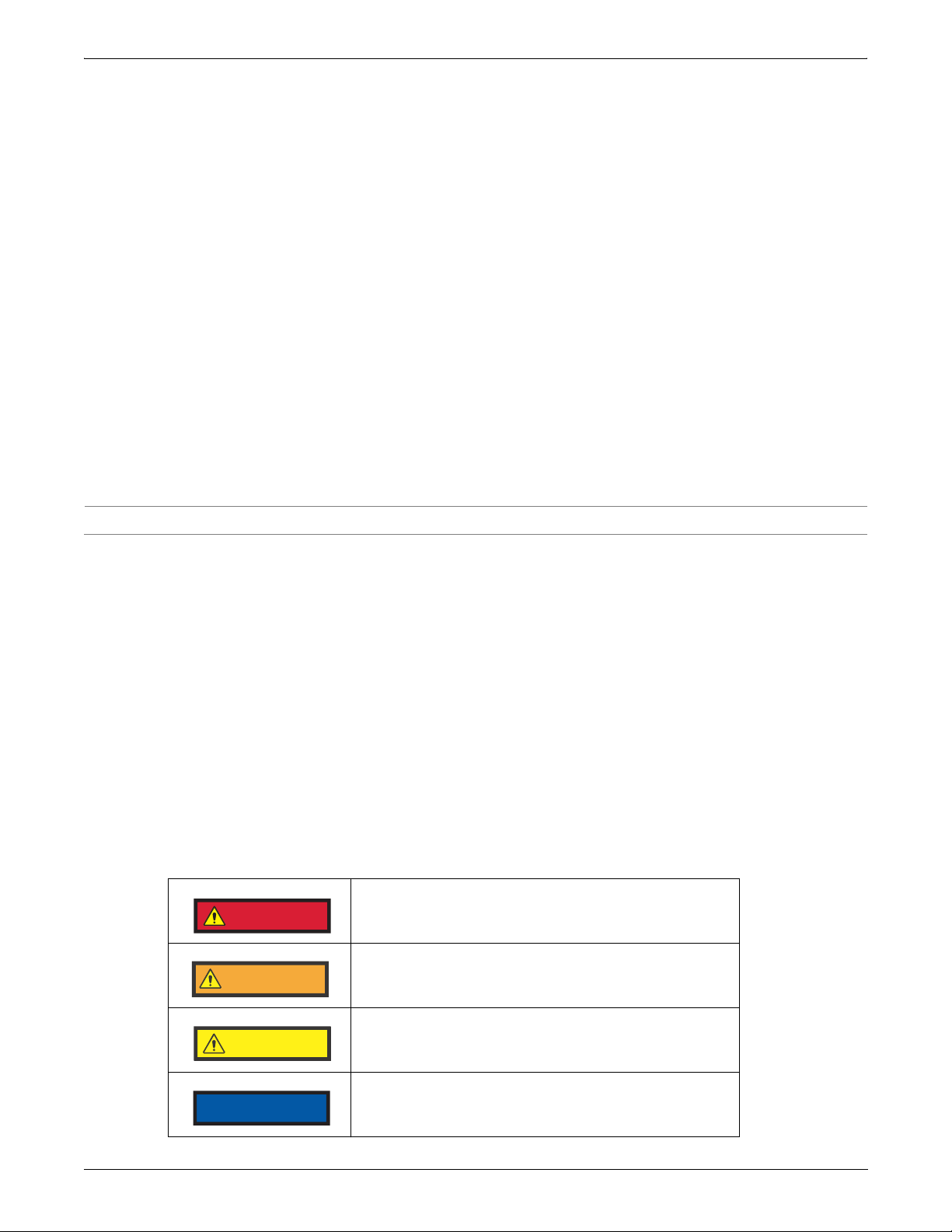
Safety Precautions ........................................... 2
SPECIFICATIONS ..........................................3
Identification Tag .............................................. 3
General Specifications ..................................... 3
Hydraulic Cooler Lines Specifications .............. 3
Pressure and Temperature Specifications ....... 4
Electrical Specifications ................................... 5
Maintenance ...................................................6
Sump preheaters ............................................. 6
Filters ............................................................... 6
Clutch Calibration ............................................ 6
Lubricants ........................................................ 6
Servicing Machine After Component Overhaul 7
Automatic Calibration Procedure ..................... 8
Drive Plate Installation .................................... 12
Transmission to Engine Installation ................13
EXTERNAL PLUMBING INSTALLATION .......14
SPEED SENSOR INSTALLATION ..................15
TEMPERATURE SENSOR INSTALLATION ...17
TRANSMISSION OPERATION .......................18
Converter, Pump Drive, & Pressure Regulating
Valve ................................................................ 19
Input Shaft and Directional Clutches ................ 20
Range Clutches ............................................... 21
Transmission Controls ..................................... 22
Electric Solenoid Controls ................................ 23
Power Flows, Activated Solenoids, & Hydraulic
Circuits ............................................................. 24
Gear & Clutch Layout ...................................... 42
TROUBLESHOOTING ....................................43
Transmission Problems ................................... 43
Troubleshooting Procedures ............................ 43
Troubleshooting Guide ..................................... 46
Check Points .................................................... 47
Checkports ....................................................... 50
Full Flow Valve Components ........................... 51
Speed Sensor Static Standalone Test .............. 52
EXPLODED VIEWS ........................................53
Converter Housing Group ................................ 53
Transmission Case & Rear Cover Group ........ 55
Turbine Shaft Group ........................................ 57
Charging Pump Drive Group ............................ 59
Torque Converter Assembly Group .................. 61
Forward, Reverse/Second, & Third or Fourth Clutch
Shaft Assembly ................................................ 63
Forward Clutch Shaft Group ............................ 65
Third Clutch Shaft Group ................................. 67
Third Speed Gear Group ..................................69
Reverse/Second Clutch Shaft Group ...............71
First Shaft Group ..............................................73
Fourth Clutch Shaft Group ...............................75
First Speed Gear Group ...................................77
Output Shaft Group ..........................................79
Regulator Valve Group .....................................81
Control Valve Group .........................................83
Remote Filter Adapter Group ...........................85
Converter Housing Cover Group ......................87
Input Flange Group ..........................................89
Idler Shaft Gear Group .....................................91
Idler Shaft Group ..............................................93
External Dipstick Group ....................................95
INSTALLATION DIAGRAMS ...........................97
Transmission Assembly Instructions ................97
Control Valve Assembly Instructions ................102
Cleaning and Inspection ..................................103
DISASSEMBLY & REASSEMBLY ...................104
Getting Started .................................................104
Transmission Case Disassembly ....................104
Converter Housing Disassembly ......................120
Reverse & Second Clutch Disassembly ...........121
Reverse & Second Clutch Reassembly ...........124
Forward Clutch Disassembly ............................128
Forward Clutch Reassembly ............................131
Third Clutch Disassembly .................................134
Third Clutch Reassembly .................................136
Fourth Clutch Disassembly ..............................138
Fourth Clutch Reassembly ...............................140
First Clutch Disassembly ..................................143
First Clutch Reassembly ..................................145
Idler Shaft Disassembly ....................................149
Idler Shaft Reassembly ....................................150
Turbine Shaft Disassembly ...............................150
Turbine Shaft Reassembly ...............................151
Impeller Disassembly .......................................152
Impeller Reassembly ........................................153
Impeller Cover & Turbine Disassembly ............155
Impeller Cover & Turbine Assembly .................155
Converter Cover Disassembly ..........................156
Converter Cover Reassembly ..........................156
Pump Drive Gear Disassembly ........................156
Pump Drive Gear Reassembly .........................157
Converter Housing Reassembly .......................157
Transmission Case Reassembly ......................159
TORQUE SPECIFICATIONS ..........................175
Lubricated or Plated Screws ............................175
Pipe Plugs ........................................................177
SPECIAL TOOLS ............................................178
CONTENTS

1 Dana Holding Corporation TSM-0064 - TE27/32 4-Speed LD with Full Flow Control Valve Service Manual
TOWING OR PUSHING
Before towing the vehicle, be sure to lift the driven axle wheels off the ground or disconnect the driveline to avoid dam-
age to the transmission during towing.
NOTE:
Because of the design of the hydraulic system, the engine cannot be started by pushing or towing.

TSM-0064 - TE27/32 4-Speed LD with Full Flow Control Valve Service Manual Dana Holding Corporation 2
INTRODUCTION
Foreword
This manual has been prepared to provide the customer and maintenance personnel with information and instructions
on the maintenance and repair of Dana Spicer products.
Extreme care has been exercised in the design, selection of materials, and manufacturing of these units. The slight out-
lay in personal attention and cost required to provide regular and proper lubrication, inspection at stated intervals, and
adjustments as indicated will be reimbursed many times in low cost operation and trouble-free service.
In order to become familiar with the various parts of the product, its principle of operation, troubleshooting, and adjust-
ments, it is urged that mechanics study the instructions in this manual carefully and use it as a reference when perform-
ing maintenance and repair operations.
Whenever repair or replacement of component parts is required, only Dana Spicer approved parts, as listed in the appli-
cable service parts list, should be used. Use of “will fit” or non-approved parts may endanger proper operation and per-
formance of the equipment. Dana does not warrant repair, replacement parts, or failures resulting from the use of parts
which are not supplied or approved by Dana.
IMPORTANT:
ALWAYS FURNISH THE DISTRIBUTOR WITH THE SERIAL AND MODEL NUMBER WHEN ORDERING PARTS.
Safety Precautions
To reduce the chance of personal injury and/or property damage, the following instructions must be carefully observed.
Proper service and repair are important to the safety of the service technician and the safe, reliable operation of the
machine. If replacement parts are required, the part must be replaced with a Dana specified replacement part. NEVER
use a replacement part of lesser quality.
The service procedures recommended in this manual are effective methods of performing service and repair. Some of
these procedures require the use of unique tools. Accordingly, anyone who intends to use a replacement part, service
procedure, or tool, which is not recommended, must first determine that neither their safety or the safe operation of the
machine will be jeopardized by the replacement part, service procedure, or tool selected.
It is important to note that this manual contains various precautions that must be carefully observed in order to reduce
the risk of personal injury during service or repair. Improper service or repair may also damage the unit or render it
unsafe. It is important to understand that these precautions are not exhaustive. It is impossible to warn of all possible
hazardous consequences that may result from following or failing to follow these instructions.
Indicates an imminently hazardous situation which,
if not avoided, will result in death or serious injury.
Indicates a potentially hazardous situation which,
if not avoided, could result in death or serious injury.
Indicates a potentially hazardous situation which,
if not avoided, may result in moderate or minor injury.
Indicates a situation which, if not avoided, may result
in damage to components.
DANGER
WARNING
CAUTION
NOTICE

3 Dana Holding Corporation TSM-0064 - TE27/32 4-Speed LD with Full Flow Control Valve Service Manual
SPECIFICATIONS
Identification Tag
The nameplate contains both the model and serial number of the unit.
General Specifications
Hydraulic Cooler Lines Specifications
Weight (dry) 2204 lbs / 1000 kg
Length (maximum) 39.8" / 1011 mm for T models
46.8" / 1189 mm for MT models
Width (maximum) 27.7"/ 703 mm
Height (maximum) 49.6"/ 1260 mm
Oil Capacity 7.9 US gallons / 30 liters*
* Without cooler and hydraulic lines. Consult equipment operator’s manual for complete system capacity.
Lines and Fittings (Minimum) 1" / 25.4 mm internal diameter
Continuous Operating Temperature Ambient to 248°F / 120°C
Continuous Pressure 406 PSI / 28 bar continuous pressure
and 595 PSI / 41 bar intermittent surges
Conformance SAE J1019 and SAE J517, 100RI

TSM-0064 - TE27/32 4-Speed LD with Full Flow Control Valve Service Manual Dana Holding Corporation 4
Pressure and Temperature Specifications
Normal Operating
Temperature
158–248ºF / 70–120ºC
Measured at temperature check port converter out
(port 71 or port 32*)
* Refer to “TROUBLESHOOTING” for check port identification.
Maximum Temperature 248ºF / 120ºC
Regulator Pressure†
† All pressures and flows to be measured with oil temperature 180-200ºF / 82-93ºC.
Vehicle in Neutral & Port 31*
At 600 RPM minimum: 326.3 PSI / 22.5 bar minimum
At 2650 RPM: 369.8 PSI / 25.5 bar maximum
Pump Flow†At 1900RPM
31.5 GPM / 119.3 l/min minimum
Lube Pump Flow At 2170 RPM selective lube
12.5 GPM / 47.2 l/min minimum
Clutch Pressure†
1st clutch: Port 41*
2nd clutch: Port 42*
3rd clutch: Port 43*
4th clutch: Port 44*
Forward clutch: Port 45*
Reverse clutch: Port 46*
At 2200 RPM:
297.3 PSI / 20.5 bar minimum with 1st clutch activated
Filter Bypass Valve†Set at 59.4-65.2 PSI / 4.1-4.5 bar†
Lube Pressure†
Port 34
58–80 PSI / 4.0–5.5 bar
at 2200 RPM
Internal Total Leakage
At 1000 engine RPM
FWD/REV: 1 GPM [4 l/min.] maximum
1st: 2.43 GPM [9.2 l/min.] maximum
2nd-3rd-4th: 1 GPM [4 l/min.] maximum
Converter: 1.3–3.2 GPM [5–12 l/min.] at 1000 RPM
Safety Valve
Cracking Pressure†127.6–139.2 PSI / 8.8–9.6 bar
Converter Out Pressure†
Port 33
72.5 PSI / 5 bar minimum
2000 RPM and maximum 123.3 PSI / 8.5 bar
at no load governed speed

Electrical Specifications
5 Dana Holding Corporation TSM-0064 - TE27/32 4-Speed LD with Full Flow Control Valve Service Manual
Electrical Specifications
Proportional Valves FWD/REV - 1st/3rd - 2nd/4th
Coil Resistance: 7.25:at 68°F / 20°C
Selection Valves
FWD/N/REV - 1st/3rd
Coil Resistance: 12V - 7.1:at 68°F / 20°C
Coil Resistance: 24V - 28.5:at 68°F / 20°C
Speed Sensor
Type: Magneto resistive sensor
Sensing Distance: 0–0.07"/ 0–1.8 mm
Sensor Signal: Generates a square current with a fixed
amplitude changing between 7 and 14 mA.
Temperature Sensor Material: Silicon
Resistance: 77°F / 25°C = 2000:+ 1%
Pressure Sensor
Supply Voltage: 4.5-5.5V
Maximum Current: 10mA
Pressure Range: 14.5-450 PSI / 1-31 bar
+1.2% full scale (450 PSI / 31 bar) range 14.5-363 PSI / 1-25 bar
+2.5% full scale (450 PSI / 31 bar) range 363-450 PSI / 25-31 bar

TSM-0064 - TE27/32 4-Speed LD with Full Flow Control Valve Service Manual Dana Holding Corporation 6
MAINTENANCE
Sump preheaters
Preheat the transmission fluid to the minimum temperature for the oil viscosity used before engine start up.
Filters
Service oil filter elements the first time at 100 hours and then every 1000 hours under normal environmental and duty
cycle conditions.
Clutch Calibration
Perform automatic clutch calibration every 2000 hours.
Lubricants
Recommended Lubricants
Only Dextron®III is approved. Viscosity at 104°F [40°C] = 33 - 38 cSt; at 212°F [100°C] = 7-8 cSt.
Maintenance Intervals
Daily
Check oil level daily with engine running at idle (600 RPM) and oil at 180-200°F [82 - 93°C].
Maintain oil level at full mark.
Normal oil change interval
Drain and refill system every 1000 hours for average environmental and duty cycle conditions. Severe or sustained high
operating temperature or very dusty atmospheric conditions will result in accelerated deterioration or contamination.
Judgement must be used to determine the required change intervals for extreme conditions.
Every 1000 hours:
•Change oil filter element.
•Drain oil at 150–200°F [65-93°C] and refill system as follows:
1. Drain transmission.
2. Remove and discard filter.
3. Install new filter.
4. Refill transmission to FULL mark.
5. Run engine at 500 - 600 RPM to prime converter and lines.
6. Recheck level with engine running at 500 - 600 RPM and add oil to bring level to LOW mark. When oil temperature
is hot 180-200°F [82.2-93.3°C] make final oil level check and adjust if necessary to bring oil level to FULL mark.
NOTE:
It is recommended that oil filter be changed after 100 hours of operation on new, rebuilt, or repaired unit.
Extended oil change interval
Extended oil service life may result when using synthetic fluids. Appropriate change intervals should be determined for
each transmission by measuring oil oxidation and wear metals, over time, to determine a baseline. Wear metal analysis
can provide useful information but a transmission should not be removed from service based solely on this analysis.

Servicing Machine After Component Overhaul
7 Dana Holding Corporation TSM-0064 - TE27/32 4-Speed LD with Full Flow Control Valve Service Manual
Servicing Machine After Component Overhaul
The transmission, torque converter, and its allied hydraulic system are important links in the driveline between the
engine and the wheels. The proper operation of either unit depends greatly on the condition and operation of the other.
Therefore, whenever repair or overhaul of one unit is performed, the balance of the system must be considered before
the job can be considered complete.
After the overhauled or repaired transmission has been installed in the machine, the oil cooler, and connecting hydraulic
system must be thoroughly cleaned. This can be accomplished in several manners and a degree of judgement must be
exercised as to the method employed.
The following are considered the minimum steps to be taken:
1. Drain entire system thoroughly.
2. Disconnect and clean all hydraulic lines. Where feasible hydraulic lines should be removed from machine for clean-
ing.
3. Replace oil filter element.
4. The oil cooler must be thoroughly cleaned. The cooler should be “back flushed” with oil and compressed air until all
foreign material has been removed. Flushing in direction of normal oil flow will not adequately clean the cooler. If
necessary, cooler assembly should be removed from machine for cleaning, using oil, compressed air, and steam
cleaner for that purpose.
IMPORTANT:
NEVER use flushing compounds for cleaning purposes.
5. Reassemble all components and use only type oil (See chapter 4.1.1 “Recommended lubricants”).
Fill the transmission through filler opening until fluid comes up to FULL mark on transmission dipstick.
•Remove filler plug and fill oil until FULL mark.
•Run engine two minutes at 500 - 600 RPM to prime torque converter and hydraulic lines.
•Recheck level of fluid in transmission with engine running at idle (500 - 600 RPM).
•Add quantity necessary to bring fluid level to LOW mark on dipstick.
•Recheck with hot oil 180 – 200°F [82.2 - 93.3°C].
•Adjust oil level to FULL mark on dipstick.
6. Recheck all drain plugs, lines, connections, etc… for leaks and tighten where necessary.
7. Perform automatic calibration.

TSM-0064 - TE27/32 4-Speed LD with Full Flow Control Valve Service Manual Dana Holding Corporation 8
Automatic Calibration Procedure
Introduction
The APC200 firmware contains an automatic transmission calibration procedure, which is able to optimize the shift
quality of the transmission.
An automatic calibration has to be done:
•When the vehicle is build at the OEM
•Every 2000 hours of transmission operation
•When an overhaul of the transmission is done
•When the transmission is repaired
•When the APC200 is replaced
ENTERING AUTOMATIC CALIBRATION MODE
The automatic calibration mode is entered by pressing the S-button on the APC200 display for 15 seconds during
power-up.

Automatic Calibration Procedure
9 Dana Holding Corporation TSM-0064 - TE27/32 4-Speed LD with Full Flow Control Valve Service Manual
PERFORMING AUTOMATIC CALIBRATION
Before the automatic calibration can be started, a number of conditions need to be fulfilled:
•The parking brake on the vehicle has to be activated.
•The transmission temperature needs to be above 60°C. See the next paragraph how to use the ‘HEAT’-mode
to do this in a time effective way.
•The engine speed has to be kept at around 800 rpm (± 200 rpm) during the complete calibration. If the APC200
has control over the engine, the engine speed will be adapted automatically.
1. If all the conditions mentioned above are met, the actual automatic calibration can be performed starting from the
following display on the APC200:
2. To trigger the automatic calibration procedure, push the S-button once. The APC200 display readout will show:
3. The APC200 asks for the shift lever to be put in FORWARD.
The automatic transmission calibration procedure starts. This is indicated on the APC200 display:
‘C1’ stands for ‘clutch 1’ being forward, while ‘M1’ stands for ‘mode 1’ of the calibration.
4. When all clutches have been calibrated, the APC200 displays:
5. At this point, the automatic calibration has completed successfully. The normal duration of a complete transmission
calibration is around 15 minutes.
6. To exit the automatic calibration mode, switch off the vehicle ignition key. Make sure that the APC200 has powered
down – wait for 2 seconds. Now restart the vehicle and the new tuning results will be activated automatically.
Troubleshooting
If anything different than described above appears on the APC200 display, there can be two possible reasons:
•The calibration conditions are not fulfilled (temperature is too low, parking brake switched off, the vehicle is
moving, engine rpm is too high or too low).
•A calibration error has occurred during the calibration. This message starts with an ‘E’ (see “CALIBRATION
CONDITION MESSAGES AND CALIBRATION ERRORS”, on page 11).
By selecting REVERSE on the shift lever, while the automatic calibration is performing, the procedure will abort the auto-
matic calibration immediately and restart the APC200. This feature can be used when something goes wrong during the
calibration procedure.
NOTE:
By aborting the automatic calibration, the calibration is not finalized and needs to be done from the beginning.

TSM-0064 - TE27/32 4-Speed LD with Full Flow Control Valve Service Manual Dana Holding Corporation 10
Automatic Calibration Procedure
HEATING UP THE TRANSMISSION BY USING THE ‘HEAT’-MODE
The ‘HEAT’-mode allows to select forward / reverse while the parking brake is activated, without forcing neutral and will
disable the inching and declutch function. During the heat mode the highest gear is forced – even when the shift lever is
in a lower gear. This combination allows the driver to heat up the transmission by going into stall.
‘HEAT’-mode can be activated in the same way automatic calibration mode is entered (see “ENTERING AUTOMATIC
CALIBRATION MODE”, on page 8). Once “tran” is displayed on the screen, press the M-button once to go into the
“HEAT”-mode. The APC200 will display:
To trigger the ‘HEAT’-mode, push the S-button. The APC200 will display the sump temperature:
This means the actual sump temperature of the transmission is 20°C.
Perform the following steps in order to heat up the transmission:
1. Make sure the parking brake is active and works properly.
2. Put the transmission in forward by selecting forward with the shift lever and then accelerates the engine to full throt-
tle.
3. Keep the engine at full throttle for about 15 seconds and then put the gearbox in neutral by selecting neutral with
the shift lever. Keep the engine at full throttle!
4. Keep the gearbox in neutral at full engine throttle for about 15 seconds again.
5. Release the throttle pedal and decelerate the engine to idle.
6. Go back to point 2 and repeat until the APC200 display shows a temperature above 140°F [60°C]. When the tem-
perature is above 140°F [60°C], the temperature indication on the display starts blinking. Now switch to automatic
calibration by pressing the M-button several times – until the APC200 displays “tran”.
During this warm up procedure, it is possible for the converter out temperature of the transmission to exceed the maxi-
mum limit. This is a consequence of heating up the transmission using this quick procedure. When this occurs, the
engine speed will be limited to half throttle when the APC200 has engine control or forcing neutral when the APC200
has no engine control. To solve this, simply leave the transmission in neutral for a minute and throttle the engine to
around 1300 rpm. This will allow the heat in the converter to be evacuated. After one or two minutes, resume the heat-
ing up procedure if the transmission temperature has not reached 60°C yet.

Automatic Calibration Procedure
11 Dana Holding Corporation TSM-0064 - TE27/32 4-Speed LD with Full Flow Control Valve Service Manual
CALIBRATION CONDITION MESSAGES AND CALIBRATION ERRORS
This chapter gives an overview of the most common calibration condition messages. Many calibration condition mes-
sages can be corrected, however, if any calibration error messages appear, contact the OEM of the machine.
Calibration Condition Messages
Calibration errors
Calibration errors have the form ‘E1.xx’ or ‘E2.xx’ (example: E1.25). Please contact the OEM of the machine if an error of
this form appears on the display.
The APC200 expects the shift lever to
be in NEUTRAL, but finds it in another
position.
(FORWARD or REVERSE)
Put the shift lever back in NEUTRAL.
THE APC200 expects the parking brake
to be ON while it is OFF. Put the parking brake ON.
The APC200 has detected output
speed.
Verify that the parking brake is ON and
working properly. If this is already the
case, keep the machine at standstill by
using the brake.
Once the machine has been stopped,
the APC200 will ask the driver to shift to
FORWARD before continuing the
calibration.
Engine RPM is to low according to the
limit that is necessary for calibration.
When during the automatic transmission
calibration the temperature becomes to
low, the APC200 display indicates the
actual transmission temperature.
Engine RPM is to high according to the
limit that is necessary for calibration.
After being to low or to high, the engine
RPM is coming back into the correct
boundaries for calibration.
When during the automatic transmission
calibration the temperature becomes to
low, the APC200 display indicates the
actual transmission temperature.
Use the M-button on the APC200 to go
back to the 'HEAT' mode and the S-but-
ton to trigger this mode. Then warm-up
the transmission again until the temper-
ature is above 140°F [60°C]. Then go
back to the automatic tuning mode by
the M-button and trigger this one again
to continue calibration.

TSM-0064 - TE27/32 4-Speed LD with Full Flow Control Valve Service Manual Dana Holding Corporation 12
DRIVE PLATE INSTALLATION
Proper identification is determined by measuring the bolt circle diameter (see dimension “A” in the illustration below)
and then ordering the appropriate drive plate kit from the table.
1. Position drive plate and weld nut assembly on torque converter assembly with weld nuts toward converter.
2. Align intermediate drive plates and backing ring with holes in torque converter assembly.
3. Tw o d i m p l es 1 8 0 oapart in backing ring must be facing outward toward engine flywheel (hollow side facing torque
converter assembly).
4. Install capscrews and lockwashers. Tighten capscrews to 30-37 lbs. ft. (40-50 N•m).
NOTE:
Assembly of all plates must be completed within 15 minutes from when screws are installed. If a screw is removed for any reason it must be
replaced. The adhesive left in the tapped holes must be removed with the proper tap and cleaned with solvent. Dry the hole thoroughly and
use a new screw for reinstallation.
Each kit includes:
2 Intermediate Drive Plates
1 Drive Plate & Weld Nut Assembly
1 Backing Ring
6 Mounting Capscrews
6 Lockwashers
Instruction Sheet
Each kit includes:
3 Intermediate Drive Plates
1 Backing Ring
6 Mounting Capscrews
6 Lockwashers
Instruction Sheet
15” [381.0 mm] diameter 15” [381.0 mm] diameter
16” [406.4 mm] diameter 16” [406.4 mm] diameter
17” [431.8 mm] diameter 17” [431.8 mm] diameter
BACKING RING
INTERMEDIATE
DRIVE PLATES (2)
DRIVE PLATE AND
WELD NUT ASSEMBLY (1)
BOLT CIRCLE
DIAMETER
"A"
BACKING RING
INTERMEDIATE
DRIVE PLATES (3)
BOLT CIRCLE
DIAMETER
"A"

13 Dana Holding Corporation TSM-0064 - TE27/32 4-Speed LD with Full Flow Control Valve Service Manual
TRANSMISSION TO ENGINE INSTALLATION
1. Remove all burrs from flywheel mounting face and
nose pilot bore. Clean drive plate surface with sol-
vent. Dry thoroughly.
2. Check engine flywheel and housing for conformance to
standards SAE #3 per SAE J-927 and J-1033 tolerance
specifications for pilot bore size, pilot bore runout, and
mounting face flatness. Measure and record engine
crankshaft end play.
3. Install two 2.50” [63.5 mm] long transmission to fly-
wheel housing guide studs in the engine flywheel hous-
ing as shown. Rotate the engine flywheel to align a drive
plate mounting screw hole with the flywheel housing
access hole.
4. *Install a 4.00” [101.6 mm] long drive plate locating stud
.3750-24 fine thread in a drive plate nut. Align the locat-
ing stud in the drive plate with the flywheel drive plate
mounting screw hole positioned in Step 3.
5. Rotate the transmission torque converter to align the
locating stud in the drive plate with the flywheel drive
plate mounting screw hole positioned in Step 3. Locate
transmission on flywheel housing.
6. Align drive plate to flywheel and transmission to fly-
wheel housing guide studs. Install transmission to fly-
wheel housing screws. Tighten screws to specified
torque. Remove transmission to engine guide studs.
Install remaining screws and tighten to specified torque.
7. *Remove drive plate locating stud.
8. Install drive plate attaching screw and washer. Snug
screw but d
do not tighten
. Some engine flywheel hous-
ings have a hole located on the flywheel housing cir-
cumference in line with the drive plate screw access
hole. A screwdriver or pry bar used to hold the drive
plate against the flywheel will facilitate installation of the
drive plate screws. Rotate the engine flywheel and
install the remaining seven (7) flywheel to drive plate
attaching screws. Snug screws but d
do not tighten
. After
all eight (8) screws are installed, tighten each capscrew
to 26-29 lbs. ft. (35-39 N•m). This will require tightening
each screw and rotating the engine flywheel until the full
amount of eight (8) screws have been tightened to
specified torque.
9. Measure engine crankshaft end play after transmission
has been completely installed on engine flywheel. This
value must be within 0.001” [0.025 mm] of the end play
recorded in Step 2.
10. Axial force acting on flywheel is continuous 940 N /
intermittent 1885 N.
11. Hose line operating requirements: Pressure lines
suitable for operating from ambient to 120°C contin-
uous operating temperature, must withstand 25 bar
continuous pressure, with 50 bar intermittent surges.
Reference SAE spec J-517, 100RI hydraulic hose
specification. All hose lines used must be conform to
SAE spec J-1019 tests and procedures for high tem-
perature transmission oil hose. All hose lines and fit-
ting have a 19 mm inside diameter unless noted.
* Does not apply to units having 3 intermediate drive plates. See Figure 4.
FLYWHEEL H OUSING
ENGINE
FLYWHEEL
FIG. 1
FLYWHEEL
PILOT BORE
MOUNT
DIAL INDICATOR
HERE
FLYWHEEL
FLYWHEEL HOUSING CONVERTER HOUSING
DRIVE
PLATE
4"STUD
2
1/2
"ALIGNING
STUDS
FIG. 3 FIG.4
FLYWHEEL HOUSING
SPECIAL STUD, WASHER AND
SELF LOCK NUT FURNISHED
BY ENGINE MANUFACTURER.
FLYWHEEL
IMPELLER
COVER
INTERMEDIATE
DRIVE PLATES
FIG. 5
PLATES TO BE INSTALLED
WITH CONCAVE SIDE
TOWARD ENGINE FLYWHEEL.

TSM-0064 - TE27/32 4-Speed LD with Full Flow Control Valve Service Manual Dana Holding Corporation 14
EXTERNAL PLUMBING INSTALLATION
Cooler & Filter Line Specifications
•Minimum 1" [25.4 mm] internal diameter for lines and fittings.
•Suitable for operation from ambient to 248°F [120°C] continuous operating temperature.
•Must withstand 435 PSI [30 bar] continuous pressure and with 652 PSI [40 bar] intermittent surges.
•Conforms SAE J1019 and SAE J517,100RI.
to remote filter 1
from pump 1
from remote filter 1
from remote filter 2
from transmission to cooler
from cooler to
transmission
Cooler
Remote Filter 1
to remote filter 2
from pump 2
Remote Filter 2

15 Dana Holding Corporation TSM-0064 - TE27/32 4-Speed LD with Full Flow Control Valve Service Manual
SPEED SENSOR INSTALLATION
The magneto resistive sensor generates a square wave current with a fixed amplitude changing between 7 mA and 14
mA. The sensor has an integrated AMP superseal 2-pin connector. The two pins are numbered 1 and 2.
The following table shows the relation between wire color, pin number and connection.
Pin / Color Function Connection
1 / Brown Current Input Hot Wire
2 / Blue Current Output Ground Wire
The sensor wires have a polarity. Be sure to correctly observe
sensor polarities as wrong connections will deactivate the sensor!
CAUTION

TSM-0064 - TE27/32 4-Speed LD with Full Flow Control Valve Service Manual Dana Holding Corporation 16
Speed Sensor Installation

17 Dana Holding Corporation TSM-0064 - TE27/32 4-Speed LD with Full Flow Control Valve Service Manual
TEMPERATURE SENSOR INSTALLATION
This manual suits for next models
1
Table of contents