Las cercas, portones y pestillos de las piscinas no sirven como substituto de la supervisión por parte de adultos. Si se usa este pestillo en un portón de piscina, consulte a todas las autoridades
locales correspondientes con respecto a los requisitos de seguridad. El pestillo funcionará debidamente sólo si se instala y mantiene de acuerdo a estas instrucciones.
MANTENIMIENTO: QUITE LA LLAVE DE LA CERRADURA DESPUÉS DE USARLA. No lubrique el pestillo con lubricantes aceitosos en ningún momento; use sólo grafito en polvo. Asegúrese de
haber ajustado todos los tornillos o tuercas firmemente y que el tirador de apertura [F] y el pestillo estén libres de arena, hielo u otros fragmentos que puedan impedir su eficaz funcionami-
ento. Esmerile o retire todo elemento de que sobresalga después de la instalación.
GARANTÍA Y LIMITACIÓN DE LA RESPONSABILIDAD: Los productos de D&D Technologies (D&D) llevan una garantía al comprador original, de que están libres de defectos de
materiales y mano de obra, mientras el producto pertenezca a dicha persona. Si aparece un defecto estructural, el comprador original podrá devolver el artículo, previo pago de flete, junto con
evidencia de compra, a D&D o sus agentes internacionales aprobados. D&D o su agente, a su discreción, repararán o reemplazarán el artículo defectuoso o parte defectuosa en forma gratuita.
ESTA GARANTÍA NO TENDRÁ APLICABILIDAD CUANDO se haya modificado el producto, cuando personas no autorizadas lo hayan reparado o intentado repararlo, cuando el artículo haya sido
objeto de uso incorrecto, abuso, o haya sufrido accidentes o daños en tránsito, o cuando la persona que lo haya instalado
no haya seguido, durante la instalación o funcionamiento, las instrucciones o los Requisitos de Mantenimiento que se establecen.
EN NINGÚN CASO LA EMPRESA SE HARÁ RESPONSABLE DE DAÑOS INCIDENTALES O EMERGENTES. No se otorga otra garantía
que la que se establece más arriba. No se aplica ninguna otra garantía, expresa o implícita (incluidas las garantías estatutarias),
a menos que sean garantías que no puedan excluirse por ley.
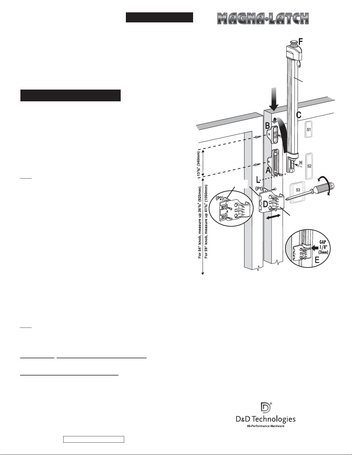
1. El espacio entre el marco del portón y el poste del pestillo deberá ser de entre 3/8” (10mm) y 17/16” (37mm); 3/4” (19mm) es
lo ideal.
2. Determine la ubicación del agujero para el Soporte de Montaje ‘A’, midiendo desde el suelo terminado/
superficie de fijación…
• para una altura de tirador de 54”, mida 363/8” (925mm) desde el suelo;
• para una altura de tirador de 59”, mida 413/8” (1050mm) desde el suelo).
Coloque el Soporte de Montaje ‘A’ sobre el poste según se muestra, y, utilizando uno de los tornillos
autoperforadores de cabeza tipo pastilla de 1” (25mm), fije la placa
al poste a través del agujero de fijación lateral. Ahora asegure dos más de esos tornillos a través del frente
del soporte.
3. Para instalar el Soporte de Montaje ‘B’ mida, desde el Soporte ‘A’, 133/8” (340mm). Marque ese punto
y fíjelo tal como en ‘2’, de más arriba.
NOTA: Para cercas de 4 pies (1200mm) sin un poste extra alto, esa medida deberá ser de 5” (125mm)
para una altura de tirador de 54”(1370mm) y de 10” (250mm) para una altura de tirador de 59”
(1500mm).
Coloque el Soporte ‘B’ de manera que los agujeros estén centrados sobre la línea marcada. Fije el soporte
usando los mismos tornillos que usó para el Soporte ‘A’. (NOTA: En algunas aplicaciones, quizás sea
necesario agregar un espaciador para evitar tocar la tapa del poste. Los espaciadores S1, S2 y S3 tienen
ese objeto y deberán insertarse detrás de los soportes de montaje durante la instalación.
4. Tome el CUERPO o parte principal DEL PESTILLO ‘C’ y deslícelo sobre el Soporte de Montaje ‘B’, aseg-
urando que la guía trasera del pestillo se deslice sobre el soporte ‘B’, y luego sobre el soporte ‘A’.
5. Deslice el Cuerpo del Pestillo hasta que la parte inferior del pestillo coincida exactamente con la parte
inferior del Soporte ‘A’ (ver línea quebrada ‘L’). Tome el único tornillo de cabeza embutida de 3/8”
(10mm) ‘H’ y asegure el Cuerpo del Pestillo al Soporte ‘A’ -NO use taladro eléctrico ni a pilas -.
6. La parte final a instalar es el CUERPO DEL CERROJO ‘D’.
Note que el cuerpo del cerrojo calza en una guía de empalme con cola de milano en la Placa de Montaje
P1, P2) y que se opera con tornillo de ajuste interno; NUNCA use un taladro eléctrico para ajustar ese
tornillo.
Ver Diagrama ‘E’. Coloque el ensamblaje del Cuerpo del Cerrojo sobre el poste, según se muestra. Ubique
el Cuerpo del Cerrojo de manera de obtener un espacio de 1/8” (3mm) entre la parte inferior del pestillo y
la parte superior del Cuerpo del Cerrojo, según se muestra. Mantenga dicho espacio y fije dos tornillos de
1” (25mm) a través de los dos agujeros principales del Cuerpo del Cerrojo. Las dos tapitas (cilíndricas) que se proporcionan deberán aplicarse a presión ahora en los agujeros de los tornillos.
7. a) Abra el portón y asegure dos tornillos más a través de la pata lateral de la Placa de Montaje. Nota: Si el ancho del marco del portón es de 11/2” (38mm) o mayor, haga lo que se indica
en b)…
b) Con el portón abierto, ajuste el Cuerpo del Cerrojo, utilizando el destornillador, con el tornillo de ajuste. Hágalo girar en sentido contrario a las agujas del reloj hasta que aparezcan los
dos agujeros,según elDiagrama (P2).Fije losdos tornillos que le quedan, para asegurar la Placa de Montaje.
8. Use el destornillador para ajustar el Cuerpo del Cerrojo hasta que coincida con el Cuerpo del Pestillo, según aparece en el Diagrama ‘E’. Abra y cierre el portón para verificar que el pestillo
funcione correctamente. De ser necesario, ajuste en cualquier momento después de la instalación, para asegurar el funcionamiento seguro del pestillo.
NOTA: El ulterior ajuste vertical del pestillo puede lograrse quitando el tornillo ‘H’, deslizando el Cuerpo del Pestillo hacia arriba o hacia abajo por el poste hasta obtener la correcta coinci-
dencia de funcionamiento, y luego insertando el tornillo en el agujero correspondiente.
•instr-mltp_spain/usa_22/11/06
MLINSTR0014PA
INSTRUCCIONES DE MONTAJE
E S P A Ñ O L
Procedimiento de instalación
AUSTRALIA: Unit 6, 4-6 Aquatic Dr, Frenchs Forest NSW 2086
USA: 7731 Woodwind Drive, Huntington Beach, CA 92647
EUROPE: Vondellaan 58, 3521 GH Utrecht, The Netherlands.
www.ddtechglobal.com
Placa
de montaje
Marco de la puerta
Montante en el que
se fija la cerradura
Ajuste
horizontal
Cerradura
Cerradero
(bloqueo de la puerta)
Importante
La mayoría de las normas de seguridad especifican los siguientes requisitos de altura mínimos sobre el suelo terminado/superficie de fijación, para los portones de
piscina y otros portones de seguridad para niños:
1) tirador del pestillo de apertura ‘F’ a un mínimo de 54”-59” (1370-1500mm);
2) alto de la cerca de entre 4’ y 6’ (1200 y 1820mm)
Siempre confirme éstos y otros requisitos con las autoridades correspondientes encargadas de las piscinas o de seguridad en su zona, e instale este pestillo con
arreglo a los códigos y reglamentos locales para cercas/barreras. Además, el portón de la piscina deberá abrirse hacia afuera, alejándose de la piscina, de manera
que el pestillo deberá colocarse en la parte exterior de un portón de piscina.
Herramientas necesarias: Taladros eléctricos o a pilas, mechas para taladro, destornillador Phillips Nº 2 (para destornilladores manuales y eléctricos).
Nota: De montarse sobre acero o vinílico con alma de aluminio o acero, se aconseja hacer una perforación previa para evitar la rotura del tornillo.
®


