D&H PD05A User manual
Doehler & Haass
Locomotive decoder
Locomotive function decoder
Locomotive decoder Locomotive function decoder
DH05C PD05A FH05B
DH10C PD06A FH18A
DH14B PD12A FH22A
DH16A PD18A
DH18A PD21A
DH21A
DH22A
BA DH engl FW3_12 Druck.indd 1BA DH engl FW3_12 Druck.indd 1 10.05.21 14:2610.05.21 14:26

2
Fahrzeug-/Funktionsdecoder ab Firmware-Version 1.11
2Contents
1 Introduction ............................................................................................................................................ 4
2 Safety instructions ................................................................................................................................. 5
3 Warranty ................................................................................................................................................. 5
4 Support and help.................................................................................................................................... 5
5 Locomotive decoder DH05C / DH10C / DH14B / DH16A / DH18A / DH21A / DH22A /
PD05A / PD06A / PD12A / PD18A / PD21A .......................................................................................... 6
5.1 Functions................................................................................................................................................ 20
5.1.1 Limitations of the PD series compared to our DH decoder series......................................................... 21
5.2 Installation of the decoder...................................................................................................................... 22
5.3 Connection of the decoder..................................................................................................................... 23
5.4 Check after installation ........................................................................................................................... 26
6Locomotive function decoder FH05B / FH18A / FH22A.................................................................... 27
6.1 Functions................................................................................................................................................ 31
6.2 Installation of the Locomotive function decoders .................................................................................. 32
6.3 Connection of the Locomotive function decoders ................................................................................. 32
6.4 Check after installation ........................................................................................................................... 35
7System format SelecTRIX 1 (SX1) ....................................................................................see internet*
7.1 Functions....................................................................................................................................................
7.2 Setting options ...........................................................................................................................................
7.3 Operation....................................................................................................................................................
7.4 Explication of the brake sections................................................................................................................
* You can find the detailed version at www.doehler-haass.de →DOWNLOADS →Fahrzeugdecoder →Fahrzeugdecoder
BA DH engl FW3_12 Druck.indd 2BA DH engl FW3_12 Druck.indd 2 10.05.21 14:2610.05.21 14:26
3
Fahrzeug-/Funktionsdecoder ab Firmware-Version 1.11
3
Locomotive/Locomotive function decoder from firmware version 3.12
3
Contents
8 System format DCC ........................................................................................................................... 35
8.1 Functions ............................................................................................................................................. 35
8.2 Setting options..................................................................................................................................... 36
8.2.1 List of supported CV ............................................................................................................................ 37
8.3 Operation ............................................................................................................................................. 51
9 System format Märklin-Motorola (MM) ........................................................................see internet*
9.1 Functions .................................................................................................................................................
9.2 Programming with Märklin central unit 6020/6021..................................................................................
10 System format SelecTRIX 2 (SX2)..................................................................................see internet*
10.1 Functions .................................................................................................................................................
10.2 Setting options.........................................................................................................................................
10.2.1 List of supported parameters...................................................................................................................
10.3 Operation .................................................................................................................................................
Supplement 1: Notes to Function Mapping................................................................................................. 52
Supplement 2: Speed characteristics ........................................................................................................... 54
Supplement 3: Unamplified function outputs ............................................................................................. 55
Supplement 4: Electric coupling / Freewheeling diode /
Automatic coupling procedure (“coupling waltz“).............................................................. 56
Supplement 5: Constant braking distance................................................................................................... 61
Supplement 6: Decoder recognition (type and firmware version) ................................................................ 62
* You can find the detailed version at www.doehler-haass.de →DOWNLOADS →Fahrzeugdecoder →Fahrzeugdecoder
BA DH engl FW3_12 Druck.indd 3BA DH engl FW3_12 Druck.indd 3 10.05.21 14:2610.05.21 14:26
4
Fahrzeug-/Funktionsdecoder ab Firmware-Version 1.11
4
Locomotive/Locomotive function decoder from firmware version 3.12
1 Introduction
The locomotive decoders supports various data formats and operating modes:
Our decoders can be used for normal direct current motors as well for coreless motors.
The operation on alternating current supplied layouts with switching impulse is not allowed! The switching
impulse destroys the decoder (exception: DH21A, DH22A and FH22A)!
The operation of inductive consumers (decouplers, relays, etc.) requires the connection of freewheeling diodes
(see supplement 4).
Decoder SX1, SX2 DCC MM1, MM2 DC-analog AC-analog
DH05C, DH10C, DH14B, DH16A, DH18A X X X X
DH21A, DH22A X X X X X
FH05B, FH18A X X X X
FH22A X X X X X
PD05A X X
PD06A X X X
PD12A, PD18A, PD21A X X
BA DH engl FW3_12 Druck.indd 4BA DH engl FW3_12 Druck.indd 4 10.05.21 14:2610.05.21 14:26

5
Fahrzeug-/Funktionsdecoder ab Firmware-Version 1.11
5
Locomotive/Locomotive function decoder from firmware version 3.12
2 Safety instructions
This product is not suitable for children under 14 years.
It might be swallowed by children under 3 years!
An improper use involves a risk of injury due to sharp edges and points.
3 Warranty
The functioning of every decoder is fully tested before delivery. Should nevertheless a failure occur, please contact the
dealer where you purchased the decoder or directly the producer (Doehler & Haass). The warranty period is two years from
the data of purchase.
4 Support and help
In case you have any problems or questions please contact us by email: technik@doehler-haass.de
Usually you will get an answer within a few days.
BA DH engl FW3_12 Druck.indd 5BA DH engl FW3_12 Druck.indd 5 10.05.21 14:2610.05.21 14:26

6Fahrzeug-/Funktionsdecoder ab Firmware-Version 1.11
6Locomotive/Locomotive function decoder from firmware version 3.12
M1
M2
G1
G2
LV
LR
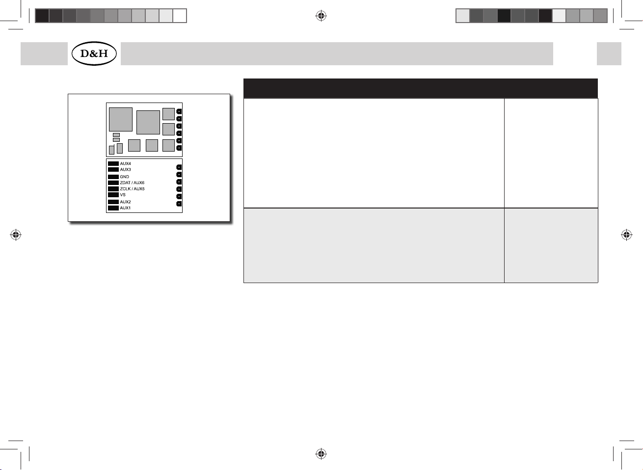
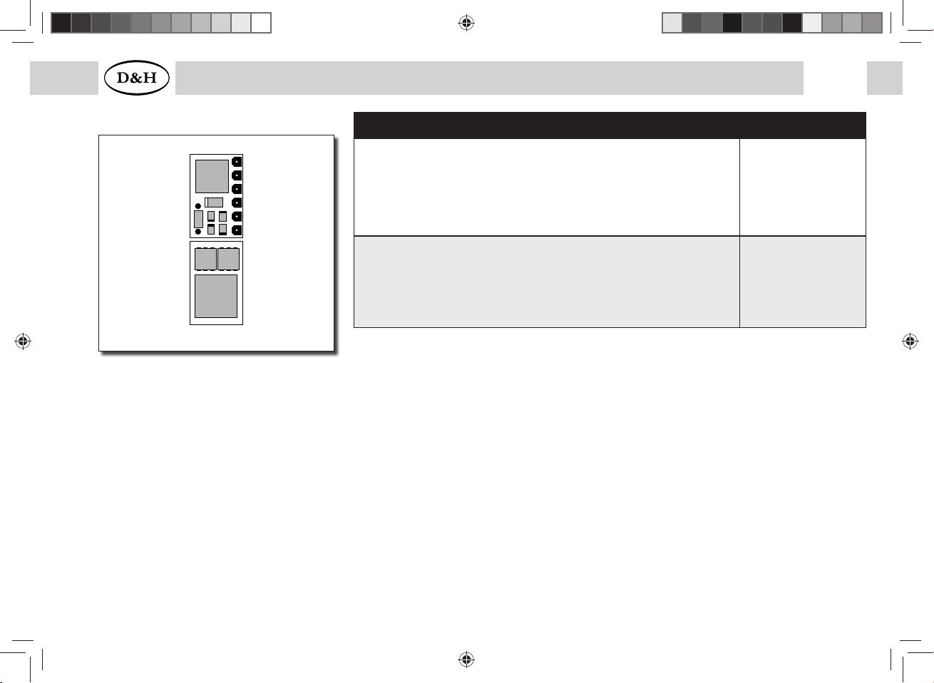
DH05C (2nd generation)
M1, M2..............Motor connection 1, 2
G1, G2...............Track connection 1, 2
LV, LR ................Front light, rear light (each 150 mA)
AUX1, AUX2.....Additional function 1, 2 (each 300 mA)
AUX3, AUX4.....Unamplified function 3, 4 *)
VS......................Supply voltage (also for SUSI)
ZCLK/AUX5......SUSI clock (or AUX5 unamplified) *)
ZDAT/AUX6......SUSI data (or AUX6 unamplified) *)
GND ..................Ground (0 V)
If necessary: Connect blue wire (common return conductor) to VS.
You can connect a buffer capacitor to VS (+) and GND (-).
Specifications DH05C
Dimensions [mm]
Total load
Maximum motor current
Maximum operating voltage
Function outputs for light: LV, LR (dimmable)
Function outputs: AUX1, AUX2 (dimmable)
Function outputs: AUX3, AUX4, AUX5, AUX6
With SUSI interface (if AUX5/AUX6 deactivated)
after publication
0,5 A
0,5 A
30 V
each 150 mA
each 300 mA
unamplified *)
X
Connecting options
Without connection wires
With connection wires
DH05C-0
DH05C-3
*) Unamplified function outputs: See supplement 3.
5 Locomotive decoder
BA DH engl FW3_12 Druck.indd 6BA DH engl FW3_12 Druck.indd 6 10.05.21 14:2610.05.21 14:26
7
Fahrzeug-/Funktionsdecoder ab Firmware-Version 1.11 7
Locomotive/Locomotive function decoder from firmware version 3.12
Specifications DH10C
Dimensions [mm]
Total load
Maximum motor current
Maximum operating voltage
Function outputs for light: LV, LR (dimmable)
Function outputs: AUX1, AUX2 (dimmable)
Function outputs: AUX3, AUX4
Function outputs: AUX5, AUX6
With SUSI interface (if AUX5/AUX6 deactivated)
12,7 x 8,9 x 1,4
1,5 A
1,5 A
30 V
each 150 mA
each 300 mA
each 1,0 A
unamplified *)
X
Connecting options
Without connection wires
With ribbon cable for interface per NEM651
With connection cable for interface per NEM651
With connection wires
6 pin connector for direct plugging (NEM651)
DH10C-0
DH10C-1
DH10C-2
DH10C-3
DH10C-4
*) Unamplified function outputs: See supplement 3.
M1
M2
G1
G2
LV
LR
DH10C (2nd generation)
M1, M2.............. Motor connection 1, 2
G1, G2............... Track connection 1, 2
LV, LR ................ Front light, rear light (each 150 mA)
AUX1, AUX2..... Additional function 1, 2 (each 300 mA)
AUX3, AUX4..... Unamplified function 3, 4 (each 1,0 A)
VS...................... Supply voltage (also for SUSI)
ZCLK/AUX5...... SUSI clock (or AUX5 unamplified) *)
ZDAT/AUX6...... SUSI data (or AUX6 unamplified) *)
GND .................. Ground (0 V)
If necessary: Connect blue wire (common return conductor) to VS.
You can connect a buffer capacitor to VS (+) and GND (-).
BA DH engl FW3_12 Druck.indd 7BA DH engl FW3_12 Druck.indd 7 10.05.21 14:2610.05.21 14:26

8Fahrzeug-/Funktionsdecoder ab Firmware-Version 1.11
8Locomotive/Locomotive function decoder from firmware version 3.12
1
14
DH14B Specifications DH14B
Dimensions [mm]
Total load
Maximum motor current
Maximum operating voltage
Function outputs for light: LV, LR (dimmable)
Function outputs: AUX1, AUX2 (dimmable)
Function outputs: AUX3, AUX4
With SUSI interface (if AUX3/AUX4 deactivated)
18,5 x 9,2 x 1,7
1,0 A
1,0 A
30 V
each 150 mA
each 300 mA
unamplified *)
X
Connecting options
14 pole foil plug for direct plugging (mTc14) DH14B
*) Unamplified function outputs: See supplement 3.
mTc14 interface
1
2
3
4
5
6
7
8
9
10
11
12
13
14
G2
G2
LV
AUX2
ZDAT
GND
M2
M1
GND
ZCLK
AUX1
LR
G1
G1
M1, M2..............Motor connection 1, 2
G1, G2...............Track connection 1, 2
LV, LR ................Front light, rear light (each 150 mA)
AUX1, AUX2.....Additional function 1, 2 (each 300 mA)
ZCLK..................SUSI clock (or AUX3 unamplified) *)
ZDAT .................SUSI data (or AUX4 unamplified) *)
GND ..................Ground (0 V)
There is no connection possibility (VS) for the common return conductor (blue wire) or a buffer capacitor.
BA DH engl FW3_12 Druck.indd 8BA DH engl FW3_12 Druck.indd 8 10.05.21 14:2610.05.21 14:26

9
Fahrzeug-/Funktionsdecoder ab Firmware-Version 1.11 9
Locomotive/Locomotive function decoder from firmware version 3.12
DH16A (2nd generation)
PluX16 interface
1 2
3 4
5 6
7 8
9 10
11 12
13 14
15 16
17 18
19 20
21 22
ZCLK
GND
LV
VS
Index
LR
--
--
ZDAT
ZVS
M1
M2
G1
G2
AUX1
AUX2
M1, M2..............Motor connection 1, 2
G1, G2...............Track connection 1, 2
LV, LR ................Front light, rear light (each 150 mA)
AUX1, AUX2.....Additional function 1, 2 (each 300 mA)
AUX3, AUX4.....Additional function 3, 4 (each 1,0 A)
VS......................Supply voltage
ZVS ...................SUSI supply voltage
ZCLK..................SUSI clock (or AUX5 unamplified) *)
ZDAT .................SUSI data (or AUX6 unamplified) *)
GND ..................Ground (0 V)
If necessary: Connect blue wire (common return conductor) to VS.
You can connect a buffer capacitor to ZVS (+) and GND (-).
Specifications DH16A
Dimensions [mm]
Total load
Maximum motor current
Maximum operating voltage
Function outputs for light: LV, LR (dimmable)
Function outputs: AUX1, AUX2 (dimmable)
Function outputs: AUX3, AUX4
Function outputs: AUX5, AUX6
With SUSI interface (if AUX5/AUX6 deactivated
after publication
1,5 A
1,5 A
30 V
each 150 mA
each 300 mA
each 1,0 A
unamplified *)
X
Connecting options
Without connection wires
With connection cable for interface per NEM652
With connection wires
16 pin connector for direct plugging (PluX16)
DH16A-0
DH16A-2
DH16A-3
DH16A-4
*) Unamplified function outputs: See supplement 3.
BA DH engl FW3_12 Druck.indd 9BA DH engl FW3_12 Druck.indd 9 10.05.21 14:2610.05.21 14:26

10 Fahrzeug-/Funktionsdecoder ab Firmware-Version 1.11
10 Locomotive/Locomotive function decoder from firmware version 3.12
DH18A (2nd generation)
Next18 interface
1 18
2 17
3 16
4 15
5 14
6 13
7 12
8 11
9 10
G1
M1
AUX1
ZCLK
GND
VS
*) AUX6
LV
G2
G1
LR
AUX5 *)
VS
GND
ZDAT
AUX2
M2
G2
Specifications DH18A
Dimensions [mm]
Total load
Maximum motor current
Maximum operating voltage
Function outputs for light: LV, LR (dimmable)
Function outputs: AUX1, AUX2 (dimmable)
Function outputs: AUX3, AUX4, AUX5, AUX6
With SUSI interface (if AUX3/AUX4 deactivated)
9,7 x 8,9 x 2,8
1,5 A
1,5 A
30 V
each 150 mA
each 300 mA
unamplified *)
X
Connecting options
18 pin connector for direct plugging (Next18) DH18A
*) Unamplified function outputs: See supplement 3.
M1, M2...............Motor connection 1, 2
G1, G2................Track connection 1, 2
LV, LR .................Front light, rear light (each 150 mA)
AUX1, AUX2......Additional function 1, 2 (each 300 mA)
AUX5, AUX6......Unamplified function 5, 6 *)
VS.......................Supply voltage (also for SUSI)
ZCLK...................SUSI clock (or AUX3 unamplified) *)
ZDAT ..................SUSI data (or AUX4 unamplified) *)
GND ...................Ground (0 V)
If necessary: Connect blue wire (common return conductor) to VS.
You can connect a buffer capacitor to VS (+) and GND (-).
1
2
3
4
5
6
7
8
910
11
12
13
14
15
16
17
18
BA DH engl FW3_12 Druck.indd 10BA DH engl FW3_12 Druck.indd 10 10.05.21 14:2610.05.21 14:26

11
Fahrzeug-/Funktionsdecoder ab Firmware-Version 1.11 11
Locomotive/Locomotive function decoder from firmware version 3.12
GND
ZDAT
ZCLK
ZVS
DH21A (2nd generation) Specifications DH21A-0/2/3/4 DH21A-5
Dimensions [mm]
Total load
Maximum motor current
Maximum operating voltage
Switching voltage at AC analog:
Max. 45 V peak = 30 V eff.
Function outputs for light: LV, LR
(dimmable)
Function outputs: AUX1, AUX2
(dimmable)
Function outputs: AUX3, AUX4
Function outputs: AUX5, AUX6
With SUSI interface
(if AUX5/AUX6 deactivated)
20,7 x 15,8 x 5,2
2,0 A
2,0 A
30 V
X
each 150 mA
each 300 mA
each 1,0 A
unamplified *)
X
20,7 x 15,8 x 5,2
2,0 A
2,0 A
30 V
X
each 150 mA
each 300 mA
unamplified *)
unamplified *)
X
Connecting options
Without connection wire
With connection cable for
interface per NEM652
With connection wires
21 pin socket board for
direct plugging (mTc21)
DH21A-0
DH21A-2
DH21A-3
DH21A-4 DH21A-5
*) Unamplified function outputs: See supplement 3.
BA DH engl FW3_12 Druck.indd 11BA DH engl FW3_12 Druck.indd 11 10.05.21 14:2610.05.21 14:26

12
Fahrzeug-/Funktionsdecoder ab Firmware-Version 1.11
12
Locomotive/Locomotive function decoder from firmware version 3.12
DH21A (2nd generation)
21 pin interface
1 22
2 21
3 20
4 19
5 18
6 17
7 16
8 15
9 14
10 13
11 12
GPIO
--
--
AUX4
ZCLK
ZDAT
LR
LV
--
--
Index
G1
G2
GND
M1
M2
--
VS
AUX1
AUX2
AUX3
VCC
M1, M2.............. Motor connection 1, 2
G1, G2............... Track connection 1, 2
LV, LR ................ Front light, rear light (each 150 mA)
AUX1, AUX2..... Additional function 1, 2 (each 300 mA)
AUX3, AUX4..... Additional function 3, 4 †)
VS...................... Supply voltage
ZVS ................... SUSI supply voltage
ZCLK.................. SUSI clock (or AUX5 unamplified) *)
ZDAT ................. SUSI data (or AUX6 unamplified) *)
GND .................. Ground (0 V)
GPIO.................. General input / output (max. +5 V / max. 3 mA)
VCC ................... +5 V / max. 15 mA
*) Unamplified function outputs: See supplement 3.
†) The DH21A existists in two different hardware variants:
– Function outputs AUX3, AUX4: each 1,0 A (connecting option -0/-2/-3/-4)
– Function outputs AUX3, AUX4: unamplified *) (connecting option -5)
If necessary: Connect blue wire (common return conductor) to VS.
You can connect a buffer capacitor to ZVS (+) and GND (-).
BA DH engl FW3_12 Druck.indd 12BA DH engl FW3_12 Druck.indd 12 10.05.21 14:2610.05.21 14:26

13
Fahrzeug-/Funktionsdecoder ab Firmware-Version 1.11 13
Locomotive/Locomotive function decoder from firmware version 3.12
2
4
6
8
10
12
14
16
18
20
22
1
3
5
7
9
12
13
15
17
19
21
DH22A (2nd generation) Specifications DH22A
Dimensions [mm]
Total load
Maximum motor current
Maximum operating voltage
Switching voltage at AC analog:
Max. 45 V peak = 30 V eff.
Function outputs for light: LV, LR (dimmable)
Function outputs: AUX1, AUX2 (dimmable)
Function outputs: AUX3, AUX4
Function outputs: AUX5, AUX6
With SUSI interface (if AUX5/AUX6 deactivated)
20,7 x 15,8 x 5,2
2,0 A
2,0 A
30 V
X
each 150 mA
each 300 mA
each 1,0 A
unamplified *)
X
Connecting options
22 pin connector for direct plugging (PluX22) DH22A-4
*) Unamplified function outputs: See supplement 3.
BA DH engl FW3_12 Druck.indd 13BA DH engl FW3_12 Druck.indd 13 10.05.21 14:2610.05.21 14:26

14
Fahrzeug-/Funktionsdecoder ab Firmware-Version 1.11
14
Locomotive/Locomotive function decoder from firmware version 3.12
DH22A (2nd generation)
PluX22 interface
1 2
3 4
5 6
7 8
9 10
11 12
13 14
15 16
17 18
19 20
21 22
GPIO
ZCLK
GND
LV
VS
Index
LR
--
--
AUX4
–
AUX3
ZDAT
ZVS
M1
M2
G1
G2
AUX1
AUX2
–
–
M1, M2.............. Motor connection 1, 2
G1, G2............... Track connection 1, 2
LV, LR ................ Front light, rear light (each 150 mA)
AUX1, AUX2..... Additional function 1, 2 (each 300 mA)
AUX3, AUX4.....Unamplified function 3, 4 (each 1,0 A)
VS...................... Supply voltage
ZVS ................... SUSI supply voltage
ZCLK.................. SUSI clock (or AUX5 unamplified) *)
ZDAT ................. SUSI data (or AUX6 unamplified) *)
GND .................. Ground (0 V)
GPIO.................. General input / output (max. +5 V / max. 3 mA)
*) Unamplified function outputs: See supplement 3.
If necessary: Connect blue wire (common return conductor) to VS.
You can connect a buffer capacitor to ZVS (+) and GND (-).
BA DH engl FW3_12 Druck.indd 14BA DH engl FW3_12 Druck.indd 14 10.05.21 14:2610.05.21 14:26
15
Fahrzeug-/Funktionsdecoder ab Firmware-Version 1.11 15
Locomotive/Locomotive function decoder from firmware version 3.12
Specifications PD05A
Dimensions [mm]
Total load
Maximum motor current
Maximum operating voltage
Function outputs for light: LV, LR (dimmable)
5,2 x 8,0 x 2,5
0,5 A
0,5 A
30 V
each 150 mA
Connecting options
Without connection wires
With ribbon cable for interface per NEM651
With connection wires
6 pin connector for direct plugging (NEM651)
PD05A-0
PD05A-1
PD05A-3
PD05A-4
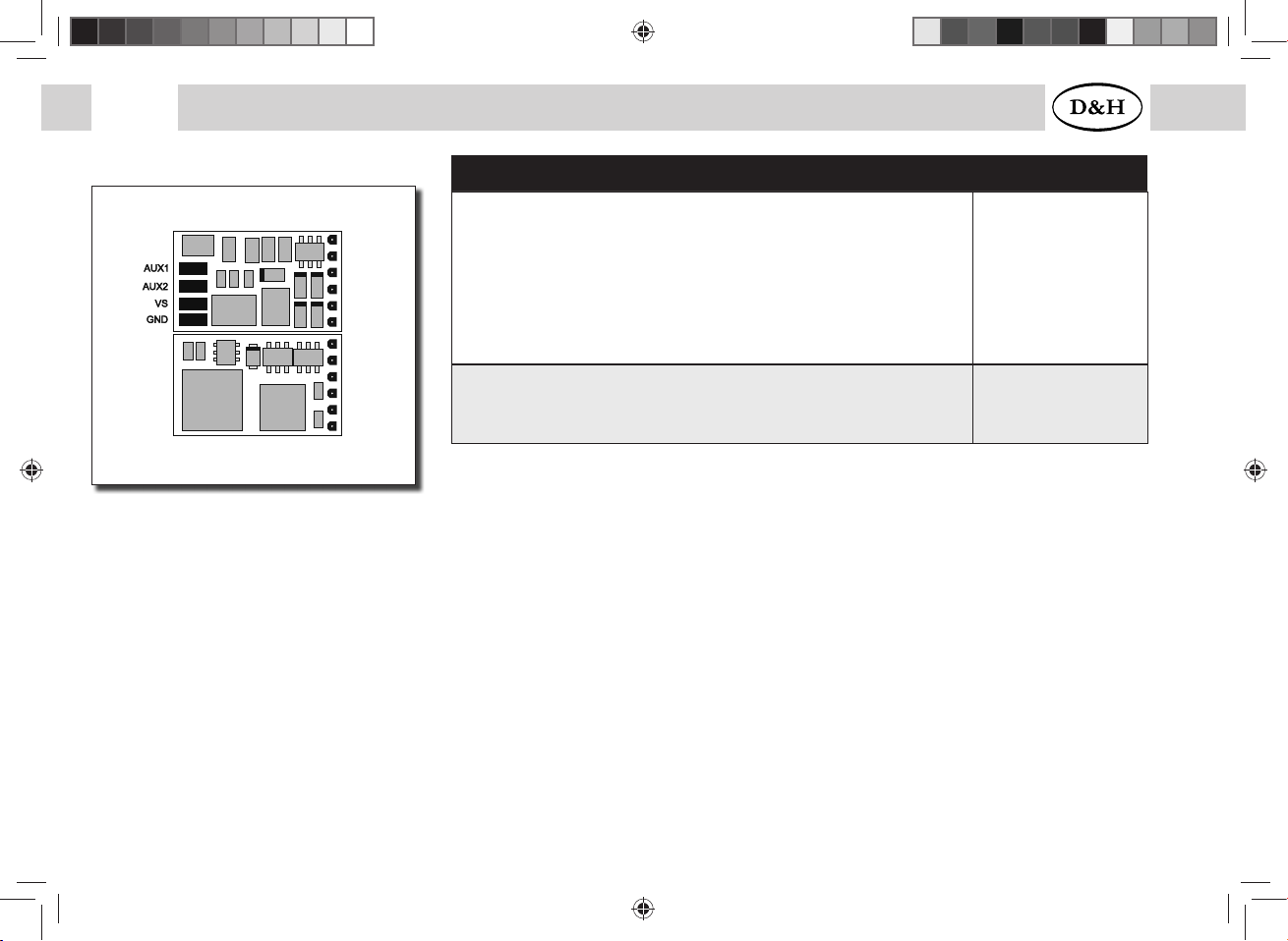
M1, M2..............Motor connection 1, 2
G1, G2...............Track connection 1, 2
LV, LR ................Front light, rear light (each 150 mA)
VS......................Supply voltage
GND ..................Ground (0 V)
If necessary: Connect blue wire (common return conductor) to VS.
You can connect a buffer capacitor to VS (+) and GND (-).
PD05A (2nd generation)
M1
M2
G1
G2
LV
LR
GND
VS
BA DH engl FW3_12 Druck.indd 15BA DH engl FW3_12 Druck.indd 15 10.05.21 14:2610.05.21 14:26
16 Fahrzeug-/Funktionsdecoder ab Firmware-Version 1.11
16 Locomotive/Locomotive function decoder from firmware version 3.12
Specifications PD06A
Dimensions [mm]
Total load
Motor voltage
Maximum motor current
Maximum operating voltage
Function outputs for light: LV, LR (dimmable)
Function outputs: AUX1, AUX2 (dimmable)
6,8 x 11,4 x 2,8
0,5 A
6 V
0,2 A
18 V
each 150 mA
each 300 mA
Connecting options
Without connection wires
With connection wires
PD06A-0
PD06A-3
M2
G2
M1
G1
LV
LR
PD06A
M1, M2..............Motor connection 1, 2
G1, G2...............Track connection 1, 2
LV, LR ................Front light, rear light (each 150 mA)
AUX1, AUX2.....Additional function 1, 2 (each 300 mA)
VS......................Supply voltage
GND ..................Ground (0 V)
If necessary: Connect blue wire (common return conductor) to VS.
You can connect a buffer capacitor to VS (+) and GND (-).
BA DH engl FW3_12 Druck.indd 16BA DH engl FW3_12 Druck.indd 16 10.05.21 14:2610.05.21 14:26

17
Fahrzeug-/Funktionsdecoder ab Firmware-Version 1.11 17
Locomotive/Locomotive function decoder from firmware version 3.12
Specifications PD12A
Dimensions [mm]
Total load
Maximum motor current
Maximum operating voltage
Function outputs for light: LV, LR (dimmable)
Function outputs: AUX1, AUX2 (dimmable)
24,2 x 11,0 x 2,4
1,0 A
1,0 A
30 V
each 150 mA
each 300 mA
Connecting options
Without connection wires
With connection cable for interface per NEM652
With connection wires
12 pin connector for direct plugging (PluX12)
PD12A-0
PD12A-2
PD12A-3
PD12A-4
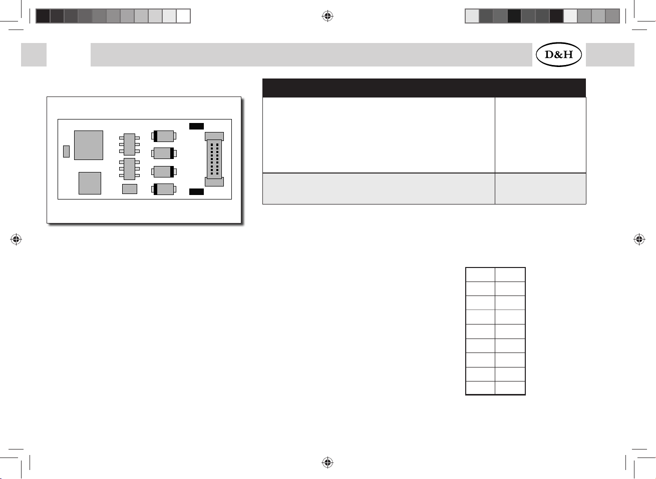
PD12A
PluX12-Interface
1 2
3 4
5 6
7 8
9 10
11 12
13 14
15 16
17 18
19 20
21 22
LV
VS
Index
LR
--
--
M1
M2
G1
G2
AUX1
AUX2
M1, M2..............Motor connection 1, 2
G1, G2...............Track connection 1, 2
LV, LR ................Front light, rear light (each 150 mA)
AUX1, AUX2.....Additional function 1, 2 (each 300 mA)
VS......................Supply voltage
GND ..................Ground (0 V)
If necessary: Connect blue wire (common return conductor) to VS.
You can connect a buffer capacitor to VS (+) and GND (-).
BA DH engl FW3_12 Druck.indd 17BA DH engl FW3_12 Druck.indd 17 10.05.21 14:2710.05.21 14:27
18 Fahrzeug-/Funktionsdecoder ab Firmware-Version 1.11
18 Locomotive/Locomotive function decoder from firmware version 3.12
Specifications PD18A
Dimensions [mm]
Total load
Maximum motor current
Maximum operating voltage
Function outputs for light: LV, LR (dimmable)
Function outputs: AUX1, AUX2 (dimmable)
23,8 x 10,8 x 2,0
1,0 A
1,0 A
30 V
je 150 mA
je 300 mA
Connecting options
18 pin connector for direct plugging (Next18) PD18A
Next18 interface
1 18
2 17
3 16
4 15
5 14
6 13
7 12
8 11
9 10
G1
M1
AUX1
–
GND
VS
–
LV
G2
G1
LR
–
VS
GND
–
AUX2
M2
G2
M1, M2..............Motor connection 1, 2
G1, G2...............Track connection 1, 2
LV, LR ................Front light, rear light (each 150 mA)
AUX1, AUX2.....Additional function 1, 2 (each 300 mA)
VS......................Supply voltage
GND ..................Ground (0 V)
If necessary: Connect blue wire (common return conductor) to VS.
You can connect a buffer capacitor to VS (+) and GND (-).
1
2
3
4
5
6
7
8
9
10
11
12
13
14
15
16
17
18
GND
VS
PD18A
BA DH engl FW3_12 Druck.indd 18BA DH engl FW3_12 Druck.indd 18 10.05.21 14:2710.05.21 14:27

19
Fahrzeug-/Funktionsdecoder ab Firmware-Version 1.11 19
Locomotive/Locomotive function decoder from firmware version 3.12
PD21A Specifications PD21A
Dimensions [mm]
Total load
Maximum motor current
Maximum operating voltage
Function outputs for light: LV, LR (dimmable)
21,2 x 15,5 x 2,9
1 A
1 A
30 V
each 150 mA
Connecting options
21 pin socket board for direct plugging (mTc21) PD21A-4
21 pin interface
1 22
2 21
3 20
4 19
5 18
6 17
7 16
8 15
9 14
10 13
11 12
–
--
--
–
–
–
LR
LV
--
--
Index
G1
G2
GND
M1
M2
--
VS
AUX1
AUX2
–
–
M1, M2..............Motor connection 1, 2
G1, G2...............Track connection 1, 2
LV, LR ................Front light, rear light (each 150 mA)
AUX1, AUX2.....Additional function 1, 2 (each 300 mA)
VS......................Supply voltage
GND ..................Ground (0 V)
If necessary: Connect blue wire (common return conductor) to VS.
You can connect a buffer capacitor to VS (+) and GND (-).
BA DH engl FW3_12 Druck.indd 19BA DH engl FW3_12 Druck.indd 19 10.05.21 14:2710.05.21 14:27
20
Fahrzeug-/Funktionsdecoder ab Firmware-Version 1.11
20
Locomotive/Locomotive function decoder from firmware version 3.12
5.1 Functions
• Operation can be controlled either by conventional DC command stations or by digital central units supporting the
formats SelecTRIX 1 and 2, NMRA standard (DCC) or MM1/MM2 standard
• Automatic switch over from conventional DC to digital operation
• In case of digital operation the last programmed system will be activated. Automatic switching into a certain
operating mode is not possible because of the multiprotocol operation. For switching a parameter (e.g. locomotive
address) is to be readout and must be written again in the required operating mode. Thus the switching to the
required track protocol is completed.
• SelecTRIX 1..... 31 speed steps, 100 addresses
• SelecTRIX 2..... 127 speed steps, 10.000 addresses, 16 additional functions
• DCC................. short addresses (1-127), long addresses (0001-9999), with 14, 28, 126 speed steps
•State of art load regulation, in this way an especially smooth control mode
• Different control variants for an optimal adaption to the motor
• 127 internal speed steps
• Adjustable motor frequency (low frequency, 16 kHz, 32 kHz)
• Block section operation by simple diodes in digital operation
• Light and function outputs are (partly) dimmable and can be activated analogously
• Shunting gear
• Motor, light and track connections electronically changeable
• All function outputs are freely programmable
• Thermal protection
• Reset function for DCC and SX2
• Updateability of the decoder
BA DH engl FW3_12 Druck.indd 20BA DH engl FW3_12 Druck.indd 20 10.05.21 14:2710.05.21 14:27
This manual suits for next models
28
Table of contents
Other D&H Media Converter manuals


