D&H SD05A User manual

Doehler & Haass
Sounddecoder
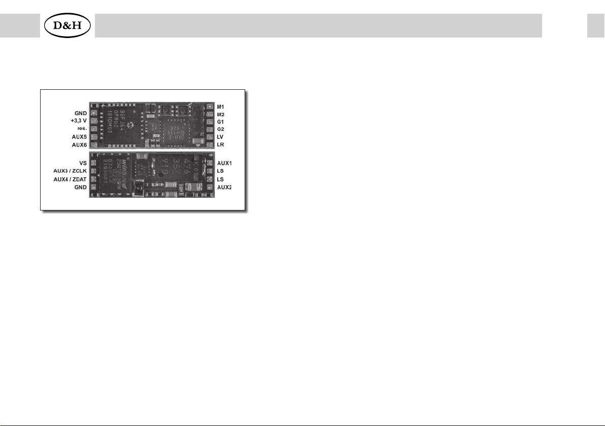
SD05A
SD10A
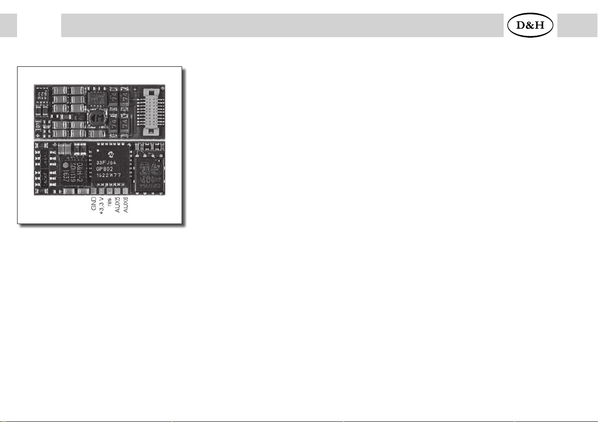
GND
+3,3 V
res.
AUX5
AUX6
AUX4
AUX3
4
6
8
10
12
14
16
18
3
5
7
9
11
13
15
17
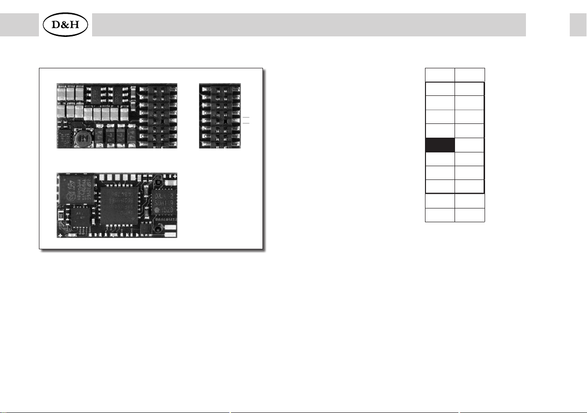
SD16A
SD18A
SD21A
SD22A

2Contents
1 Introduction ............................................................................................................................................ 4
2 Safety instructions ................................................................................................................................. 4
3 Warranty ................................................................................................................................................. 4
4 Support and help.................................................................................................................................... 4
5 Sounddecoder SD05A / SD10A / SD16A / SD18A / SD21A / SD22A ............................................... 5
5.1 Driving operation .................................................................................................................................... 15
5.2 Sound operation ..................................................................................................................................... 16
6 Installation of the sounddecoder........................................................................................................ 17
6.1 Preparation ............................................................................................................................................. 17
6.2 Installation .............................................................................................................................................. 18
6.3 Check after installation ........................................................................................................................... 19
7 Operating system SelecTRIX 1 (SX1) ................................................................................................. 20
7.1 Functions................................................................................................................................................ 20
7.2 SX1 operation by SX2 parameter programming ..................................................................................... 21
7.3 Operation................................................................................................................................................ 23
7.4 Explanation of the brake sections .......................................................................................................... 23

3
Sounddecoder from firmware version 1.12
8 Operating system DCC....................................................................................................................... 24
8.1 Functions .............................................................................................................................................. 24
8.2 Setting options ..................................................................................................................................... 25
8.2.1 List of supported CV for driving operation............................................................................................ 26
8.2.2 List of supported CV for sound operation............................................................................................. 41
8.3 Operation.............................................................................................................................................. 47
9 Operating system Märklin-Motorola (MM)...................................................................................... 48
9.1 Functions .............................................................................................................................................. 48
9.2 Programming with Märklin central unit 6020/6021............................................................................... 49
10 Operating system SelecTRIX 2 (SX2) ............................................................................................... 51
10.1 Functions .............................................................................................................................................. 51
10.2 Setting options ..................................................................................................................................... 52
10.2.1 List of supported parameters for driving operation .............................................................................. 53
10.2.2 List of supported parameters for sound operation ............................................................................... 66
10.3 Operation.............................................................................................................................................. 71
Supplement 1: Declaration for function mapping....................................................................................... 72
Supplement 2: Speed characteristics ........................................................................................................... 74
Supplement 3: Unamplified function outputs AUX3 ... AUX6: .................................................................. 75
Supplement 4: Electric couplings / freewheeling diode............................................................................. 75
Supplement 5: Automatic coupling procedure (“coupling waltz”).............................................................. 76
Supplement 6: Decoder recognition (type and firmware version) ................................................................ 80
Contents

4Sounddecoder from firmware version 1.12
1 Introduction
The sounddecoders are compatible with the protocols of SelecTRIX standard SX1 and SX2 as well as with NMRA-DCC and
MM1/MM2 standard. They and can be operated by every central unit supporting one of these data formats. They can be
used for normal direct current motors as well as for coreless motors.
Operation on alternating current layouts with switching impulse is not allowed!
The switching impulse destroys the decoder!
Exception: SD21A and SD22A
2 Safety instructions
This product is not suitable for children under 14 years.
It might be swallowed by children under 3 years!
An improper use involves a risk of injury due to sharp edges and points!
3 Warranty
Every sounddecoder is fully tested before delivery. Should nevertheless a failure occur please contact the dealer where
you purchased the decoder or directly the producer (Doehler & Haass enterprises). The warranty period is 24 month from
the date of purchase.
4 Support and help
In case you have any problems please contact us by email: technik@doehler-haass.de
Normally you would get an answer within a few days.
5
Sounddecoder from firmware version 1.12 5
Sounddecoder from firmware version 1.12
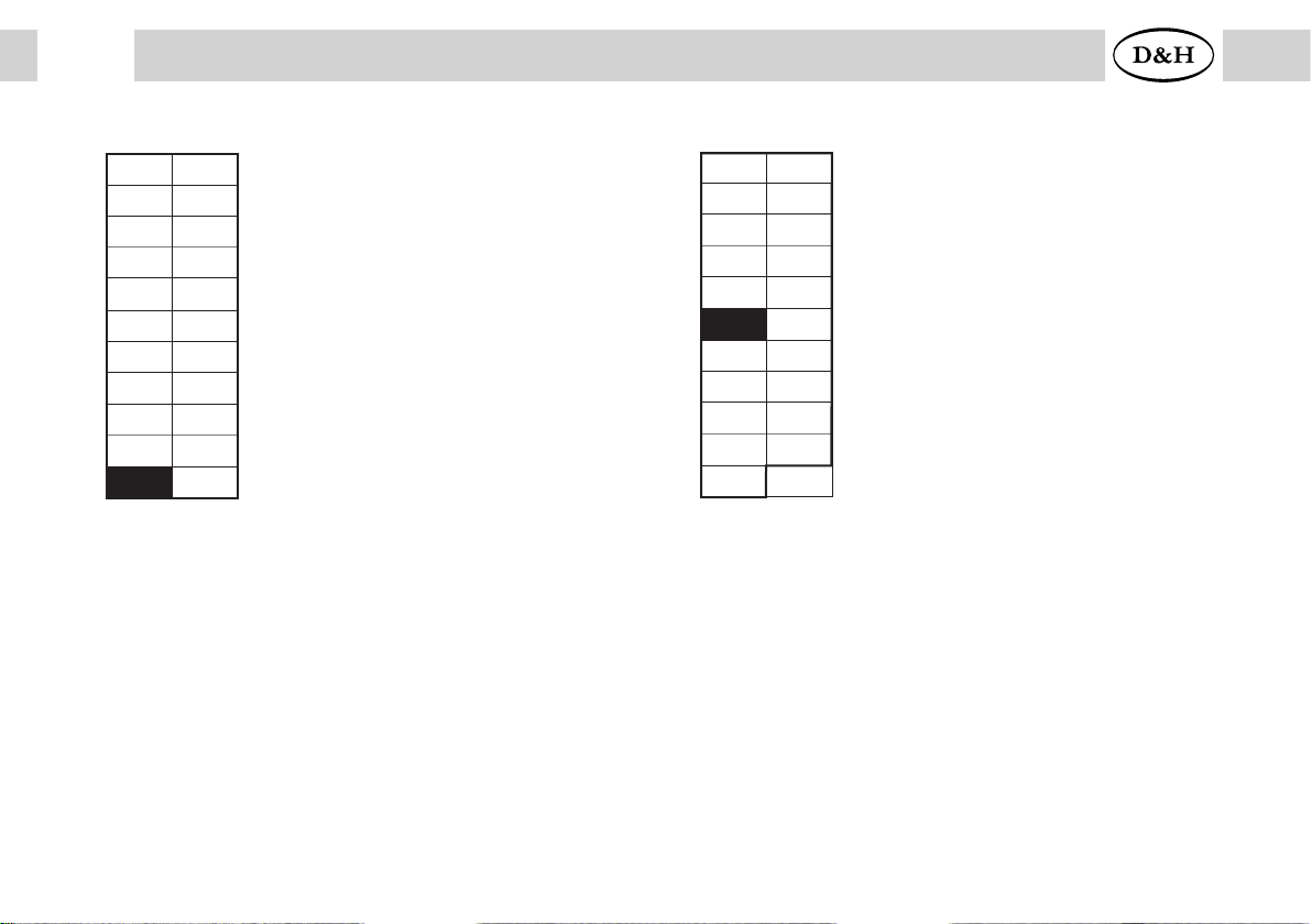
VS Supply voltage (also for SUSI)
If necessary: Blue wire
(common return conductor) to VS
ZCLK SUSI clock
(or AUX3 unamplified or AUX5 unamplified) *)
ZDATSUSI data
(or AUX4 unamplified or AUX6 unamplified) *)
GND SUSI ground
*) Unamplified function outputs: see supplement 3
M1, M2 Motor connection 1, 2
G1, G2 Track connection 1, 2
LV Front light
LR Rear light
AUX1, AUX2 Additional function 1, 2
AUX3, AUX4 Unamplified additional function 3, 4 *)
AUX5, AUX6 Unamplified additional function 5, 6 *)
LS Speaker
GND Ground
+3,3 V Electronic supply voltage
(not for the user!)
res.Please do not connect anything!
5 Sounddecoder SD05A / SD10A / SD16A / SD18A / SD21A / SD22A
SD05A

6Sounddecoder from firmware version 1.12
6Sounddecoder from firmware version 1.12
VS Supply voltage (also for SUSI)
If necessary: Blue wire
(common return conductor) to VS
ZCLK SUSI clock
(or AUX3 unamplified or AUX5 unamplified) *)
ZDATSUSI data
(or AUX4 unamplified or AUX6 unamplified) *)
GND SUSI ground
*) Unamplified function outputs: see supplement 3
M1, M2 Motor connection 1, 2
G1, G2 Track connection 1, 2
LV Front light
LR Rear light
AUX1, AUX2 Additional function 1, 2
AUX3, AUX4 Unamplified additional function 3, 4 *)
AUX5, AUX6 Unamplified additional function 5, 6 *)
LS Speaker
GND Ground
+3,3 V Electronic supply voltage
(not for the user!)
res.Please do not connect anything!
SD10A
7
Sounddecoder from firmware version 1.12
7
Sounddecoder from firmware version 1.12
AUX3, AUX4 Additional function 3, 4
AUX5, AUX6 Unamplified additional function 5, 6 *)
GND Ground
+3,3 V Electronic supply voltage (not for the user!)
res.Please do not connect anything!
*) Unamplified function outputs: see supplement 3
1 2
3 4
5 6
7 8
9 10
11 12
13 14
15 16
17 18
19 20
21 22
GPIO
ZCLK
GND
LV
VS
Index
LR
LS
LS
AUX4
AUX6
AUX3
ZDAT
VS
M1
M2
G1
G2
AUX1
AUX2
AUX5
AUX7
GND
+3,3 V
res.
AUX5
AUX6
AUX4
AUX3
4
6
8
10
12
14
16
18
3
5
7
9
11
13
15
17
SD16A
8Sounddecoder from firmware version 1.12
8Sounddecoder from firmware version 1.12
AUX5, AUX6 Unamplified additional function 5, 6 *)
GND Ground
+3,3 V Electronic supply voltage (not for the user!)
res.Please do not connect anything!
*) Unamplified function outputs: see supplement 3
SD18A
9
Sounddecoder from firmware version 1.12
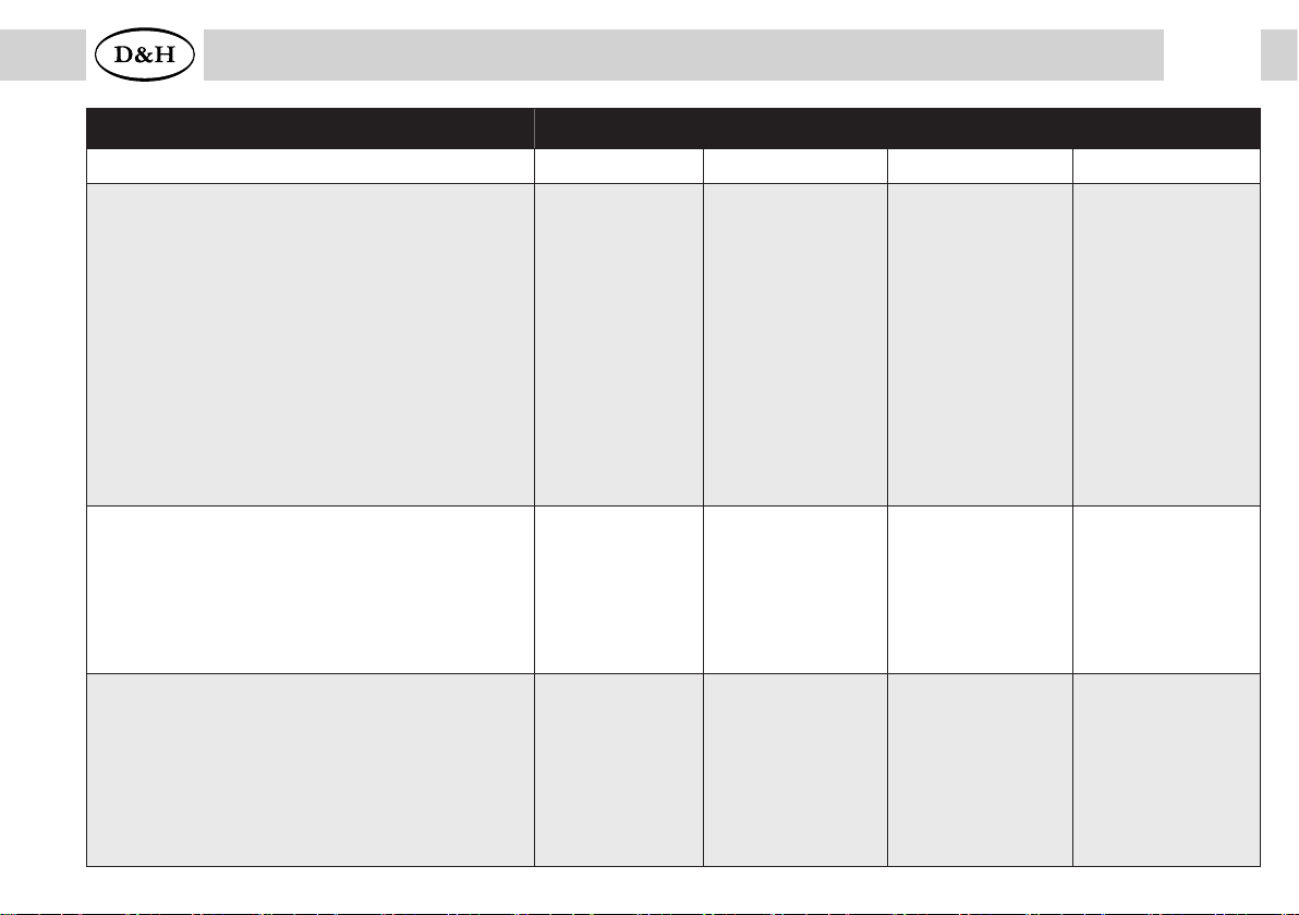
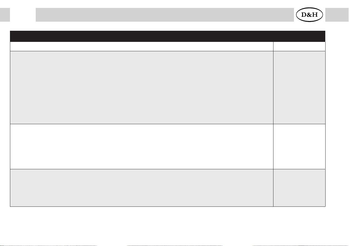
Specifications SD05A SD10A SD16A SD18A
Dimensions [mm] 20,0 x 7,6 x 3,0 21,2 x 9,1 x 3,4 20,2 x 10,5 x 3,0 21,4 x 9,0 x 3,2
Driving characteristic values
Operating mode SX1, SX2, DCC, MM, DC analog
Total load
Maximum motor current
Maximum operating voltage
2 Light outputs: LV, LR (dimmable)
2 Additional outputs: AUX1, AUX2 (dimmable)
2 Additional outputs: AUX3, AUX4
2 Additional outputs: AUX5, AUX6
SUSI interface
0,5 A
0,5 A
18 V
each 150 mA
each 150 mA
unamplified
unamplified
available
(if AUX3/AUX4
deactivated)
1,0 A
1,0 A
30 V
each 150 mA
each 300 mA
unamplified
unamplified
available
(if AUX3/AUX4
deactivated)
1,5 A
1,5 A
30 V
each 150 mA
each 300 mA
each 1,0 A
unamplified
available
1,0 A
1,0 A
30 V
each 150 mA
each 300 mA
unamplified
unamplified
available
(if AUX3/AUX4
deactivated)
Sound characteristic values
Sampling rate
Independent sound channels
Memory size
Memory period
Maximum output rating
22 kHz
8
128 Megabits
up to 760 s
1,6 W (8 Ω)
22 kHz
8
128 Megabits
up to 760 s
2,6/1,6 W (4/8 Ω)
22 kHz
8
128 Megabits
up to 760 s
2,6/1,6 W (4/8 Ω)
22 kHz
8
128 Megabits
up to 760 s
2,6/1,6 W (4/8 Ω)
Connecting options
Without connection wires
With ribbon cable for standard plug NEM651
With connection cable for interface per NEM652
With connection wires
16 pin connector for direct plugging (PluX16)
18 pin connection for direct plugging (Next18)
SD05A-0
SD05A-1
SD05A-3
SD10A-0
SD10A-1
SD10A-3
SD16A-0
SD16A-2
SD16A-3
SD16A-4
SD18A

10 Sounddecoder from firmware version 1.12
10 Sounddecoder from firmware version 1.12
AUX5, AUX6 Unamplified additional function 5, 6 *) *) Unamplified function outputs: see supplement 3
ZVS SUSI supply voltage (also suitable for connecting capacitors)
GND Ground
+3,3 V Electronic supply voltage (not for the user!)
res.Please do not connect anything!
SD21A-4 SD21A-5

11
Sounddecoder from firmware version 1.12 11
Sounddecoder from firmware version 1.12
AUX5, AUX6 Unamplified additional function 5, 6 *)
ZVS SUSI supply voltage
(also suitable for connecting capacitors)
GND Ground
+3,3 V Electronic supply voltage (not for the user!)
res.Please do not connect anything!
*) Unamplified function outputs: see supplement 3
SD22A
12 Sounddecoder from firmware version 1.12
GPIO General input/output
(max. +5 V / max. 3 mA)
G1, G2 Track 1, 2
M1, M2 Motor 1, 2
LV Front light
LR Rear rückwärts
AUX1-AUX6 Additional function 1-6
LS Speaker
VCC +5 V / max. 15 mA
VS Supply voltage
ZVS SUSI supply voltage
(also suitable for connecting capacitors)
ZCLK SUSI clock (or AUX3 unamplified or
AUX5 unamplified *)
ZDAT SUSI data (or AUX4 unamplified or
AUX6 unamplified *)
GND SUSI ground
*) Unamplified function outputs: see supplement 3
PluX22 interface
1 2
3 4
5 6
7 8
9 10
11 12
13 14
15 16
17 18
19 20
21 22
GPIO
ZCLK
GND
LV
VS
Index
LR
LS
LS
AUX4
AUX6
AUX3
ZDAT
ZVS
M1
M2
G1
G2
AUX1
AUX2
AUX5
AUX7
21 pin interface
1 22
2 21
3 20
4 19
5 18
6 17
7 16
8 15
9 14
10 13
11 12
GPIO
--
AUX6
AUX4
ZCLK
ZDAT
LR
LV
LS
LS
Index
G1
G2
GND
M1
M2
AUX5
VS
AUX1
AUX2
AUX3
VCC

13
Sounddecoder from firmware version 1.12
Specifications SD21A-4 SD21A-5
Dimensions [mm] 26,6 x 15,8 x 4,0 26,6 x 15,8 x 4,0
Driving characteristic values
Operating mode SX1, SX2, DCC, MM, DC/AC analog
Total load
Maximum motor current
Maximum operating voltage
Switching voltage at AC-analog: max. 45 V peak = 30 V effective
Function outputs for light: dimmable LV, LR (dimmable)
Function outputs: AUX1, AUX2 (dimmable)
Function outputs: AUX3, AUX4, AUX5, AUX6
SUSI interface
2,0 A
2,0 A
30 V
each 150 mA
each 300 mA
each 1,0 A
available
2,0 A
2,0 A
30 V
each 150 mA
each 300 mA
unamplified
available
Sound characteristic values
Sampling rate
Independent sound channels
Memory size
Memory period
Maximum output rating
22 kHz
8
128 Megabits
up to 760 s
2,6/1,6 W (4/8 Ω)
22 kHz
8
128 Megabits
up to 760 s
2,6/1,6 W (4/8 Ω)
Connecting options
21 pin socket board for direct plugging (mTc21) SD21A-4 SD21A-5
14 Sounddecoder from firmware version 1.12
Specifications SD22A
Dimensions [mm] 26,6 x 15,8 x 4,0
Driving characteristic values
Operating mode SX1, SX2, DCC, MM, DC/AC analog
Total load
Maximum motor current
Maximum operating voltage
Switching voltage at AC-analog: max. 45 V peak = 30 V effective
Function outputs for light: LV, LR (dimmable)
Function outputs: AUX1, AUX2 (dimmable)
Function outputs: AUX3, AUX4, AUX5, AUX6
SUSI interface
2,0 A
2,0 A
30 V
each 150 mA
each 300 mA
each 1,0 A
available
Sound characteristic values
Sampling rate
Independent sound channels
Memory size
Memory period
Maximum output rating
22 kHz
8
128 Megabits
up to 760 s
2,6/1,6 W (4/8 Ω)
Connecting option
Without connection wires
With connection cable for interface per NEM652
With connection wires
22 pin socket board for direct plugging (PluX22)
SD22A-0
SD22A-2
SD22A-3
SD22A-4

15
Sounddecoder from firmware version 1.12
5.1 Driving operation
• Operation can be controlled either by conventional DC command station or by digital central units supporting the
formats SelecTRIX 1 and 2, NMRA norm (DCC) or MM1/MM2 standard
• Automatic switchover between analog and digital operation
• In case of digital operation the last programmed system will be activated. Automatic switching into a certain
operating mode is not possible because of the multiprotocol operation. For switching a parameter (e.g. locomotive
address) is to be readout and must be written again in the required operating mode. Thus the switching to the
required track protocol is completed.
• SelecTRIX 1..... 31 speed steps, 100 addresses
•SelecTRIX 2..... 127 speed steps, 10.000 addresses, 16 additional functions
•DCC................. Short addresses (1-127), long addresses (0001-9999), with 14, 28, 126 speed steps
•Load control state of the art, that way an especially smooth regulation behavior
• Various regulation variants for an optimal adaption of the motor
• 127 internal speed steps
• Adjustable motor frequency (low frequency, 16 kHz, 32 kHz)
• Block system operation with simple diodes in digital operation
•Outputs for light and function dimmable and can be activated analogously
• Shunting gear
• Electronic interchange ability for the connections of motor, light and track
• All function outputs are freely programmable
• Thermal protection
• Reset function for DCC and SX2
•Decoder can be updated (programmer is required):
Incorporated sounddecoder can be updated when the locomotive is standing on track (no need to open the engine).
SW can be downloaded from D&H homepage for free.
• Asymmetric digital voltage brakes (four diodes connected in series and one diode anti parallel),
Slow approach (with appropriate brake modules) and bidirectional communication (locomotive address feedback
signal in DCC operation, RailCom®).

16 Sounddecoder from firmware version 1.12
5.2 Sound operation
• Originally designed sound projects for steam, diesel and electric locomotives (no “standard sounds“)
• Realistic steam sound with synchronized wheel and overlapping exhaust whams. Pitch is depending on speed
steps and independent from boiling sound
•Realistic diesel-hydraulic driving sound with pitch depending on speed steps, variable coasting speed drive and
independent acceleration steps, turbocharger and dynamic brakes
•Realistic diesel-mechanic driving sound with several gears, coasting speed, several driving and acceleration steps
and possible shift sound
• Realistic electric driving sound with traction motor and traction motor fan as well as upgrading sounds (pantograph,
main switch etc.), switchgear sound and dynamic brakes
• Bell, horn, whistle, close doors etc. (according to the sound project) can be separately triggered at any time
•All sound procedures are freely configurable (“Function Mapping“) and can be accidentally triggered
•Speaker connection protected from short circuit and overload
•Low heat generation through high tech
• Loading of the sound projects by programmer over SUSI interface (about 6 minutes). For this the locomotive has to
be opened and the sounddecoder has to be connected via SUSI interface with the programmer. For that appropriate
connecting adapters may be necessary. The sound projects can be downloaded from the D&H homepage for free.

17
Sounddecoder from firmware version 1.12
6 Installation of the sounddecoder
6.1 Preparation
Check if the locomotive is in perfect condition electrically and mechanically before installation. Defects or dirt must be
eliminated first. Pay attention to the instructions of the locomotive producer.
Only locomotives running smoothely in direct current mode should be equipped with the sounddecoder. New locomotives
should be run at least 30 minutes in each driving direction.
Before installing the sounddecoder all connections between the motor and the track connections have to be removed
(sliding contact, chassis, etc.).
Both motor connections must be disconnected from the ground!
Further on all capacitors have to be removed, particularly those associated to the connections of light and motor.
For fixing the decoder we recommend a double-sided adhesive tape.
With sound decoders, always solder the speaker first.
Carry out all soldering work in a de-energized state.
Avoid test drives with stripped unsoldered cable ends.

18 Sounddecoder from firmware version 1.12
6.2 Installation
There are following variants to connect the sounddecoder:
1 In case your locomotive is equipped with a 16/22 pin PluX interface:
The SD16A-4 and the SD22A-4 can be directly inserted into the interface.
2 In case your locomotive is equipped with a 18 pin/Next18 interface:
The SD18A can be directly inserted into the interface.
3 In case your locomotive is equipped with a 21 pin/MTC21 interface:
The SD21A-4 can be directly inserted into the interface.
4 In case your locomotive is equipped with an interface corresponding to NEM 651:
TheSD05A-1ortheSD10A-1hasalreadytheappropriateconnectionsforthisplug.Shorttheribboncableuptoapproximately5
mm and remove the rest of the insulation. The decoder can be now inserted into the interface without any problems.
For SD18A a N18-K-1 adapter is required. It has already the appropriate connections for this plug. Short the rib-bon cable
up to approximately 5 mm and remove the rest of the insulation. The adapter can be now inserted into the interface
without any problems.
5 In case your locomotive is equipped with an interface corresponding to NEM 652:
For SD18A a N18-G-2 adapter is required.
For SD21A-4 a M21-2 adapter is required.
They are equipped with the appropriate connection cable for this socket. You can connect the adapter with the in-terface
without any problems.
6
If your locomotive is not equipped with an appropriate interface, the sounddecoder must be wired individually. For this
you can either use SD05A-3 or the SD10A-3 or, when using other sounddecoder, the adapter N18-K-3, N18-G-3, M21-3
and P22-3, according to the type of the sounddecoder.
7
SD05A-0 or the SD10A-0 resp. the adapter N18-K-0, N18-G-0 and M21-0 should be used only by experienced model
railroaders, as the connection wires must be soldered directly onto the adapter.
For fixing the adapter we recommend a double sided adhesive tape.

19
Sounddecoder from firmware version 1.12
For installation variant 6 connect the wires of SD05A-3, SD10A-3 or of the adapter according to the following diagram:
red wire ........................ with the right track wire
black wire ..................... with the left track wire
orange wire................... with the motor wire, which was connected with the right track wire
gray wire....................... with the motor wire, which was connected with the left track wire
white wire..................... with the front light
yellow wire ................... with the rear light
green wire .................... function output AUX1 *)
violet wire..................... function output AUX2 *)
blue wire....................... common return, up to 30 Volt (+VS) *)
*) Only N18-G-3, M21-3 and P22-3
For installation variants 4-6 connect:
brown wires.................. with the speaker
6.3 Check after installation
The first test should be executed in the programming mode (e.g. by reading out the address). In case of an incorrect
feedback (confirmation signal) to the central unit (“Error“), please check again the correct assignment of the connections,
resepectively if the motor is really disconnected from the chassis electrically.

20 Sounddecoder from firmware version 1.12
7 Operating system SelecTRIX 1 (SX1)
Attention!
The locomotive sounddecoder do not support SX1 programming.
You can adjust SX1 operation by SX2 parameter programming according the table under point 7.2.
7.1 Functions
Speed steps.................................................31
Speed steps (internal)................................127
Front light/rear light ................................... yes
Additional functions.......................................2
Functions in additional channel .....................8 (connectable with loco address + 1)
Operation with deceleration diodes........... yes
Locomotive address output....................... yes
This manual suits for next models
5
Table of contents
Other D&H Media Converter manuals


