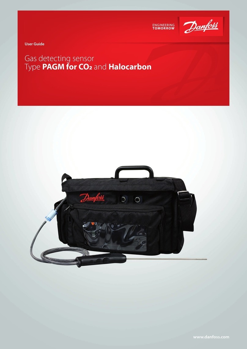
Danfoss GDC User manual

RI7HA352 © Danfoss A/S (RC-CMS / MWA), 02-2005 1
Instruction
GDA, GDC, GDHC,
GDHF, GDH
148R9527
148R9527
fig. 1
fig. 2 fig. 3
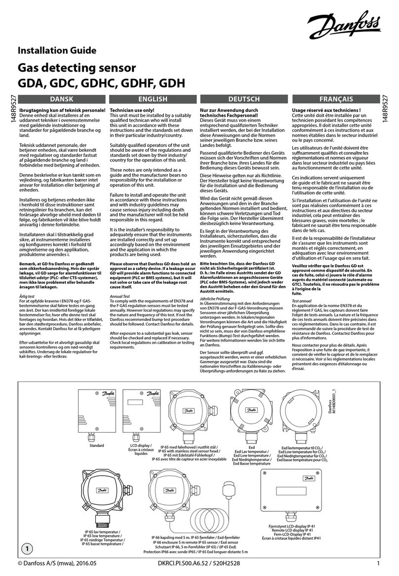
Standard
LCD display / Écran à cristaux liquides
Lav temperatur / Low temperature /
Niedrigtemperatur / Basse température
IP 65
EExd
Standard IP 65
EE xd
Detektorprintkort / Sensor PCB /
Sensorkarte / Carte de détection
Hovedprintkort / Mother PCB /
Hauptplatine / Carte mère
Detektorprintkort med ekstern detektor /
Sensor PCB with external sensor /
Sensorkarte mit externem Sensor /
Carte de détection aved détecteur externe
Hovedprintkort / Mother PCB /
Haupfplatime / Carte mère
Detektorhoved / Sensor head /
Sensorkopf / Tête de détection
Lav temperatur / Low temperature
Niedrigtemperatur / Basse température
LCD display
Écran à cristaux liquides

2 RI7HA352 © Danfoss A/S (RC-CMS / MWA), 02-2005
fig. 4
fig. 5
Tilslutning af jumper på alle modeller / Jumper connection for all models / Steckbrückenanschlüsse für alle Modelle /
Raccord cavalier pout tous modèles
Skærm/Stelforb. -
Screen/GRD -
Schirm/Erde -
Écran/Terre
Danfoss m2
Jord/Stelforb. - Earth/GRD -
Masse/Erde - Terre
{
{
{
Adresse /
Address: 12H
S3=1; S2=2
Spændingsforsyning /
Voltage supply /
Spannungsversorgung /
Tension d’alimentation
Analog udgang /
Analog output /
Analogausgang /
Sortie Analogique
Digital udgang - Højt niveau alarm NO /
Digital output - Low level alarm NO /
Digital Ausgang - Hochpegel Alarm NO /
Sortie numérique - Niveau haut alarme NO
Digital udgang - Lavt niveau alarm NO /
Digital output - High level alarm NO /
Digital Ausgang - Niedrigpegel Alarm NO /
Sortie numérique - Niveau bas alarme NO
Elektrisk tilslutning af alle modeller / Electrical connection for all models / Elektrischer Anschluss für alle Modelle /
Raccordements électriques pout tous modèles
➀
➁
➂
➃
➄
➅
➆
➇
➈➉
Ved udskiftning af jumpere skal strømmen afbrydes
(CON1) for at aktivere den nye jumperindstilling. /
If changing any jumper power must be disconnected
(CON1) to enable the new jumper setting. /
Werden Steckbrücken geändert, ist die Spannungs-
versorgung abzuschlaten (CON1) um die neue
Steckbrückeneinstellung wirksom zu machen. /
En cas de changement d’un cavalier, il est nécessaire de
couper l’alimentation (CON1) afin d’activer le réglage du
nouveau cavalier.
Gul LED3: Alarm for lavt niveau / Yellow LED3: Low alarm /
Gelbe LED3: Niedrigalarm / DEL3 jaune : Alarme basse
Rød LED2: Alarm for højt niveau / Red LED2: High alarm /
Rote LED2: Hochalarm / Del2 Rouge : Alarme haute
Grøn LED1: Anvendt spænding / Green LED1: Voltage
applied / Grüne LED1: Spannung liegt an / DEL1 verte :
Tension aux bornes
JP1: Forsinket responstid, alram for lavt niveau /
JP1: Delay response time for Low Level alarm /
JP1: Ansprechverzögerung für Niedrigpegelalarm /
JP1: Temps de résponse avec délai pour alrame de
niveau bas
JP2: Forsinket responstid, alarm for højt niveau /
JP2: Delay response time for High Level alarm /
JP2: Ansprechverzögerung für Hochpegelalarm /
JP2: Temps de résponse avec délai pour alarme de
niveau haut
Indstilling af digital udgang, alarm for højt niveau
Setting for digital output, High Level alarm /
Einstellung für Digitalausgang, Hochpegelalarm /
Réglage de la sortie numérique, Alarme de niveau haut
Indstilling af digital udgang, alarm for lavt niveau /
Settings for digital output, Low Level alarm /
Einstellung für Digitalausgang, Niedrigpegelalarm /
Réglage de la sortie numérique, Alarme de niveau bas
JP7: Alarm for højt niveau / JP7: High Level alarm /
JP7: Hochpegelalarm / JP7: Alarme de niveau haut
JP8: Alarm for lavt niveau / JP8: Low Level alarm /
JP8: Niedrigpegelalarm / JP8: Alarme de niveau bas
Manuel nulstilling af alarm for lavt/højt niveau /
Manual reset of Low/High Level alarm /
Manuelle Rückstellung von Niedrig-/Hochpegelalarm /
Réinitialisation manuelle de l’alarme de niveau bas-haut
–/0V
+12-30V d.c./12-24 V a.c.
0V
4-20 mA
0-10V
0-5V

RI7HA352 © Danfoss A/S (RC-CMS / MWA), 02-2005 3
fig. 7
fig. 6
Justering af lave/høje alarmværdier / Adjusting low/high alarm values / Einstellen der Niedrig-/Hochwerte /
Réglage des valeurs d’alarme basse-haute
Indstilling af adresse ved kommunikation med Danfoss m2 / Setting of address when communicating to Danfoss m2 /
Einstellen der Adresse zur Kommunikation mit Danfoss m2 / Réglage d’adresse pour communication avec Danfoss m2
Maks. 31 GD-detektorer
Max. 31 pcs GD
Max. 31 stck. GD
Maxi : 31 unités GD
Maks. 1000 m (1,094 yards)
Max. 1000 m (1.094 yards)
Maxi : 1000 m (1,094 yards)
(Skærm)
(Screen)
(Schirm)
(Écran)

4 RI7HA352 © Danfoss A/S (RC-CMS / MWA), 02-2005
fig. 8
Kanal på Danfoss m2 /
Channel on Danfoss m2 /
Kanal von Danfoss m2 /
Canal zur Danfoss m2 S3 S2
Kanal på Danfoss m2 /
Channel on Danfoss m2 /
Kanal von Danfoss m2 /
Canal zur Danfoss m2 S3 S2
Kanal på Danfoss m2 /
Channel on Danfoss m2 /
Kanal von Danfoss m2 /
Canal zur Danfoss m2 S3 S2
1 0 1 34 2 2 67 4 3
2 0 2 35 2 3 68 4 4
3 0 3 36 2 4 69 4 5
4 0 4 37 2 5 70 4 6
5 0 5 38 2 6 71 4 7
6 0 6 39 2 7 72 4 8
7 0 7 40 2 8 73 4 9
8 0 8 41 2 9 74 4 A
9 0 9 42 2 A 75 4 B
10 0 A 43 2 B 76 4 C
11 0 B 44 2 C 77 4 D
12 0 C 45 2 D 78 4 E
13 0 D 46 2 E 79 4 F
14 0 E 47 2 F 80 5 0
15 0 F 48 3 0 81 5 1
16 1 0 49 3 1 82 5 2
17 1 1 50 3 2 83 5 3
18 1 2 51 3 3 84 5 4
19 1 3 52 3 4 85 5 5
20 1 4 53 3 5 86 5 6
21 1 5 54 3 6 87 5 7
22 1 6 55 3 7 88 5 8
23 1 7 56 3 8 89 5 9
24 1 8 57 3 9 90 5 A
25 1 9 58 3 A 91 5 B
26 1 A 59 3 B 92 5 C
27 1 B 60 3 C 93 5 D
28 1 C 61 3 D 94 5 E
29 1 D 62 3 E 95 5 F
30 1 E 63 3 F 96 6 0
31 1 F 64 4 0 97 6 1
32 2 0 65 4 1 98 6 2
33 2 1 66 4 2 99 6 3
fig. 9
Indstilling af adresse ved kommunikation med Danfoss m2 (fortsat) /
Setting of address when communicating to Danfoss m2 (continued) /
Einstellen der Adresse zur Kommunikation mit Danfoss m2 (fortgesetzt) /
Réglage d’adresse pour communication avec Danfoss m2 (suite)
S2 og S3 til adresse for Danfoss m2 /
S2 and S3 for address to Danfoss m2 /
S2 und S3 zur Adresse für Danfoss m2 /
S2 et S3, pout adressage sur Danfoss m2

RI7HA352 © Danfoss A/S (RC-CMS / MWA), 02-2005 5
Kølemidler
GD-detektorer kan anvendes til følgende
kølemidler
Ammoniak
• Type GDA
• 0-100 ppm
• 0-1.000 ppm
• 0-10.000 ppm
• 0-30.000 ppm
Kuldioxid
• Type GDC
• 0-10.000 ppm
Halo Karboner
HCFC
• Type GDHC
• 0-1.000 ppm
HFC
• Type GDHF
• 0-1.000 ppm
Kulbrinter
Propan
• Type GDH
• 0-5.000 ppm
Temperaturområde
Standard, LCD-display, IP 65 og EExd (fig.1):
–20°C/+50°C (–4°F/122°F)
Lavtemperaturmodel:
–40°C/+50°C (–40°F/122°F)
Kapsling
Standard IP 30 (NEMA 1)
LCD display IP 30 (NEMA 1)
IP 65 IP 65 (NEMA 4)
EExd IP 65 (NEMA 4)
Lav temp. IP 40 (NEMA 2)
Kabeltilslutning
1 pakdåse til 6-13 mm kabel (0,2”-0,5”).
1 Ø 20 mm (0,8”) med blændprop.
1 ekstra pakdåse kan monteres.
Elektriske data
Alle klemmer passer til 0,5-1,5 mm2
(20-15 AWG)
Forsyningsspænding
12- 24 V a.c
12- 30 V d.c
Analog udgang
4-20 mA
0-10 V
0-5 V
RS 485 Kommunikation med Danfoss m2
overvågningsenhed:
Digital udgang – spændingsfrie kontakter
Belastning: 1 A, 24 V a.c/d.c
Alarm for lavt niveau
NO (standard)
NC
Alarm for højt niveau
NO (standard)
NC
Montering
Generel fremgangsmåde for alle typer
GD-detektorer (fig. 2 og 3)
Alle GD-detektorer er beregnet til
vægmontage.
• Fjern topdækslet fra GD-detektoren.
• For typerne Standard, LCD-display og
Lavtemperaturmodel (fig. 2):
• Fjern de to forreste skruer (fire ved
Lavtemperaturmodel)
• For typerne IP 65 og EExd (fig. 3):
• Fjern de fire forreste skruer
Elektrisk tilslutning (fig. 4 og 5)
Jord-/stelforbindelse skal udføres ved
anvendelse af typerne Standard, LCD-
display eller EExd. Udstyrets sikkerhed
afhænger af strømforsyningens integritet
og kapslingens jordforbindelse.
Sæt spænding til CON 1, hvorefter den
grønne LED begynder at lyse (ON) (fig. 5).
Når detektoren er tilsluttet, går der et
stykke tid (minutter eller timer), før den
er fuldstændig normaliseret.
Dette kan overvåges ved at kontrollere
udgang 0-10 V ved CON 3, når den bevæger
sig nedad mod nul.
I denne normaliseringsperiode kan den
gule LED3/røde LED2 begynde at lyse (ON)
for at indikere alarmer for højt/lavt niveau.
Ved udskiftning af jumpere skal
strømmen afbrydes (CON1) for at
aktivere den nye jumperindstilling.
Indstilling af normalt åben (NO) /
normalt lukket (NC) for den digitale
udgang alarm for lavt/højt niveau.
Begge kan efter ønske indstilles til enten
NO eller NC. Fabriksindstillingen er NO.
Digital udgang, alarm for lavt niveau
NO : JP3 ON, JP4 OFF (fjernet)
NC : JP4 ON, JP3 OFF (fjernet)
(fig. 5)
Digital udgang, alarm for højt niveau
NO : JP5 ON i øverste position
NC : JP5 ON i nederste position
(fig. 5)
Manuel nulstilling / automatisk nulstil-
ling af alarm for lavt/højt niveau (fig. 5)
Option tilgængelig ved hjælp af JP8 (Lavt)
og JP7 (Højt)
Fabriksindstillingen er automatisk
nulstilling. Hvis manuel nulstilling ønskes
for alarm for lavt/højt niveau, vælges dette
ved at aktivere trykknappen ved siden af
CON 7.
Digital udgang, alarm for lavt niveau
Automatisk nulstilling: JP8 i venstre position
Manuel nulstilling: JP8 i højre position
Digital udgang, alarm for højt niveau
Automatisk nulstilling: JP7 i venstre position
Manuel nulstilling: JP7 i højre position
Justering af forsinket responstid (fig. 5)
Digital udgang for lavt/højt niveau kan
forsinkes.
Fabriksindstillingen er 0 minutter.
(300 sekunder for GDHC- og
GDHF-detektorer)
Digital udgang, alarm for lavt niveau
JP1 i position
1 : 0 minutter
2 : 1 minut
3 : 5 minutter
4 : 10 minutter
Digital udgang, alarm for højt niveau
JP2 i position
1 : 0 minutter
2 : 1 minut
3 : 5 minutter
4 : 10 minutter
Justering af lave/høje alarmværdier (fig. 6)
Alle GD-detektorer er fra fabrikken indstillet
til realistiske værdier, der relaterer sig til
GD-detektorens faktiske ppm-område.
Ppm-grænserne for den faktiske høje/lave
alarm kan aflæses på mærkaten, der er
anbragt udvendigt på GD-detektoren. De
fabriksindstillede værdier kan justeres med
et voltmeter tilsluttet udgangen 0-5 V d.c.
0 V svarer til det mindste ppm-område
(f.eks. 0 ppm), mens 5 V svarer til det
maksimale ppm-område (f.eks. 1.000).
Hvis der kræves en indstilling på 350 ppm,
skal spændingen f.eks. indstilles til 1,75 V
(35% af 5 V).
Justering af grænseværdi for alarm for lavt
niveau
Mellem TP0(-) og TP2(+) kan der måles en
spænding på 0-5 V og således også den
indstillede grænseværdi for lav alarm.
Indstillingen for spænding og ppm kan
justeres på RV1.
Justering af grænseværdi for alarm for højt
niveau
Mellem TP0(-) og TP3(+) kan der måles en
spænding på 0-5 V og således også den
indstillede grænseværdi for høj alarm.
Indstillingen for spænding og ppm kan
justeres på RV2.
Tilslutning af GD-detektor til
Danfoss m2 overvågning (fig. 7 og 8)
Kabelføring (fig. 7)
Alle GD-detektorer skal tilsluttes
A-A
B-B
COM-COM (skærm)
Ved tilslutning til m2-panelet skal de
samme klemmer tilsluttes hinanden, dvs.
A-A, B-B, Com-Com.
På den sidste GD-detektor og Danfoss m2
skal der monteres en 120 ohm modstand
på tværs af klemme A og B for at afslutte
kommunikationssystemet.
Der kan maksimalt tilsluttes 31 gasdetek-
torer.
Kontakt venligst Danfoss for yderligere
oplysninger, hvis der skal tilsluttes mere
end 31 detektorer.
GD-adresse (fig. 8)
Detektoradressen vælges ved hjælp af S2
og S3, og når disse skiver justeres mellem 0
og F, tildeles detektoren sin egen adresse,
se figur 8. En omregningstabel mellem m2-
kanalnumre og den hexadecimale adresse
på ST-IAM 2 er vedlagt. Spændingen skal
afbrydes ved indstilling af adresserne på
GD-detektoren.
DANSK

6 RI7HA352 © Danfoss A/S (RC-CMS / MWA), 02-2005
Refrigerants
GD can be used for the following refrigerants
Ammonia
• Type GDA
• 0-100 ppm
• 0-1,000 ppm
• 0-10,000 ppm
• 0-30,000 ppm
Carbon Dioxide
• Type GDC
• 0-10,000 ppm
Halo-Carbon
HCFC
• Type GDHC
• 0-1,000 ppm
HFC
• Type GDHF
• 0-1,000 ppm
Hydro-carbon
Propane
• Type GDH
• 0-5,000 ppm
Temperature range
Standard, LCD display, IP 65 and EExd (fig.1):
–20°C/+50°C (–4°F/122°F)
Low temperature model:
–40°C/+50°C (–40°F/122°F)
Enclosure
Standard IP 30 (NEMA 1)
LCD display IP 30 (NEMA 1)
IP 65 IP 65 (NEMA 4)
EExd IP 65 (NEMA 4)
Low temp. IP 40 (NEMA 2)
Cable connection
1 gland for 6-13 mm cable (0.2”-0.5”)
1 Ø 20 mm (0.8”) hole with blanking plug.
1 extra gland can be fitted.
Electrical data
All terminals will accept 0.5-1.5 mm2
(20-15 AWG)
Supply voltage
12- 24 V a.c
12- 30 V d.c
Analog output
4-20 mA
0-10 V
0-5 V
RS 485 Communication to Danfoss m2
monitoring unit:
Digital output - dry contacts
Load: 1 A, 24 V a.c/d.c
Low alarm level
NO (default)
NC
High alarm level
NO (default)
NC
Installation
General procedure for all types of GD
products (fig. 2 and 3)
All GD products are for wall mounting.
• Remove top cover of GD.
• For the types Standard, LCD display and
Low Temperature (fig. 2):
• Unscrew two front screws
(four on Low Temperature)
• For the types IP 65 and EExd (fig. 3):
• Unscrew four front screws
Electrical installation (fig. 4 and 5)
Earth/Ground connection must be made
when using the standard, LCD display,
or EExd enclosure. The safety of the
equipment is dependent on the integrity of
the power supply and the earthing of the
enclosure.
Apply voltage at CON 1 and green LED will
go ON (fig. 5).
On power up the sensor may take some
time (minutes up to hours) to fully
normalize.
You can monitor this by checking the 0-10V
output at CON 3, as it falls down towards
zero.
During this normalisation period, the
yellow LED3 /red LED2 can go ON to
indicate Low/High Level alarms.
If changing any jumper - power must be
disconnected (CON1) to enable the new
jumper setting.
Setting of normally open (NO) / normally
closed (NC) for the digital output Low/
High Level alarm.
Both have an option to set at NO or NC.
Factory setting is NO.
Digital output Low Level alarm
NO : JP3 ON, JP4 OFF (removed)
NC : JP4 ON, JP3 OFF (removed)
(fig. 5)
Digital output High Level alarm
NO : JP5 ON in upper position
NC : JP5 ON in lower position
(fig. 5)
Manual reset / auto reset of Low/High
Level alarm (fig. 5)
Option available by means of JP8 (Low)
and JP7(High)
Factory setting is Auto Reset
If manual reset is selected for either Low/
High Level alarm then manual reset is by
push button located next to CON 7.
Digital output Low Level alarm
Auto Reset : JP8 in left hand position
Manual: JP8 in right hand position
Digital output High Level alarm
Auto Reset : JP7 in left hand position
Manual: JP7 in right hand position
Adjusting delayed response time (fig. 5)
Digital output for Low/High Level can be
delayed.
Factory setting is 0 Minutes
(GDHC and GDHF is 300 sec.)
Digital output Low Level alarm
JP1 in position
1 : 0 minutes
2 : 1 minutes
3 : 5 minutes
4 : 10 minutes
Digital output High Level alarm
JP2 in position
1 : 0 minutes
2 : 1 minutes
3 : 5 minutes
4 : 10 minutes
Adjusting Low/High alarm values (fig. 6)
All GD have been preset by the factory to
realistic values related to the actual ppm
range of the GD product. The actual Low
and High alarm ppm limits are detailed on
the external GD label. The factory preset
value can be adjusted, with a voltmeter
measuring the 0-5 V d.c output.
0 V corresponds to the min. ppm range
(e.g. 0 ppm)
5 V corresponds to the max. ppm range
(e.g. 1000)
E.g. if a setting of 350 ppm is required then
the voltage shall be set to 1.75 V (35 % of
5 V)
Adjusting the Low alarm limit value
Between TP0(-) and TP2(+) a voltage
between 0-5 V can be measured and with
that the ppm Low alarm limit setting.
The voltage/ppm setting can be adjusted
at RV1.
Adjusting the High alarm limit value
Between TP0(-) and TP3(+) a voltage
between 0-5 V can be measured and with
that the ppm High alarm limit setting.
The voltage/ppm setting can be adjusted
at RV2.
Connecting GD to a Danfoss m2
(fig. 7 and 8)
Wiring (fig. 7)
All GD must be connected
A-A
B-B
COM – COM (screen)
When connecting to the m2 panel the
same terminals are connected to each
other i.e. A-A, B-B, Com – Com.
On the last GD and Danfoss m2, fit a
120 ohm resistor across terminal A and B
to terminate the communications system.
Max. 31 gas detection sensors can be
connected.
If more than 31 units are needed, please
contact Danfoss for further information.
GD address (fig. 8)
The sensor address is set by S2 and S3,
adjusting these dials between 0 and F will
give the sensor its own address as shown
in fig. 8. A conversion chart between m2
channel numbers and the hexadecimal
address of the ST-IAM 2 is attached. Power
must be removed when setting addresses
on the GD.
ENGLISH

RI7HA352 © Danfoss A/S (RC-CMS / MWA), 02-2005 7
Kältemittel
GD eignet sich für folgende Kältemittel
Ammoniak
• Typ GDA
• 0-100 ppm
• 0-1.000 ppm
• 0-10.000 ppm
• 0-30.000 ppm
Kohlendioxid
• Typ GDC
• 0-10.000 ppm
Halogenkohlenwasserstoff
H-FCKW
• Typ GDHC
• 0-1.000 ppm
FCKW
• Typ GDHF
• 0-1.000 ppm
Kohlenwasserstoffe
Propan
• Typ GDH
• 0-5.000 ppm
Temperaturbereich
–20°C/+50°C (–4°F/122°F)
Niedrigtemperatur-Modell:
–40°C/+50°C (–40°F/122°F)
Kapselung
Standard IP 30 (NEMA 1)
LCD display IP 30 (NEMA 1)
IP 65 IP 65 (NEMA 4)
EExd IP 65 (NEMA 4)
Niedrigtemp. IP 40 (NEMA 2)
Kabelanschluss
1 Kabeldurchführung für Ø6-13 mm Kabel
(0,2”-0,5”)
1 Ø20 mm (0,8”) Loch mit Blindstopfen.
1 zusätzliche Kabeldurchführung
montierbar.
Elektrische Daten
Alle Klemmen passend für 0,5-1,5 mm2
(20-15 AWG)
Versorgungsspannung
12- 24 V a.c
12- 30 V d.c
Analogausgang
4-20 mA
0-10 V
0-5 V
RS485-Kommunikation zur Danfoss m2-
Überwachungseinheit:
Digitalausgang - spannungsfreie Kontakte
Last: 1 A, 24 V a.c/d.c
Niedrigalarmpegel
NO (Werkseinstellung)
NC
Hochalarmpegel
NO (Werkseinstellung)
NC
Installation
Allgemeine Vorgehensweise für alle GD-
Produkttypen (Abb. 2 und 3)
Alle GD-Produkte sind für Wandmontage
vorgesehen.
• Den Deckel vom GD entfernen.
• Bei den Typen Standard, LCD-Display
und Niedrigtemperatur (Abb. 2):
• Die beiden Frontschrauben (vier bei
Niedrigtemperatur) lösen.
• Bei den Typen IP 65 und EExd (Abb. 3):
• Die vier Frontschrauben lösen.
Elektroinstallation (Abb. 4 und 5)
Masse/Erdanschluss muss bei Anwendung
von Standard, LCD-Display oder EExd-
Kapselung vorgesehen werden. Die
Sicherheit der Ausrüstung ist abhängig von
der Unversehrtheit der Stromversorgung
und der Erdung der Kapselung.
Liegt Spannung an CON 1 an, leuchtet die
grüne LED auf (Abb. 5).
Nach dem Einschalten benötigt der
Sensor einige Zeit (von Minuten bis zu
Stunden), um völlig zu normalisieren.
Dies lässt sich am 0-10 V Ausgang von CON
3 beobachten, der gegen Null abfällt.
Während dieser Normalisierungsperiode
können die gelbe LED3/rote LED2
aufleuchten, um Niedrig-/Hochalarme
anzuzeigen.
Werden Steckbrücken geändert,
ist die Spannungsversorgung
abzuschalten (CON1), um die neue Steck-
brückeneinstellung wirksam zu machen.
Einstellung von normal offen (NO)
/ normal geschlossen (NC) des
Digitalausgangs Niedrig-/Hochalarm.
Beide können wahlweise auf NO oder NC
eingestellt werden. Die Werkseinstellung
ist NO.
Digitalausgang Niedrigpegelalarm
NO : JP3 EIN, JP4 AUS (entfernt)
NC : JP4 EIN, JP3 AUS (entfernt)
(Abb. 5)
Digitalausgang Hochpegelalarm
NO : JP5 EIN in oberer Stellung
NC : JP5 EIN in unterer Stellung
(Abb. 5)
Manuelle Rückstellung / automatische
Rückstellung des Niedrig-/Hochpegel-
alarms (Abb. 5)
Wahlweise verfügbar mittels JP8 (unten)
und JP7(oben)
Die Werkseinstellung ist automatische
Rückstellung
Wird entweder für Niedrig- und/oder
Hochpegelalarm manuelle Rückstellung
gewählt, ist zur Rückstellung die neben
CON 7 befindliche Drucktaste zu betätigen.
Digitalausgang Niedrigpegelalarm
Automatische Rückstellung : JP8 in linker
Stellung
Manuell: JP8 in rechter Stellung
Digitalausgang Hochpegelalarm
Automatische Rückstellung : JP7 in linker
Stellung
Manuell: JP7 in rechter Stellung
Einstellung der Ansprechverzögerung
(Abb. 5)
Der Digitalausgang für Niedrig-/Hochpegel
lässt sich verzögern.
Die Werkseinstellung ist 0 Minuten.
(Bei GDHC und GDHF 300 Sek.)
Digitalausgang Niedrigpegelalarm
JP1 in Stellung
1 : 0 Minuten
2 : 1 Minute
3 : 5 Minuten
4 : 10 Minuten
Digitalausgang Hochpegelalarm
JP2 in Stellung
1 : 0 Minuten
2 : 1 Minute
3 : 5 Minuten
4 : 10 Minuten
Einstellen der Niedrig-/Hochwerte (Abb. 6)
Alle GDs sind werkseits auf für den
aktuellen ppm-Bereich und für das
GD realistische Niedrig-/Hoch-Werte
eingestellt. Die aktuellen Niedrig-
und Hochalarm-ppm-Werte sind am
externen GD-Schild angegeben. Die
Werkseinstellungen können mit Hilfe
eines am 0-5 V DC-Eingang angeschlossen
Voltmeters justiert werden.
0 V entspricht dem min. ppm-Bereich (z.B.
0 ppm)
5 V entsprechen dem max. ppm-Bereich
(z.B. 1.000 ppm)
Soll z.B. 350 ppm eingestellt werden, ist
die Spannung auf 1,75 V (35% von 5 V)
einzustellen.
Einstellen des Niedrigalarm-Grenzwerts
Zwischen TP0(-) und TP2(+) wird eine
Spannung von 0-5 V gemessen, die dem
eingestellten ppm-Niedrigalarm-Grenzwert
entspricht.
Die Spannungs-/ppm-Einstellung erfolgt
mittels RV1.
Einstellen des Hochalarm-Grenzwerts
Zwischen TP0(-) und TP3(+) wird eine
Spannung von 0-5 V gemessen, die dem
eingestellten ppm-Hochalarm-Grenzwert
entspricht. Die Spannungs-/ppm-
Einstellung erfolgt mittels RV2.
Anschluss von GD an eine Danfoss m2
Überwachung (Abb. 7 und 8)
Verkabelung (Abb. 7)
Alle GDs sind anzuschließen
A-A
B-B
COM - COM (Schirm)
Bei Anschluss an das m2-Paneel sind
die gleichen Klemmen miteinander zu
verbinden, d.h. A-A, B-B, Com - Com.
Am letzten GD und am Danfoss m2 sind
die Klemmen A und B mit einem 120
Ohm Widerstand zu überbrücken, um das
Kommunikationssystem zu terminieren.
Max. 31 Gasdetektor-Sensoren können
angeschlossen werden.
Sind mehr als 31 Einheiten erforderlich,
bitte für nähere Informationen mit Danfoss
Kontakt aufnehmen.
GD-Adresse (Abb. 8)
Die Sensoradresse ist mit S2 und S3
zu wählen, wobei der Sensor mit der
Einstellung dieser Wähler zwischen 0
und F seine eigene Adresse erhält, siehe
Abb. 8. Eine Umwandlungstabelle der
m2 Kanalnummern in die hexadezimale
Adresse des ST-IAM 2 ist beigefügt.
Während der Einstellung der Adresse am
GD ist die Spannung abzuschalten.
DEUTSCH

8 RI7HA352 © Danfoss A/S (RC-CMS / MWA), 02-2005
Fluides frigorigènes
Le détecteur GD peut être utilisé avec les
fluides frigorigènes suivants :
Ammoniac
· Type GDA
· 0 à 100 ppm
· 0 à 1 000 ppm
· 0 à 10 000 ppm
· 0 à 30 000 ppm
Dioxyde de carbone
· Type GDC
· 0 à 10 000 ppm
Halocarbures
HCFC
· Type GDHC
· 0 à 1 000 ppm
HFC
· Type GDHF
· 0 à 1 000 ppm
Hydrocarbures
Propane
· Type GDH
· 0 à 5 000 ppm
Plage de température
Standard, Écran à cristaux liquides, IP 65 et
EExd (figure 1) :
20 °C / + 50 °C (– 4 °F / 122 °F)
Modèle basse température :
40°C/+50°C (–40°F/122°F)
Protection
Standard IP 30 (NEMA 1)
Écran à cristaux
liquides IP 30 (NEMA 1)
IP 65 IP 65 (NEMA 4)
EExd IP 65 (NEMA 4)
Basse temp. IP 40 (NEMA 2)
Raccord de câble
1 bague pour câble 6 à 13 mm (0,2” à 0,5”)
1 trou Ø 20 mm (0,8”) avec bouchon
obturateur.
1 bague supplémentaire peut être montée.
Caractéristiques électriques
Raccordements acceptés par tous les
terminaux : 0,5 à 1,5 mm2
(20 - 15 AWG)
Tension d’alimentation
12-24 V c.a.
12-30 V c.d.
Sortie analogique
4-20 mA
0-10 V
0-5 V
Communication RS 485 avec unité de
surveillance Danfoss m2 :
Sortie numérique - contacts secs
Charge : 1 A, 24 V c.a./c.d.
Niveau d’alarme basse
NO (par défaut)
NF
Niveau d’alarme haute
NO (par défaut)
NF
Installation
Procédure générale pour tous les types
de produits GD (figures 2 et 3)
Tous les produits GD sont conçus pour un
montage mural.
• Enlever le couvercle supérieur du
détecteur GD.
• Pour les types Standard, Écran à cristaux
liquides et Basse température (figure 2) :
• Dévisser les deux vis frontales
(quatre sur le type Basse
température)
• Pour les types IP 65 et EExd (figure 3) :
• Dévisser les quatre vis frontales
Installation électrique (figures 4 et 5)
Effectuer la mise à la terre en cas
d’utilisation des types Standard, Écran
à cristaux liquides ou Protection EExd.
La sûreté de l’équipement dépend de la
stabilité de l’alimentation électrique et de
la mise à la terre de la protection.
Mettre sous tension la CON 1 et la DEL
verte s’allume (figure 5).
La normalisation complète du détecteur
lors de sa mise sous tension peut
demander un certain temps (quelques
minutes à plusieurs heures).
Vous pouvez la contrôler en vérifiant la
progression vers zéro de la sortie 0-10 V sur
la CON 3.
Durant la période de normalisation, la DEL3
jaune ou la DEL2 rouge peuvent s’allumer
et indiquer des alarmes de niveau bas ou
de niveau haut.
En cas de changement d’un cavalier, il
est nécessaire de couper l’alimentation
(CON1) afin d’activer le réglage du
nouveau cavalier.
Réglage de Normalement Ouvert (NO)
/ Normalement Fermé (NF) de la sortie
numérique alarme de niveau bas ou de
niveau haut.
Elles peuvent être réglées toutes deux sur
NO ou NF. Réglage en usine : NO.
Sortie numérique Alarme de niveau bas
NO : JP3 ON (marche), JP4 OFF (arrêt)(retiré)
NF : JP4 ON (marche), JP3 OFF (arrêt) (retiré)
(Figure 5)
Sortie numérique Alarme de niveau haut
NO : JP5 ON (marche) en position supérieure
NF : JP5 ON (marche) en position inférieure
(Figure 5)
Réinitialisation manuelle / réinitialisa-
tion automatique de Alarme de niveau
bas ou de niveau haut (figure 5)
Option disponible à l’aide de JP8 (Bas) et
JP7 (Haut)
Réglage en usine : réinitialisation
automatique
Si la réinitialisation manuelle est
sélectionnée pour l’alarme de niveau bas
ou de niveau haut, elle est activée via le
bouton-poussoir situé à côté de la CON 7.
Sortie numérique Alarme de niveau bas
Réinitialisation automatique : JP8 en
position à gauche
Manuelle : JP8 en position à droite
Sortie numérique Alarme de niveau haut
Réinitialisation automatique : JP7 en
position à gauche
Manuelle : JP7 en position à droite
Réglage temps de réponse avec délai
(figure 5)
La sortie numérique Alarme de niveau bas
ou de niveau haut peut comporter un délai.
Réglage en usine : 0 minute
(300 secondes pour les GDHC et GDHF)
Sortie numérique Alarme de niveau bas
JP1 en position
1 : 0 minute
2 : 1 minute
3 : 5 minutes
4 : 10 minutes
Sortie numérique Alarme de niveau haut
JP2 en position
1 : 0 minute
2 : 1 minute
3 : 5 minutes
4 : 10 minutes
Réglage des valeurs d’alarme basse-
haute (figure 6)
Tous les détecteurs GD sont préréglés en
usine sur des valeurs réalistes et conformes
à la plage ppm réelle du produit GD. Le
détail des valeurs ppm limites des alarmes
basse et haute actuelles est donné sur
le marquage GD externe. Les valeurs
préréglées en usine peuvent être modifiées
à l’aide d’un voltmètre mesurant la sortie
0-5 V c.d.
0 V correspond à la plage ppm minimale
(par exemple 0 ppm)
5 V correspond à la plage ppm maximale
(par exemple 1000 ppm)
Par exemple, si un réglage de 350 ppm est
requis, la tension doit être réglée sur 1,75 V
(35 % de 5 V)
Réglage de la valeur limite d’alarme basse
Entre TP0(-) et TP2(+), il est possible de
mesurer une tension entre 0 et 5 V qui
correspond au réglage de la valeur limite
ppm de l’alarme basse.
La tension (le ppm) peut être réglée sur
RV1.
Réglage de la valeur limite d’alarme haute
Entre TP0(-) et TP3(+), il est possible de
mesurer une tension entre 0 et 5 V qui
correspond au réglage de la valeur limite
ppm de l’alarme haute. La tension (le ppm)
peut être réglée sur RV2.
Connexion du détecteur GD à une unité
Danfoss m2 (figures 7 et 8)
Câblage (figure 7)
Tous les détecteurs GD doivent être raccordés
A-A
B-B
COM – COM (écran)
Lors du raccordement au panneau de m2,
les bornes identiques sont connectées
entre elles, c’est-à-dire A-A, B-B, Com – Com.
Sur le dernier ensemble détecteur GD +
Danfoss m2, monter une résistance de 120
ohms entre les bornes A et B pour achever
le système de communication.
Il est possible de raccorder jusqu’à 31
détecteurs de gaz.
En cas de besoins dépassant les 31 unités,
veuillez prendre contact avec Danfoss pour
obtenir des informations complémentaires.
Adresse GD (figure 8)
L’adresse du détecteur est réglée à l’aide
de S2 et S3 ; le réglage de ces boutons
gradués sur une valeur comprise entre 0 et
F donnera au détecteur sa propre adresse,
comme indiqué dans la figure 8. Un tableau
de conversion entre les numéros de canaux
m2 et l’adresse hexadécimale du ST-IAM 2
est joint. Couper l’alimentation pour régler
les adresses sur le détecteur GD.
FRANÇAIS

RI7HA352 © Danfoss A/S (RC-CMS / MWA), 02-2005 9

10 RI7HA352 © Danfoss A/S (RC-CMS / MWA), 02-2005

RI7HA352 © Danfoss A/S (RC-CMS / MWA), 02-2005 11

DECLARATION OF CONFORMITY
Authorised Person for the Manufacturer's Representative within the European Community
Name: Kurt M. Sand Title: Product Manager
Signature: Date: 14/01/2005
Name and Address of Manufacturer's Representative within the European Community
Danfoss Industrial Refrigeration A/S
Stormosevej 10
DK-8361 Hasselager
Denmark
Declaration
We hereby declare that below-mentioned equipment is in conformity with below mention directives, standars or other
normative documents, provided it is used according to our instructions.
Description of Equipment
Gas Detection Sensor Transmitter
Type GD
References of other Technical Standards and Specifications used
EN 55011, 1998
EN 61326, 1996
Cenelec EN 61010-2, 2001
Following the provisions of 73/23/EEC, Low Voltage Directive (LVD)
This manual suits for next models
5
Table of contents
Languages:
Other Danfoss Gas Detector manuals
Popular Gas Detector manuals by other brands

MSA
MSA ALTAIR5 Quick start card

ION
ION GasCheck G Instrument User Manual

mPower Electronics
mPower Electronics POLI MP400 quick start guide

RKI Instruments
RKI Instruments GX-2003 Quick reference guide

United Technologies
United Technologies Det-Tronics GT3000 Series instructions

ATI Technologies
ATI Technologies PortaSens III D16 O & M Manual