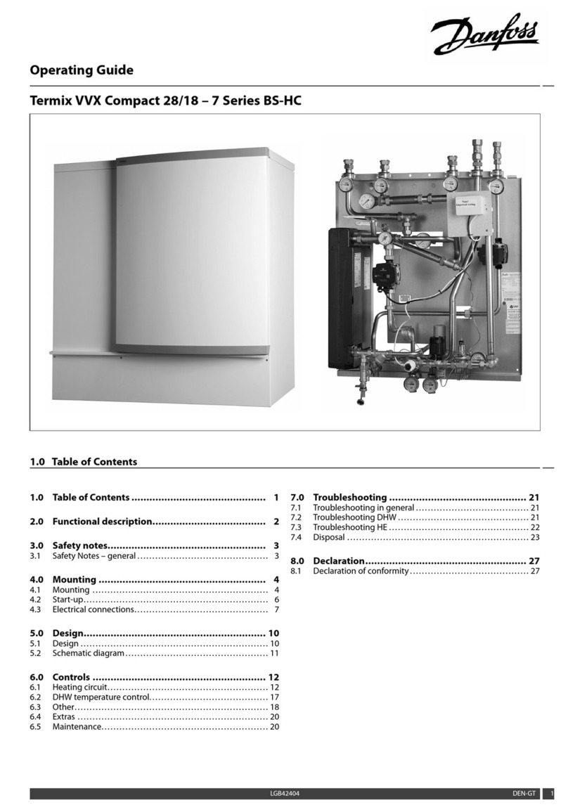
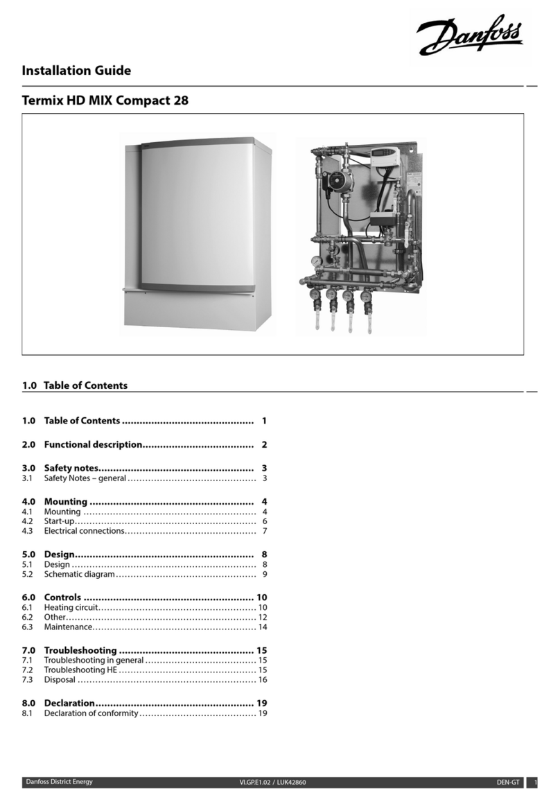
Danfoss InLine User manual

MAKING MODERN LIVING POSSIBLE
Product Description . . . . . . . . . . . . . . . . . . 2
Technical information / specifications . . . . . . . . . 3
Design . . . . . . . . . . . . . . . . . . . . . . . . 4
Dimensions . . . . . . . . . . . . . . . . . . . . . . 5
Installation . . . . . . . . . . . . . . . . . . . . . . 5
Adjustment . . . . . . . . . . . . . . . . . . . . . . 6
Applications . . . . . . . . . . . . . . . . . . . . . 7
Panel variants - left . . . . . . . . . . . . . . . . . . 8
Panel variants - right . . . . . . . . . . . . . . . . . 9
Panel configuration I . . . . . . . . . . . . . . . . .10
Panel configuration II . . . . . . . . . . . . . . . . .11
Heat output I . . . . . . . . . . . . . . . . . . . . .12
Heat output II . . . . . . . . . . . . . . . . . . . . .13
Heat output III . . . . . . . . . . . . . . . . . . . .14
Convec Comfort Panels
InLine product programme
Table of corrections - noise level . . . . . . . . . . . .15
Calculation of pressure loss . . . . . . . . . . . . . .16
Controls . . . . . . . . . . . . . . . . . . . . . . .17
Systems with CHR room thermostat . . . . . . . . . .18
Systems with BMS control . . . . . . . . . . . . . . .19
Information - CHR room thermostat . . . . . . . . . .20
Adjustment of the CHR room thermostat . . . . . . . .21
Information - CHM motor control . . . . . . . . . . .22
Information - TDM power supply . . . . . . . . . . . .23
Power consumption . . . . . . . . . . . . . . . . . .24
Ordering InLine Comfort Panels . . . . . . . . . . . .25
Accessories . . . . . . . . . . . . . . . . . . . . . .26
Notes . . . . . . . . . . . . . . . . . . . . . . . . .27
Placing orders . . . . . . . . . . . . . . . . . . . .28

Convec InLine Panel
InLine is a compact comfort panel that can be used for both
heating and cooling applications in buildings. This product
sheet only covers InLine in heating applications. Please con-
tact Danfoss for advice on InLine in cooling applications.
Applications
Aesthetics and comfort are the keywords for InLine comfort
panels. The discreet panels enable you to create a room
with harmony and balance regardless of the building style
and purpose. InLine panels can be used both as a primary
source of heating or be used in combination with other
heat emitters, e.g. floor heating.
Technical information
InLine panels are built around two finned pipes, which
conduct heated water around the panel. A fan creates an
airstream along two of the finned pipes and transfers heat
to the air in the room.
Unlike tradional flow control, the InLine panel’s power is
controlled by adjusting the fan speed.
InLine can be used in district heating, oil/gas boilers,
heating pumps or similar systems.
Flexible installation
InLine panels are primarily developed for installing in a 90°
corner between two surfaces, e.g. wall/wall, wall/ceiling,
column/wall or similar. Other possibilities could be placing
the panel above or below cable trays or two panels “back to
back” thus forming a half circle.
The Inline panel can also, based on it’s compact dimensions
be integrated into building components.
Consistant performance
As InLine panels operate at the same average temperature
difference along the entire length of the panel, the heating
effect will be uniform over the panel’s entire length.
Product Description
Dimensions
The cross section of a InLine panel is 81 x 81 mm.
Panels can be supplied in lengths of up to 3500 mm (tole-
rance +/-2 mm).
Several panels can be built together creating a up to 15 m
long panel.
Controls
Room temperature is controlled by manually adjusting the
CHR room thermostat to the desired temperature. Alterna-
tively, a 0-10 V signal from e.g. a BMS unit can be send a to
the panel’s motor control.
The thermostat monitors the room temperature constantly
and immediately sends a signal to the panel’s motor con-
trol if the room temperatureis outside the set temperature.
Forced convection
The Convec comfort panels are based on forced convection,
which transmits heat directly into the air in the room.
Traditional heating systems have to first warm up building
sections and their own mass before heat is transferred to
the room air.
Convec comfort panels works in the opposite way: first, the
air in the room is heated and then, the heat is transmitted
to building sections and furniture, etc.
The use of forced convection means that the panels can
increase room temperature very quickly and will often be
able to change the room temperature by several degrees in
quite a short space of time.
Comfort
As the energy supply is quickly and constantly adjusted to
the desired room temperature, the InLine panels will offer
a very high degree of comfort whilst using no more energy
than necessary.
2 VD.YC.D2.02 © Danfoss 01/2006 CONVEC
Technical information / specifications
Weight (without water) 3.8 kg/m
Length per panel unit 1000 - 3500 mm
Storage temperature -10 - 60 °C
Water temperature 8 - 85 °C
Water quality VDI 2035
Max. operating static pressure 10 Bar
Max. test pressure 13 Bar
Air flow, 1500 rpm 85 m3/h per meter panel
Noise level at 1500 rpm *22dB(A)
*Measured a 2.2 m panel, water flow 300 l/h, distance 1.5 m.
Visual optimisation (empty panel casing)
InLine can be supplied as an empty panel casing (without
motor or pipes) for use in projects where for aesthetic rea-
sons a longer panel than necessary to achieve the desired
heating effect is required.
Cold draft
Modern architecture often contains large sections of glass.
Such large window sections can lead to cold draft and
thereby create discomfort in rooms.
Cold draft can be prevented by placing InLine panels along
the window or even integrated into the facade.
Operational conditions
InLine comfort panels can be used in a heating system
with a maximum water temperature of 85°C and a 10 bar
operational static pressure (test pressure = 1.3 x operational
pressure).
Test
Convec comfort panels has been tested by the Danish Insti-
tute of Technology, according to DS/EN 442.
Installation
Installation instructions are given on pages 5 and 6. More
detailed information is supplied in the installation guide
delivered with each panel.
Safety and handling during the building period
During the building period and before installation, it is
important to store and handle InLine panels correctly.
Each panel consists of a variety of precisely manufactured
components, which are sensitive to e.g. knocks or dirt.
It is recommended that final installation is performed in
the building at a time when it will be possible to protect
the panels from damage.
Maintenance
The panel components are developed for long-term use.
Maintenance comprises cleaning front profile and possible
hoovering of panel (as required).
Ordering
See “Ordering” on page 25 and the section “Placing orders”
on the back page.
CONVEC VD.YC.D2.02 © Danfoss 01/2006 3

Design
1. Front profile (aluminium)
2a. Finned pipe, flow (copper)
2b. Finned pipe, return (copper)
3. Sliding bush
4. Pipe holder (aluminium)
5. Hinge clip (steel)
6. Motor
7. Impeller coupling (plastic)
8. Fan (aluminium)
9. Bearing block (aluminium/brass)
10. Installation profile (aluminium)
11. Panel end (aluminium)
4 VD.YC.D2.02 © Danfoss 01/2006 CONVEC
CONVEC VD.YC.D2.02 © Danfoss 01/2006 5
Dimensions
Product dimensions
Convec InLine panels measure 81 mm in width, 81 mm
in height and 108 mm across.
81 mm
81 mm
108 mm
Hinge
The Front profile of the InLine panel is fixed firmly to
the installation profile with hinge clips which allows
the panel to be opened without disassembling the
front profile. The panel can be opened to both sides.
Installation
Connection bracket
A connection bracket is used to connect to the pipe
work system to prevent transmission of any expansions
from the system onto the panel.
The connection bracket can be installed early in the
construction period, which allows the system pipe
work to be completed at an early stage.
Installing the panel
The InLine installation profile can easily be slided over
the connection bracket.
The installation profile can hereafter be fixed firmly to
the support trough pre-drilled holes.

6 VD.YC.D2.02 © Danfoss 01/2006 CONVEC
Front profile
Installation of front profile
The front profile is easily fastened to the installation
profile.
For more information, see the installation instruction
that comes with the panel.
Opening the front profile
The front profile can easily be opened, using a Convec
opening tool (088H4820) which by applying a light
pressure releases the front profile form the installation
profile.
Defining the connection side of the panel
In order to define the left and right connection side of an InLine panel, it is necessary to look at the panel from the
“Fan-side” of the panel.
Left Right

CONVEC VD.YC.D2.02 © Danfoss 01/2006 7
Applications
InLine panels can be used in a traditional two pipe
system or connected in series of lengths of up to 15
m with the potential for intermediary pipe work. The
same panel string can be used for several rooms as the
panel output is controlled by fan speed rather than flow.
InLine panels can also be used in a one pipe system.
However, this will create a different output from each
individual panel.
Contact Danfoss for further information regarding one
pipe systems.
Two pipe system One pipe system

8 VD.YC.D2.02 © Danfoss 01/2006 CONVEC
Panel variants - left
InLine comfort panels are available in six different panel
variants, which differ according to use and panel connec-
tions.
Each panel variant can be supplied in a left or right hand
version. See p. 6 for information on defining left and right
side of the panel.
Stand-alone panels (S & ST) Kv
S-panel: Stand-alone panel unit with connection to
system pipework, incl. return bend with air vent. 1,3
ST-panel: Stand-alone panel unit with connection to
system pipework, incl. return valve with TWA-A thermal
actuator and air vent. 0,9
Connection panel (C) Kv
C-panel with connection to system pipework and nip-
ples for direct panel extension with other panels. 1,4
Extension panel (E) Kv
E-panel for use with direct connection to two panels.,
incl. flexible hoses and nipples. 1,4
Return panels (R & RT) Kv
R-panel: Panel for finishing panel string, incl. flexible
hoses and air vent. 1,4
RT-panel: Panel for finishing panel string, incl. flexible
hoses, air vent and TWA-A thermal actuator. 0,9
Link panel (L) Kv
L-panel for series connection of panels of the same string
that are not connected directly into a panel. Closed at
both ends with connection to tube system. 1,1
Finishing panel (F) Kv
F-panel for ending a series connection panel string before
tubing is connected to the next panel, incl. flexible
hoses and system connection. 1,1

CONVEC VD.YC.D2.02 © Danfoss 01/2006 9
Panel variants - right
The different panel variants can be combined together.
Left or right rotating versions must be requested in orders.
See panel codes for orders on page 25.
PLEASE NOTE! The stated Kv values are used when calcu-
lating the total pressure loss over one or more panels.
See guidance on page 16.
Stand-alone panels (S & ST) Kv
S-panel: Stand-alone panel unit with connection to
system pipework, incl. return bend with air vent. 1,3
ST-panel: Stand-alone panel unit with connection to
system pipework, incl. return valve with TWA-A thermal
actuator and air vent. 0,9
Connection panel (C) Kv
C-panel with connection to system pipework and nip-
ples for direct panel extension with other panels. 1,4
Extension panel (E) Kv
E-panel for use with direct connection to two panels.,
incl. flexible hoses and nipples. 1,4
Return panels (R & RT) Kv
R-panel: Panel for finishing panel string, incl. flexible
hoses and air vent. 1,4
RT-panel: Panel for finishing panel string, incl. flexible
hoses, air vent and TWA-A thermal actuator. 0,9
Link panel (L) Kv
L-panel for series connection of panels of the same string
that are not connected directly into a panel. Closed at
both ends with connection to tube system. 1,1
Finishing panel (F) Kv
F-panel for ending a series connection panel string before
tubing is connected to the next panel, incl. flexible
hoses and system connection. 1,1

10 VD.YC.D2.02 © Danfoss 01/2006 CONVEC
Panel configuration I
Stand-alone solution
As far as possible, panel units of up to 3500 mm should be
constructed in a stand-alone solution.
In principal, this is carried out like a traditional radiator
installation connected to a two tube system.
To ensure maximum output per meter of panel, we
recommend that the panels used are as long as possible.
Two panels each one meter long will have a lower output
than one panel that is 2 metres long. This is because the
non-effective section of the panel is doubled (places for
connection, motor, fittings, etc.).
Stand-alone panel
Max. 3500 mm
Panel extension, 2 panels
Extensions can be used to extend Convec Climate Panels
over the maximum supplied length of 3500 mm.
This is achieved by connecting panels directly together.
The recommended maximum length of panel extension
is 15 m. However, pressure loss in panel extensions must
be checked at all times.
Connection panel Return panel
Max. 3500 mm Max. 3500 mm
Max. 7000 mm
Panel extension, 3 or more panels
Connection panel x number of panel extensions Return panel
Max. 3500 mm Max. 3500 mmMax. 3500 mm
Max. 15000 mm

CONVEC VD.YC.D2.02 © Danfoss 01/2006 11
Panel configuration II
Series connection of panels
In addition to extending panels by direct connection of
Convec panels, it is also possible to connect panels of the
same string by using intermediary tubing in series.
Series connection allows you to successfully run one string
through several rooms.
Series connection
Max. 3500 mm Max. 3500 mm
Series connection using finishing panels
Connection panel Finishing panel
Max. 3500 mm Max. 3500 mm
Max. 7000 mm
Can be connected to a:
- new series connection panel
- new panel extension
- stand-alone panel

12 VD.YC.D2.02 © Danfoss 01/2006 CONVEC
Heat output I
Temperature set: 50/45/20 °C (Fan speed: 1500 RPM)
Panel length Heat output Flow
1.00 - 1.19 m 80 W 14 l/h
1.20 - 1.39 m 137 W 24 l/h
1.40 - 1.59 m 196 W 34 l/h
1.60 - 1.79 m 254 W 44 l/h
1.80 - 1.99 m 313 W 54 l/h
2.00 - 2.19 m 370 W 65 l/h
2.20 - 2.39 m 427 W 75 l/h
2.40 - 2.59 m 487 W 85 l/h
2.60 - 2.79 m 552 W 96 l/h
2.80 - 2.99 m 617 W 108 l/h
3.00 - 3.19 m 683 W 119 l/h
3.20 - 3.39 m 749 W 131 l/h
3.40 - 3.50 m 815 W 142 l/h
Temperature set: 60/50/20 °C (Fan speed: 1500 RPM)
Panel length Heat output Flow
1.00 - 1.19 m 83 W 7 l/h
1.20 - 1.39 m 153 W 13 l/h
1.40 - 1.59 m 226 W 20 l/h
1.60 - 1.79 m 301 W 26 l/h
1.80 - 1.99 m 377 W 33 l/h
2.00 - 2.19 m 453 W 40 l/h
2.20 - 2.39 m 530 W 46 l/h
2.40 - 2.59 m 605 W 53 l/h
2.60 - 2.79 m 681 W 60 l/h
2.80 - 2.99 m 755 W 66 l/h
3.00 - 3.19 m 829 W 73 l/h
3.20 - 3.39 m 902 W 79 l/h
3.40 - 3.50 m 983 W 86 l/h

CONVEC VD.YC.D2.02 © Danfoss 01/2006 13
Heat Output II
Temperature set: 70/40/20 °C (Fan speed: 1500 RPM)
Panel length Heat output Flow
1.00 - 1.19 m 29 W 1 l/h
1.20 - 1.39 m 74 W 2 l/h
1.40 - 1.59 m 131 W 4 l/h
1.60 - 1.79 m 195 W 6 l/h
1.80 - 1.99 m 263 W 8 l/h
2.00 - 2.19 m 333 W 10 l/h
2.20 - 2.39 m 407 W 12 l/h
2.40 - 2.59 m 481 W 14 l/h
2.60 - 2.79 m 556 W 16 l/h
2.80 - 2.99 m 633 W 19 l/h
3.00 - 3.19 m 709 W 21 l/h
3.20 - 3.39 m 787 W 23 l/h
3.40 - 3.50 m 864 W 25 l/h
Temperature set: 75/65/20 °C (Fan speed: 1500 RPM)
Panel length Heat output Flow
1,00 - 1,19 m 140 W 12 l/h
1.20 - 1.39 m 243 W 21 l/h
1.40 - 1.59 m 349 W 31 l/h
1.60 - 1.79 m 457 W 40 l/h
1.80 - 1.99 m 564 W 50 l/h
2.00 - 2.19 m 670 W 59 l/h
2.20 - 2.39 m 775 W 68 l/h
2.40 - 2.59 m 878 W 78 l/h
2.60 - 2.79 m 990 W 87 l/h
2.80 - 2.99 m 1,108 W 98 l/h
3.00 - 3.19 m 1,227 W 108 l/h
3.20 - 3.39 m 1,347 W 119 l/h
3.40 - 3.50 m 1,467 W 129 l/h

14 VD.YC.D2.02 © Danfoss 01/2006 CONVEC
Heat output III
Temperature set: 70/50/20 °C (Fan speed: 1500 RPM)
Panel length Heat output Flow
1.00 - 1.19 m 64 W 3 l/h
1.20 - 1.39 m 134 W 6 l/h
1.40 - 1.59 m 212 W 9 l/h
1.60 - 1.79 m 295 W 13 l/h
1.80 - 1.99 m 380 W 17 l/h
2.00 - 2.19 m 467 W 21 l/h
2.20 - 2.39 m 555 W 24 l/h
2.40 - 2.59 m 643 W 28 l/h
2.60 - 2.79 m 732 W 32 l/h
2.80 - 2.99 m 821 W 36 l/h
3.00 - 3.19 m 910 W 40 l/h
3.20 - 3.39 m 1,000 W 44 l/h
3.40 - 3.50 m 1.089 W 48 l/h
Temperature set: 65/45/20 °C (Fan speed: 1500 RPM)
Panel length Heat output Flow
1.00 - 1.19 m 49 W 2 l/h
1.20 - 1.39 m 108 W 5 l/h
1.40 - 1.59 m 174 W 8 l/h
1.60 - 1.79 m 245 W 11 l/h
1.80 - 1.99 m 319 W 14 l/h
2.00 - 2.19 m 394 W 17 l/h
2.20 - 2.39 m 470 W 21 l/h
2.40 - 2.59 m 548 W 24 l/h
2.60 - 2.79 m 625 W 27 l/h
2.80 - 2.99 m 703 W 31 l/h
3.00 - 3.19 m 781 W 34 l/h
3.20 - 3.39 m 859 W 38 l/h
3.40 - 3.50 m 938 W 41 l/h

500 1000 1500 2000 2500
1,6
1,4
1,2
1,0
0,8
0,6
0,4
0,2
0
47
40
30
22
15
CONVEC VD.YC.D2.02 © Danfoss 01/2006 15
Table of corrections
If it is not possible to install the length of panel required to
achieve sufficient heat, the panel’s effect can be increased
by increasing the fan speed above the nominal 1500 rpm.
As shown in the diagram, the heat effect increases propor-
tional to the speed of the fan.
Table are based upon actual measurements of the InLine
comfort panel’s heat effect.
However, the motor power consumption and the noise level
will rise and it must therefore be ensured that the maximum
power consumption is not exceeded (see diagram page
24), and hence the power supply is not overloaded.
Example:
An InLine panel of 3.0 metres provides, at a flow of 21 l/h, fan speed at 1500 rpm and a temperature set of 70/40/20°
an effect of 709 W.
To increase the effect to 900 W will entail a correction factor of 900/709 = 1.26. The diagram shows that the fan
speed has to be 1950 rpm, creating a noise level of approximately 32 dB(A).
Fan speed, rpm.
Correction factor
Noise level, db(A)
Measurements are performed in accordance with the stand-
ard EN 442.

16 VD.YC.D2.02 © Danfoss 01/2006 CONVEC
Calculating pressure loss
This example is only valid for panels with a nominal fan
speed (1500 rpm).
Kv values for each panel variant are calculated based on a
3.5 m long panel.
Example: Stand-alone panel
Panel variant ST
50 ˚C
60 ˚C
Conditions: Temperature set:
Panel length:
Heat effect (see table, page 12):
Flow (see table, page 12):
Kv values (see Panel variants pages 8-9):
60/50/20 ˚C
3450 mm
983 W
86 l/h
0,9
Pressure loss Δp is calculated using the formula Δp = (q/Kv)2 where q = flow in m3/h.
Pressure loss in this example is therefore: Δp = (0.086/0.9)2 = 0.01 bar
Example: Panels in series
Panel variant C
3500 mm
Panel variant E
2500 mm
Panel variant RT
3500 mm
50 ˚C
60 ˚C
Effect: 983 W
Flow: 86 l/h
Kv value: 1.4
605 W
53 l/h
1.4
983 W
86 l/h
0.9
Information on effect and flow can be found in the table, page 12. Kv values for each panel variant can be found on pages 8-9.
Total effect: ΣP = P1 + P2 + P3983 + 605 + 983 = 2571 W
Total flow: Σq = q1 + q2 + q386 + 53 + 86 = 225 l/h
Total Kv value: = 0.67
Pressure loss Δp is calculated using the formula Δp = (q/Kv)2 where q = flow in m3/h.
Pressure loss in this example is therefore: Δp = (0.225/0.67)2 = 0.1 bar
Kv=
1
√1+1+1
Kv1
2Kv2
2Kv3
2
ΣKv=
1
√1+1+1
1.421.420.92

Control using CHR room thermostat
Control with 0-10 V BMS signal
Control
InLine comfort panels can either be controlled by a CHR room
thermostat or via an external 0-10 V BMS signal.
When using a CHR room thermostat, the panel and thermostat
are connected with a 4-lead cable. If more panels are added to
the same thermostat, they are connected with a 2-lead cable.
When a 0-10 V CTS signal is used to control the panels, “0” is
connected directly into the panel.
PLEASE NOTE! “0” will be shared jointly when using several
power supplies.
CONVEC VD.YC.D2.02 © Danfoss 01/2006 17
0-10 V BMS signal
TDM power supply
CHR room thermostat
TDM power supply

Room #n
CHM # 01
CHR # n
CHR # 01
Room #01
CHM # x
CHM #y
0-10V
H/C
0
24V
0
24V
0-10V
H/C
0
24V
0
24V
24V
0
1 2 3 4 5 6
Power supply
(24-28 Vdc)
24 Vdc
max. 1.1A
CHR
24 Vdc
0 Vdc
24 Vdc
0 Vdc
Heating/Cooling
RPM (0-10 V)
H. valve +
H. valve -
C. valve +
C. valve -
1
2
3
4
5
6
7
8
9
10
24 Vdc
0 Vdc
24 Vdc
0 Vdc
H/C
RPM
HV +
HV -
CV +
CV -
24 Vdc
max. 1.1A
18 VD.YC.D2.02 © Danfoss 01/2006 CONVEC
System with CHR room thermostat
The heating system shown is a 2-pipe system
with flow and return pipes.
CHR room thermostat sends a 0-10 V control
signal to the panel.
A CHR can control up to 10 Convec panels in
the same room.
A Convec panel can be supplied with a valve
to control flow through the panel.
PLEASE NOTE! CHR room thermostats and
CHM motor control have a common “0”.
Electric circuit
CHR room thermostat
CHM motor control

2800
1500
400
1,3 5,0 9,3
System with BMS control
BMS signal, volt
Recommended motor speed
(adjustable 1.000-2.800 rpm)
Max. motor
speed
Control in the BMS system
InLine comfort panels reacts very quickly. The pan-
els will therefore function at its optimum in systems
that include room thermostats with a small time
constant.
The heat output from the panel depends on the
motor rpm and is approximately linear. The precise
relationship between rpm and output is shown on
the graph on page 15.
The relation between the 0-10 V signal to the CHM
motor control and the actual rpm is linear, as shown
in the graph.
As the panels reacts very quickly, a P-band as small
as 0.5K can be used.
Fan speed, rpm
A Convec panel can be controlled directly
from a BMS system by a 0-10 V signal.
Control of min. and max. fan speed is
performed by the BMS system.
However, the CHM motor control will
continue to perform the panel control,
e.g. stopping the motor if blocked or the
control of any decentralized valves.
PLEASE NOTE!
Water supply valves are connected to
cooling outputs 9 and 10.
Boiler Cooler
Heating relay
Cooling
relay
Room#n
Room #01
CONVEC VD.YC.D2.02 © Danfoss 01/2006 19

20
10
30
85 842
78
3
86
|
�
Information - CHR room thermostat
The CHR is the recommended electronic room thermostat
for InLine comfort panels.
The CHR is a PI-regulator with a small P-band, suitable
for fast reacting systems. It measures and determines the
room temperature by controlling the rpm of the fan mo-
tor and hence the panel’s heat effect.
The CHR is equipped with a boost function that tempo-
rarily increases the fan speed and thus ensures quick
heating.
The heat effect to a room will turn off, when switching
off the thermostat (“”). The installation will remain
protected against frost.
Technical information - CHR room thermostat
Voltage supply 24 Vdc (±4V)
Power consumption 6 mA
Temperature adjustment 5 - 30 °C
P-band 0.5 °C
Adjustment of the fan motor’s max. rpm 1,000 - 2,800 rpm
Fan motor rpm in boost function 2,800 rpm
Protection class IP20
External temperature 0 - 50 °C
Transportation temperature -20 -60 °C
Pollution level Level 2
Ball test temperature 75 °C
Software classification Class A
Dimensions (l x h x d) 85 x 86 x 42 mm
Weight 0.143 kg
Approval 73/23/EEC, 89/336/EEC, EN60730-1, EN60730-2-9, EN61000-6-3,
EN61000-6-1
20 VD.YC.D2.02 © Danfoss 01/2006 CONVEC
Table of contents
Other Danfoss Heater manuals

Danfoss
Danfoss Link HC User manual

Danfoss
Danfoss Termix HD MIX Compact 28 User manual

Danfoss
Danfoss Termix VVX Compact 28/18 - 7 BS-HC Series User manual

Danfoss
Danfoss VM2 User manual

Danfoss
Danfoss AME 335 User manual

Danfoss
Danfoss Akva Lux II VXe User manual

Danfoss
Danfoss Akva Vita TDP-F User manual

Danfoss
Danfoss RA 2000 User manual
Popular Heater manuals by other brands

GSI Group
GSI Group Chi-Town Installation & operation

Sunbeam
Sunbeam SFH107 Instruction leaflet

EUROM
EUROM EK5001 operating instructions

Thermon
Thermon HELLFIRE 400 Installation, operation & maintenance instructions

SEELEY INTERNATIONAL
SEELEY INTERNATIONAL Braemar Invertair SACV10D1S installation manual

SRP
SRP S Series Installation, operation and service instructions